Advertisement
Table of Contents
Advertisement
Table of Contents

Related Manuals for HYOSUNG GT 250 R


Summary of Contents for HYOSUNG GT 250 R
- Page 1 GT 125 R GT 250 R Euro 2, karburatormodel ServiceManual Se også FI Service Manual for indsprøjtnings- Holtvej 8-10, Høruphav delene og GT 6470 Sydals 250 Naked for Telefon: +45 73 15 11 00 Fax: +45 73 15 11 01 øvrige service...
- Page 2 HYOSUNG vehicles. Without such knowledge and skills, you should not attempt servicing by relying on this manual only. Instead, please contact your nearby authorized HYOSUNG motorcycle dealer. HYOSUNG MOTORS & MACHINERY INC. � COPYRIGHT HYOSUNG MOTORS & MACHINERY INC. 2006.
- Page 3 & & NOTE Difference between photographs and actual motorcycles depends on the markets.
-
Page 4: How To Use This Manual
HOW TO USE THIS MANUAL TO LOCATE WHAT YOU ARE LOOKING FOR: 1. The text of this manual is divided into sections. 2. As the title of these sections are listed on the previous page as GROUP INDEX, select the section where you are look- ing for. -
Page 6: General Information
GENERAL INFORMATION CONTENTS EXTERIOR ILLUSTRATION ……………………………………………… 6 (1-6) SPECIFICATIONS ………………………………………………………… 7 (1-8) -
Page 7: Exterior Illustration
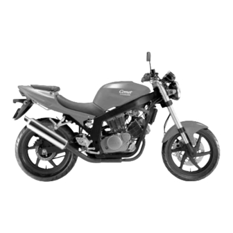
1- 6 GENERAL INFORMATION EXTERIOR ILLUSTRATION [ & Turn signal lamp (Rear) Tail / Brake lamp Rear License plate lamp reflector Turn signal lamp (Front) Head lamp Passenger footrests (WHEEL BASE) (LENGTH) -
Page 8: Specifications
GENERAL INFORMATION 1-8 SPECIFICATIONS DIMENSIONS AND DRY MASS I T E M Overall length 2,060 mm (81.1 in) ← 655 mm (25.8 in) Overall width ← 1,125 mm (44.3 in) ← Overall height Wheelbase 1,435 mm (56.5 in) ← Ground clearance 130 mm (5.1 in) ←... - Page 9 1-9 GENERAL INFORMATION CHASSIS I T E M Front suspension Telescopic type ← Rear suspension Swingarm type ← Steering angle 27°(right & left) ← Caster 25.5° ← Trail 90 mm (3.54 in) ← Front brake Double disc brake Disc brake Rear brake Disc brake ←...
-
Page 10: Periodic Maintenance
PERIODIC MAINTENANCE CONTENTS MAINTENANCE PROCEDURES CARBURETOR ………………………………………………………… 10 (2-7) CLUTCH ………………………………………………………………… 11 (2-8-1) -
Page 11: Maintenance Procedures
2-7 PERIODIC MAINTENANCE MAINTENANCE PROCEDURES CARBURETOR Inspect Interval Inspect Initial 1,000 km and Every 4,000 km. ◉ ◉ IDLE SPEED NOTE Make this inspection when the engine is hot. ● Connect an engine tachometer to the high tension cord. Start up the engine and set its speed at anywhere 1,400 and 1,500 rpm by turning throttle stop screw �. - Page 12 2-8-1 PERIODIC MAINTENANCE CLUTCH ◉ ◉ FOOTREST POSITION ADJUSTMENT � & have 3 type of the footrest position, right and left. � To change the position, remove the 8mm wrench bolts ①, ② and install the bolts to the desired position by using the hexagon wrench 6mm.
- Page 13 PERIODIC MAINTENANCE 2-8-2 ◉ ◉ GEARSHIFT LINK ROD (FOR & ’S OPTIONAL PARTS) When the footrests in position �, exchange the gearshift ③ ③ link rod for appropriate riding position. ● Position � or � : Install the gearshift link rod ③ ●...
-
Page 14: Electrical System
ELECTRICAL SYSTEM CONTENTS LAMP………………………………………………………………………… 14 (5-16-1) - Page 15 ELECTRICAL SYSTEM 5-16-1 LAMP ◉ ◉ HEAD LAMP � � REPLACEMENT OF HEAD LAMP BULB ● Remove the under cowling. (Refer to page 6-1-2 ~ 3) ● Remove the body cowling. (Refer to page 6-1-4 ~ 5) ● Remove the head lamp coupler ①, ②. ②...
- Page 16 5-16-2 ELECTRICAL SYSTEM ● Remove the socket spring ①. ① ● Remove the bulb ② and replace the new bulb. ② ● Remove the head lamp “HI” bulb with the same manner of the head lamp “LOW” bulb removal. ● Reinstall the head lamp bulb in the reverse order of head lamp bulb removal.
- Page 17 ELECTRICAL SYSTEM 5-17-1 ◉ ◉ COMBINATION METER Remove the combination meter. Disassemble the combination meter as shown in the illustration. � � INSPECTION Using the pocket tester, check the continuity between lead wires in the following illustration. If the continuity measured incorrect, replace the respective part.
- Page 18 5-17-2 ELECTRICAL SYSTEM...
-
Page 20: Chassis
CHASSIS CONTENTS EXTERIOR PARTS ………………………………………………………… 20 (6-1-1) HANDLEBARS …………………………………………………………… 25 (6-12-1) STEERING ………………………………………………………………… 29 (6-27) -
Page 21: Exterior Parts
6-1-1 CHASSIS EXTERIOR PARTS ◉ ◉ REAR CARRIER � � REMOVAL ● Open the rear seat with the ignition key. ● Remove the rear carrier mounting bolts ① and ② separate the rear carrier ②. ① ① � � INSTALLATION Reassemble the rear carrier in the reverse order of removal. - Page 22 CHASSIS 6-1-2 ◉ ◉ UNDER COWLING � � � � ① Under cowling RH ③ Under center cowling ② Under cowling LH ④ Under center cowling grill...
- Page 23 6-1-3 CHASSIS � � REMOVAL ● Remove the under cowling screws at the rightside. ● Remove the under cowling screws at the leftside.
- Page 24 CHASSIS 6-1-4 ◉ ◉ BODY COWLING � � � � � � � � � � ① Windscreen ⑤ Body side cowling inner RH ⑨ Air duct cowling LH ② Meter panel ⑥ Body side cowling lower RH ⑩ Body center lower cowling ③...
- Page 25 6-1-5 CHASSIS � � REMOVAL ● Remove the body cowling screw at the rightside. ● Remove the body cowling screw at the leftside. ● Remove the two cowling brace bolts. ● Remove the speedometer lead wire and head lamp lead wire. �...
- Page 26 CHASSIS 6-12-1 HANDLEBARS � � � � � � ① Handlebar composition RH ③ Rear view mirror assembly RH ⑤ Handlebar switch assembly RH ② Handlebar composition LH ④ Rear view mirror assembly LH ⑥ Handlebar switch assembly LH ■ ■ HANDLEBAR RIGHT SIDE PARTS REMOVAL ●...
- Page 27 6-12-2 CHASSIS ■ ■ HANDLEBAR LEFT SIDE PARTS REMOVAL ● Remove the left handlebar switches. ● Remove the handlebar balancer ① and grip ②. ● Remove the clutch lever holder. ① ② ● Loosen the handlebar clamp bolts, right and left. ●...
- Page 28 CHASSIS 6-13-1 ● Remove the handlebar holder bolt, right and left. ● Draw out the handlebars to upward. ■ ■ REMOUNTING Remount the handlebar in the reverse order of removal. Pay attention to the following point : ● Install the handlebars temporary. ●...
- Page 29 6-13-2 CHASSIS ● When remounting the clutch lever holder, align the holder’s mating surface � with punch mark � on the Upper � handlebar. Clutch lever holder Handlebar � � ● When remounting the front brake master cylinder Upper onto the handlebar, align the master cylinder holder’s �...
-
Page 30: Removal And Disassembly
CHASSIS 6-27 STEERING ◉ ◉ REMOVAL AND DISASSEMBLY ● Remove the under cowling and body cowling. (Refer to page 6-1-2 ~ 5) ● Take off the front wheel. ☞ Refer to the service manual 『 (99000-94710) page 6-2 ● Remove the four bolts and front fender. ●... - Page 31 6-28 CHASSIS ● Remove the handlebar clamp bolts. ● Remove the steering stem head nut ① and take off the steering stem upper bracket ②. ① ② ● Remove the steering stem nut ③ and draw out the steering stem. ③...
- Page 32 CHASSIS 6-29-1 ◉ ◉ INSPECTION Inspect and check the removed parts for the following abnormalities. ∙Handlebar distortion. ∙Handlebar clamp wear. ∙Abnormality operation of bearing. ∙Worn or damaged races. ∙Distortion of steering stem. ◉ ◉ REASSEMBLY Reassemble and remount the steering stem in the reverse order of disassembly and removal, and also ②...
- Page 33 6-29-2 CHASSIS ● Tighten the handlebar clamp bolts, right and left. Handlebar clamp bolts : 22 ~ 35 N∙ ∙ m (2.2 ~ 3.5 kg∙ ∙ m)
-
Page 34: Servicing Information
SERVICING INFORMATION CONTENTS SERVICE DATA …………………………………………………………… 34 (7-20) WIRING DIAGRAM ………………………………………………………… 35 (7-31) -
Page 35: Service Data
7-20 SERVICING INFORMATION SERVICE DATA WATTAGE Unit : W ITEM SPECIFICATION H1 : 55W Head lamp H3 : 55W Position lamp License plate lamp Brake/Tail lamp 21/5W Turn signal lamp Front : 10W×2 / Rear : 10W×2 llumination lamp 1.7W×2 Neutral indicator lamp Turn signal indicator lamp (Right &... - Page 36 SERVICING INFORMATION 7-31 WIRING DIAGRAM...
- Page 37 Prepared by HYOSUNG MOTORS & MACHINERY INC. 1st Ed. JUL. 2006. Manual No. 99000HR8310 Printed in Korea...
Need help?
Do you have a question about the GT 250 R and is the answer not in the manual?
Questions and answers
DO YOU HAVE A CAM TIMING DIAGRAM FOR A 2010 GTR 250
@PAUL SHARPE