Advertisement
Quick Links
69
Glue the scale exhaust to the cowling,and clue the
exhaust tube to the exhaust as illustration.
70
Fix the exhaust tube via Plastic plate and screws.
Screw
Nut
2mm
Screw (2x10mm)
4
Nut (2mm )
4
TP Screw (2.3x8mm)
4
Plastic plate
4
71
Adjustment of the aileron and flap,be sure they can work
perfectly.
AILERON
40mm
40mm
AILERON
AILERON
AILERON
AILERON
72
Adjustment of the rudder, be sure it can work perfectly.
Side View
RUDDER
Top view
50mm
50mm
73
Adjustment of the elevator,be sure it can work perfectly.
ELEVATOR
Top view
40mm
40mm
Position for
right diagram.
74
Centre of the Gravity.
130mm
130mm
14
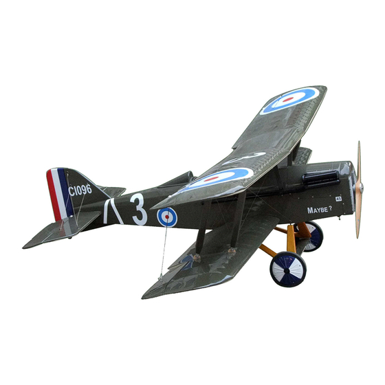
SE 5A
Specification:
Length
:1397 mm(55")
Wing Span
:1803 mm(71")
Wing Area
:113sq.dm
12.2sq.ft
Wing Loading :56.6g/sq.dm
18.6oz/sq.ft
Flying Weight :6.4kg(14.1lbs)
Radio
:6ch & 5servos
Engine:
:26cc-36cc
SAFETY PRECAUTIONS
INSTRUCTION MANUAL
This R/C airplane is not a toy!
(The people under 18 years old is forbidden from flying this model)
First-time builders should seek advice from people having building
experience.If misused or abused,it can cause serious bodily injury
and damage to property.
Fly only in open areas and preferably at a dedicated R/C flying site.
We suggest having a qualified instructor carefully inspect your
airplane before its first flight.Please carefully read and follow all
instructions included with this airplane,your radio control system
and any other components purchased separately.
Advertisement

Related Manuals for Royal Aircraft se 5a

Summary of Contents for Royal Aircraft se 5a
-
Page 1: Instruction Manual
Glue the scale exhaust to the cowling,and clue the Adjustment of the rudder, be sure it can work perfectly. exhaust tube to the exhaust as illustration. SE 5A Side View RUDDER Top view 50mm 50mm Adjustment of the elevator,be sure it can work perfectly. - Page 2 Assemble the scale wheels to the model throught the rod shaft. Glue the PVC parts to appropriate position on the cockpit. TP Screw (2.3x8mm) LockNut(5mm) Ply (3mm) Ply (3mm) (with 8 servos), TP Screw (2.3x8mm) 6 channel radio for aiplane is highly recommended for this model. Wheel (150mm) Fix the undercarriage to the fuselage with gear plates and Assemble the cockpit to the fuselage via screws as...
-
Page 3: Accessory List For The Coming Installation Steps
Apply instant type AB glue to appropriate position in the Assembly of the fuel tank. Accessory list for the coming installation steps. Accessory list for the coming installation steps. trailing edge and assemble the ailerons to them. Collar (5mm) Rod (2.5x300mm) LockNut (5mm) TP Screw (2.3x12mm) Main landing gear... - Page 4 Install the engine mount tubes to the fuselage,lock them Apply instant type AB glue to the control horn and the slots in The sketch map when the engine install completion. Insert the main wing joiner to one side of the lower wing. from inside of the fuselage.
- Page 5 Link the wires of the elevator to the servo,assemble the Apply instant type AB glue to appropriate position in the The front view once the engine install completion. Accessory list for the coming installation steps. elevator servo to appropriate position in the fuselage. trailing edge and assemble the ailerons to them.
- Page 6 Fix the wing struts of the centre wing to the centre Fix the wing struts to the appropriate position between the The sketch map of the pushrods for the rudder in the Epoxy the rudder to the vertical fin. wing & fuselage as illustration. upper wings and lower wings.
- Page 7 Assemble the linkage to the control horn in the lower wing's Fix the steel wires to the blind nud which applied in the The sketch map of the steel wires work for stabilizer. Assemble the tail wheel to the rudder as illustration. fuselage and wings with screws.
- Page 8 Link the upper wing aileron and lower wing aileron via the Apply instant type AB glue to appropriate position of the elevator and Assemble the linkage rods for elevator lock the linkage to the control horn with screw and nut. pivot &...
Need help?
Do you have a question about the se 5a and is the answer not in the manual?
Questions and answers