Sign In
Upload
Download
Table of Contents
Contents
Add to my manuals
Delete from my manuals
Share
URL of this page:
HTML Link:
Bookmark this page
Add
Manual will be automatically added to "My Manuals"
Print this page
×
Bookmark added
×
Added to my manuals
Manuals
Brands
Danfoss Manuals
Amplifier
OSQA
Service manual
Danfoss OSQA Service Manual
Flow amplifier
Hide thumbs
1
2
Table Of Contents
3
4
5
6
7
8
9
10
11
12
13
14
15
16
17
18
19
20
21
22
23
24
25
26
27
28
29
30
31
32
33
34
35
36
37
38
39
40
41
42
43
44
page
of
44
Go
/
44
Contents
Table of Contents
Bookmarks
Table of Contents
Table of Contents
Safety Precautions
Symbols Used in this Literature
OSQ Versions
Technical Specifications
Exploded View
Parts List
OSQA and OSQB Parts List
OSQ Spare Parts List
Tools
Disassembly
Dismantling Counter Pressure Valve
Removing Pressure Relief Valve
Removing End Cover at PP-Connection
Removing End Cover at LS-Connection
Unscrew Orifices, Throttle Check Valve
Housing and End Cover with Accessories
Spools with Accessories
Dismantling Directional Spool
Priority Valve Spool Number of Orifices
Dismantling Priority Valve Spool
Dismantling Amplifier Spool
Shock and Suction Valves
Cleaning
Inspection and Replacement
Lubrication
Assembly
Assembling Shock, Suction, and Check Valve
Assembling Amplifier Spool
Assembling Priority Valve Spool
Assembling Directional Spool
Installing Orifice and Throttle Check Valve
Installing Shock Valves
Assembling Pressure Relief Valve
Installing OSQB Back Pressure Valve
Installing Spools
Installing PP End Cover
Installing LS End Cover
Plastic Plugs
Testing
Set-Up for Testing
Steering Test Using Steering Unit Type OSPBX LS
Pilot Relief Valve
Neutral Positioning
Manual Steering Test
Advertisement
Quick Links
1
Table of Contents
2
Osq Versions
3
Osqa and Osqb Parts List
4
Exploded View
5
Parts List
6
Dismantling Counter Pressure Valve
7
Set-Up for Testing
8
Manual Steering Test
Download this manual
Service Manual
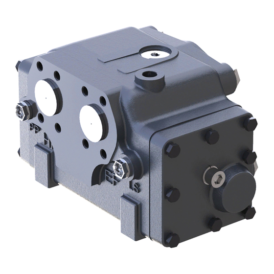
Flow amplifier
OSQA/OSQB
powersolutions.danfoss.com
Table of
Contents
Previous
Page
Next
Page
1
2
3
4
5
Advertisement
Table of Contents
Need help?
Do you have a question about the OSQA and is the answer not in the manual?
Ask a question
Questions and answers
Related Manuals for Danfoss OSQA
Amplifier Danfoss OSQB Service Manual
Flow amplifier (44 pages)
Amplifier Danfoss EEA-PAM-591-A-10 Installation Manual
Servo amplifier (20 pages)
This manual is also suitable for:
Osqb
Table of Contents
Save PDF
Print
Rename the bookmark
Delete bookmark?
Delete from my manuals?
Login
Sign In
OR
Sign in with Facebook
Sign in with Google
Upload manual
Upload from disk
Upload from URL


Need help?
Do you have a question about the OSQA and is the answer not in the manual?
Questions and answers