
Subscribe to Our Youtube Channel
Related Manuals for Cantek KQ0824 Series

Summary of Contents for Cantek KQ0824 Series
- Page 1 Standalone Digital Video Recorder Premium DVR 4, 8, 16 Channel Models User`s Manual MADE IN KOREA M2923KQCR This document contains preliminary information and is subject to change without notice.
- Page 2 FCC Compliance Statement Notice to Users This equipment has been tested and found to comply with the limits for a Class A digital device. Pursuant to Part 15 of the FCC Rules, these limits are designed to provide reasonable protection against harmful interference when the equipment is operated in a commercial environment.
- Page 3 Cautions This product has free voltages (100V ~ 240V). See installation instructions before connecting to the power supply. This product uses a Lithium battery. To avoid any risk of explosion, do not replace the battery on the main board by anything other than a Lithium battery. ...
- Page 4 12. Servicing Do not attempt to service this equipment yourself. Refer all servicing to qualified service personnel. 13. Damage Requiring Service Unplug this equipment from the wall outlet and refer servicing to qualified service personnel under the following conditions: ①...
- Page 5 The List of Configuration A Type : 4 CH B Type : 4CH DVR Set C, D, E and F Type : 4 / 8 / 16CH Manual / CMS CD Remote Controller Manual Screws HDD Brackets Rack Bracket (Except A and B Type Model) Data Cable Power Cable Adapter...
-
Page 6: Operation Precautions
Operation Precautions Power Off Do not turn DVR off, or plug off the power adapter while DVR is in operation (record/playback). Otherwise, it may cause permanent damage to the equipment. Please click ( ) SETUP>SYSTEM>Shutdown sequentially and then remove the power after DVR is shutdown completely. -
Page 7: Table Of Contents
Table of Contents Server 4.2.2 Admin ..............32 4.2.3 Account ..............35 PRODUCT FEATURES ..........12 4.2.4 System Log ............. 37 Unpacking ..............12 4.2.5 Exit ................38 4.2.6 Shutdown ..............38 Service ..............12 DISPLAY ..............38 System Connection Diagram ........12 4.3.1 OSD ................ - Page 8 One-touch Playback ..........66 6.4.2 Remote Search ............85 Digital Zoom in Playback .......... 66 6.4.3 Local Search .............. 85 Archive ..............67 6.4.4 Event Search .............. 86 Menu Bar ..............68 6.4.5 Playback ..............86 6.4.5.1 Playback Control Button ........86 Color Control and Position ........
- Page 9 7.4.2.2 Viewer ............... 103 7.7.5 Sequencing .............. 126 7.4.2.2.1. Audio ............103 7.7.6 Audio Volume Control..........127 7.4.2.2.2. Video Display ........... 103 7.4.2.3 Record ............... 104 7.4.2.4 Setup ..............104 7.8 SEARCH ..............128 7.4.2.5 Instant Playback ..........105 7.8.1 Overview ..............128 7.4.3 Local Setup - Account ..........
- Page 10 9.8.1 Login Screen ............153 12.6 Connection ............190 9.8.2 Local Setting ............153 12.6.1 Configuration Diagram I ........190 9.8.3 Live ............... 157 12.6.2 Configuration Diagram II ........190 12.6.3 Configuration Diagram III ........191 Search Mode ............160 9.9.1 Date/Time Search ..........
- Page 11 14.8 HSR1110 ............207 14.8.1 Introduction ............207 14.8.2 Features ............. 207 14.8.3 Technical Specification ........208 14.8.4 Unpacking ............208 14.8.5 Service ............... 208 14.8.6 System Dimension Diagram ....... 208 14.8.7 Connector Wiring..........208 14.8.8 Cable ..............209 14.8.9 Display ............... 209 14.9 HSR1440 ............
-
Page 12: Product Features
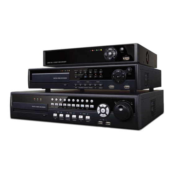
1. Product Features 1.1 Unpacking This equipment is an electronic appliance, so it should be handled with special care. After unpacking, please check if all the following items are included. - DVR Main body A Type : Power Supply Adapter (DC 12V, 5A) and Power Supply Cable B, C(4CH) Type : Power Supply Adapter (DC 12V, 6.67A) and Power Supply Cable C(8,16CH), D, E and F Type... - Page 13 B Type – 4 channel Series HD-SDI DVR...
- Page 14 C Type – 4 / 8 / 16 channel Series HD-SDI DVR...
- Page 15 D Type – 4 / 8 channel Series HD-SDI DVR...
- Page 16 E Type – 4 channel Series HD-SDI DVR...
- Page 17 F Type– 16 channel Series Hybrid DVR...
-
Page 18: Installation
2. Installation 2.1 Hard disk and DVD-RW Installation 2.1.1 SATA Port A Type - Main substrate of this DVR has one SATA port: it is indicated as SATA 1. - Only one SATA device (hard disk) is possible to connect in Serial to the SATA port. ... -
Page 19: Hdd Installation
D, E and F Type SATA 5 Storage SATA 1, 2 Port SATA 3, 4 Port Port DVD-RW DVD-RW 4 / 8 / 16 CH DVR DVD-RW DVD-RW DVD-RW 2.1.2 Internal SATA Storage (C / D / E and F Type) ... -
Page 20: Maximum Hdd Capacity
CAUTION For installation/addition/replacement/Removal of HDD (DVD-RW), make sure that DVR is turned off. Otherwise, it may cause permanent damage to the HDD (DVD-RW). Installation/Addition/Moving/Replacement: User should start ‘HDD initialization’ including formatting. Otherwise, DVR won’t recognize the hard disk and may begin to function abnormally. Please follow the below procedure for ‘HDD initialization’. ①... -
Page 21: Hd-Sdi Input Signal Detection
2.2.3 HD-SDI Input Signal detection A, B, C and D Type These type of DVRs will automatically detect the input signals from 720P 24, 720P 25, 720P 30, 720P 50, 720P 60, 1080I 50, 1080I 60, 1080P 24, 1080P 25, 1080P 30, 1080P 50, 1080P 60 (Auto Detection) when the system starts. ... -
Page 22: Alarm Connections
2.2.8 Alarm Connections Connect Alarm Input (Sensor) to ‘AI 1~AI 4 (or AI 16)’ connectors and connect Sensor Common to ‘G’ connector. Connect Alarm Output (buzzer, siren, etc.) to ‘AO 1~AO 4 (or AI 16)’ connectors and connect Common to ‘G’ connector. ... -
Page 23: Input Device And Screen Icons
3. Input Device and Screen Icons 3.1 Key and LEDs B Type KEYS PTZ KEY Operating mode Setup mode •Up/Down/Left/Righ ▲, ▼, ◄, ► • Control Pan/Tilt rotation of up/down/left/right in PTZ mode t on screen cursor control • Camera select keys : (4/8 channel DVR) 1 ~ 10 •... - Page 24 C,D,E and F Type KEYS PTZ KEY Operating mode Setup mode •Up/Down/Left/Righ ▲, ▼, ◄, ► • Control Pan/Tilt rotation of up/down/left/right in PTZ mode t on screen cursor control • Camera select keys : (4/8/16 channel DVR) 1 ~ 16 •...
-
Page 25: Camera Select Keys For 16 Channel Dvr
3.2 Camera Select Keys for 16 Channel DVR B Type Below shows how to select camera channel for 4 channel Select Camera No. 1~4: press key and use 1~4 Below shows how to select camera channel for 8channel Select Camera No. -
Page 26: Using A Remote Controller
C, D, E and F Type 4 Channel DVR Channel DVR Channel DVR 3.4 Using a Remote Controller Usage of a remote controller is same as the front panel keys. Follow the procedure below when using the remote controller for multi DVRs. ①... -
Page 27: Screen Icon
B, C, D, E and F Type Function Name of Key Name of Key Function Same as front key Display Event Same as front key (indicate System Log) One-touch playback (same function with Same as front key Sequence Search (PLAY/PAUSE) Same as front key Spot Setup... -
Page 28: Setup
4. Setup 4.1 Login / Logout At the default setting of DVR, user has to input the password to enter the set up menu. Please press SETUP key to enter the setup menu and the following screen will appear. ... -
Page 29: System
4.2 SYSTEM 4.2.1 Information Please click ( ) SYSTEM>Information and the following screen will appear. Status Site Description Decide on a name of DVR. Please click ( ) keyboard icon on Site Description frame and the following virtual keyboard will appear. ... - Page 30 Import: Copy the Menu setup stored in USB memory stick into DVR. Please plug in the memory stick and then click ( ) Import. Export: Store the Menu setup of DVR in USB memory stick. Please plug in the memory stick and then click ( ) Export. ...
- Page 31 Overwrite Setting Click ( ) Overwrite Setting button and the following screen will appear. User shall designate the total recording days from 1 day to 30 days and unlimited. User may set for beeping or notifying messages that notify the used percentage of disk. ...
-
Page 32: Admin
4.2.2 Admin Please click ( ) SYSTEM>Admin and the following screen will appear. Date / Time Date This menu will allow user to adjust the settings. Please follow the procedure below for time adjustment. ① Click ( ) items (Y, M, D) to change. A designated item will be highlighted in a box (Y: Year, M: Month and D: Date). ②... - Page 33 Date Format Set date indication format. Please click ( ) Date Format frame to select a format from the list. Time Format Set time indication format. Please click ( ) Time Format frame to select a format from the list. ...
- Page 34 Clicking Up and Down button for checking up the status of HDD and DVD-RW devices. Using E-SATA port will allow users to connect up to maximum 12 HDD +1 DVD-RW. When user installs full storage device and DVD-RW including two e-SATA storage, then following procedures will be listed as below: - 1.
-
Page 35: Account
If “Use on” box is unchecked, Beep, Blink Message will be unchecked automatically. Only when “Use on” is checked, user can set Beep, Blink Message function. Click ( ) Inspection Time frame to set inspection time. Click Check by frame to select inspection interval. ... -
Page 36: New User
Choose ‘OK’ to confirm the setting. New User Please click ( ) New User and the following screen will appear. Click ( ) the keyboard icon on the right-hand side of User Name frame and the virtual keyboard will appear. Click desired characteristics (up to 8 characteristics) on the virtual keyboard. -
Page 37: System Log
This is a screen for password resetting. Input password by clicking the keyboard icon on the right-hand side of the frame. Use key if wish to erase password on keyboard. 4.2.4 System Log Please click ( ) SYSTEM>System Log and the following screen will appear. ... -
Page 38: Exit
System Log removal procedure is as follows: - Execute Clear All Data in SYSTEM>Information>Record and choose ‘OK’ on the popup dialogue box. Please note that all normal recorded video data are deleted from database. - Press Factory Reset Switch on the back panel. Please note that the entire menu setup is also defaulted. 4.2.5 Exit ... -
Page 39: Main Monitor
OSD Margin The OSD Margin menu will allow user to adjust the position of OSD (letters) on the monitor. Use it when some of letters are dropped out and invisible on the monitor. Adjust Horizontal to change margin between both ends of the monitor on horizontal side and OSD. Margin range is between 0 and 50, with a larger number representing greater margin. -
Page 40: Spot Monitor
X9 Seq Use only with 16 channel DVR. Adjust interval for ‘X9 Split Screen sequencing’. Check check box next to the camera that wish to include in sequencing. Any camera with unchecked check box will be excluded from channel sequencing. -
Page 41: Vga
Quad Seq Use only with 8 / 16 channel DVRs. Adjust interval for ‘X4 Split Screen sequencing’. Check check box next to the camera that wish to include in sequencing. Any camera with unchecked check box will be excluded from channel sequencing. -
Page 42: Devices
Once it has changed, it will ask to reboot for the new recognition of video out method The default value is NTSC 4.4 DEVICES Please click ( ) DEVICES and the following screen will appear. 4.4.1 Network ... - Page 43 In DHCP, IP Address, Subnet Mask, Gateway and DNS Server will have input automatically. DNS Server When user set Network Type to DHCP, DNS server will be inputted automatically. When user set Network Type to Static, please click ( ) the keyboard icon on the right-hand side of DNS Server frame and manually input the address.
- Page 44 When user press Get Domain Name button, Domain Name and MAC Address value will automatically display after 10 seconds. Choose ‘OK’ to confirm the setting. 3 Party - Check a checkbox of 3 Party to use dyndns.org or no-ip.com Server. - As for DDNS Server, dyndns.org will be showing as default.
- Page 45 NOTE “Enable Dual Streaming” and click “OK” button, DVR will automatically reboot. (A, B and C type cannot select If users check the the dual streaming function) CAUTION IT IS NOT ABLE TO CHANGE Port Number DURING CMS ACCESS TO DVR. CAUTION PLEASE CHECK THE ROUTER FOR UPNP SUPPORTABILITY BEFORE START USING THE UPNP FEATURE.
-
Page 46: Camera / Ptz
4.4.2 Camera / PTZ Please click ( ) DEVICES>Camera/PTZ and the following screen will appear. Click ( ) the keyboard icon on the right-hand side of each frame on Title column and the virtual keyboard will appear. Then, register titles of cameras. -
Page 47: Audio
4.4.3 Audio Please click ( ) DEVICES>Audio and the following screen will appear. The Audio menu will allow user to choose whether to record Audio. When a check box is marked on No column, corresponding audio and video are recorded. However, if the check box is not marked, audio is not recorded. -
Page 48: Alarm Out
4.4.5 Alarm Out Please click ( ) DEVICES>Alarm Out and the following screen will appear. The Alarm Out menu will allow user to give title and to select the type and duration of Alarm output. Click ( ) the keyboard icon on the right-hand side of each frame on Title column and the virtual keyboard will appear. Then, please register the title of Alarm output. -
Page 49: Setting
4.5.1 Setting Please click ( ) RECORD>Settings and the following screen will appear. There are three kinds of recording mode. - Continuous: record continuously. - Event: record only when Sensor or Motion calls. - Emergency: record when press EMERGENCY key. Continuous ... - Page 50 F Type HD-SDI Input (CH 1~2) 360x 240(288) 720x240(288) 720x480(576) 1280 x 720 1920 x 1080 2 Channel Max. 30 fps per Channel Max. 30 fps per Channel Max. 30 fps per Channel Max. 30 fps per Channel Max. 25 fps per Channel ...
- Page 51 A Type 360x 240(288) 720x240(288) 720x480(576) 1280 x 720 1920 x 1080 4 Channel DVR Max. 30 fps per Channel Max. 30 fps per Channel Max. 30 fps per Channel Max. 15 fps per Channel Max. 7 fps per Channel B Type 360x 240(288) 720x240(288)
- Page 52 CAUTION IF USER CONNECTS DIFFERENT TYPES OF HD-SDI SIGNALS WHILE DVR IS OPERATING. IT MAY CAUSE MALFUNCTIONS OF DVR. Emergency Please click ( ) Emergency and the following screen will appear Emergency. The Emergency menu will allow user to set Emergency videos. ...
-
Page 53: Schedule
F Type HD-SDI Input (CH 1~2) 360x 240(288) 720x240(288) 720x480(576) 1280 x 720 1920 x 1080 2 Channel Max. 30 fps per Channel Max. 30 fps per Channel Max. 30 fps per Channel Max. 30 fps per Channel Max. 25 fps per Channel ... -
Page 54: Pre Alarm
Repeat the procedure for Camera Nos. 2 to 16. If user wants every camera to have the same mode, please click ( ) Copy to All Camera. Below lists symbols of the respective recording modes. Continuous Alarm In Alarm In / Continuous Alarm In / PreAlarm Motion... - Page 55 A Type 360x 240(288) 720x240(288) 720x480(576) 1280 x 720 1920 x 1080 4 Channel DVR Max. 30 fps per Channel Max. 30 fps per Channel Max. 30 fps per Channel Max. 15 fps per Channel Max. 7 fps per Channel B Type 360x 240(288) 720x240(288)
-
Page 56: Motion Detection
CAUTION IF USER CONNECTS DIFFERENT TYPES OF HD-SDI SIGNALS WHILE DVR IS OPERATING. IT MAY CAUSE MALFUNCTIONS OF DVR. 4.5.4 Motion Detection Please click ( ) RECORD>Motion Detection and the following screen will appear. The Motion Detection menu will allow user to set Motion detection alarm. ... -
Page 57: Link
Since holidays may vary every year, we recommend user to update on a regular basis. Choose ‘OK’ to confirm the setting. 4.6 LINK Please click ( ) LINK and the following screen will appear. The LINK menu will allow user to set recording modes of all kinds of alarms (Sensor, Motion Event, Video loss, System Event, etc.), alarm output, e-mail notification and the like. -
Page 58: Motion Event
4.6.2 Motion Event Please click ( ) LINK>Motion Event and the following screen will appear. Select cameras for recording while the motion sensor is in operation and alarm outputs and set up E-mail addresses for notification. Link Notification displays E-mail addresses registered in DEVICES>Network>Notification. ... -
Page 59: System Event
Click No Beep to deactivate alert sounds from video loss. Apply to all channels. Choose ‘OK’ to confirm the setting. 4.6.4 System Event Please click ( ) LINK>System Event and the following screen will appear. Select recording cameras and alarm outputs while Emergency recording using EMERGENCY key and set E-mail addresses for notification. -
Page 60: Operation Instruction
5. OPERATION INSTRUCTION 5.1 Viewing 5.1.1 First Images Power on DVR and the following live video will appear, while viewing and recording at the same time. The screen will display date/time and icons below. Icon Description Continuous recording mode Event recording mode (Alarm In/Motion) In recording PTZ registration/PTZ mode... -
Page 61: View Format
5.1.2 View Format The available view formats when the Main Monitor is in viewing mode include Full Screen, Split Screen, Channel Sequencing Screen and PIP screen. - Full Screen: Please press camera select key (1~16) to view the corresponding camera image in full view format. NOTE Using a mouse: Double click to view the corresponding camera image in full view format and click one more time to back to Split Screen. -
Page 62: System Log
Iris Close Iris Open Save Preset Go to the Preset Go to OSD main menu Run Group Tour 1~9 Run Pattern 1~9 To use a mouse in Pan/Tilt mode, please move the cursor to the lower portion near the center of the screen. To use front button in Pan/Tilt mode, please push setup button. -
Page 63: Key Lock
5.1.7 Key Lock Press AUDIO>FF>FORWARD keys in sequence to operate the key lock function. This function is indicated by icon in the lower portion on the right-hand side of the screen. Once the Key Lock function is activated, user cannot use any key. If wish to use a key, please enter the correct password to release the key lock function. -
Page 64: Calendar Search
5.2.2 Calendar Search Please click ( ) Calendar Search in SEARCH menu and the following input box will appear. Dates and Time with recorded data available will be high-lighted. Follow the procedure below to search video by calendar. ①... -
Page 65: Event Search
5.2.3 Event Search Please click ( ) Event Search in SEARCH menu and the following input box will appear. This involves searching recorded video to playback the selected video of a specific date and time. Press SEARCH key on the viewing screen, or use the mouse wheel (central button) and the following Search menu will appear. -
Page 66: One-Touch Playback
NOTE Using a mouse: Double click to view the full screen and double click one more time to back to Split Screen. Move the cursor of the mouse and the keypad control will appear at the bottom near the center of the screen. ... -
Page 67: Archive
5.6 Archive The Backup function will allow user to copy the recorded video (moving images and still images) from a storage device (USB memory stick, DVD-RW). Please execute Backup Live or playback. Follow the backup procedure. ① Press ARCHIVE key. In case of using a mouse, please press the mouse right button and click in Archive. Then, the following screen will appear. -
Page 68: Menu Bar
5.7 Menu Bar Menu bar enables users to control all function as front button on the OSD screen. Move the mouse cursor to bottom around Date and Time indication then Menu bar will show up on the live screen. ... -
Page 69: Color Control And Position
5.8 Color Control and Position Please click ( ) Color /Alarm in SEARCH menu and the following input box will appear. NOTE THIS FUNCTION IS ENABLED ONLY WHEN LIVE MODE AND 1 CHANNEL MODE If user clicks (Default), proper number of Color Control or HSTART/VSTART will appear automatically. Please choose ‘OK’ to confirm the setting. - Page 70 Intuitive CMS (Central Monitoring Station) User`s Manual This document contains preliminary information and is subject to change without notice.
-
Page 71: Cms
6. CMS PROGRAM INSTALLATIONS 6.1.1 System Recommendations Power on DVR and the following live video will appear, while viewing and recording at the same time. - Processor: Intel Pentium(R) (at 2.8GHz or higher) - Memory: 1.00GB or more - Video: 128 MB AGP VGA card, 1024 x 768 Resolution, 32-bit Color, DirectX® 8.1 version or later - HDD Space: 500 MB of space - Monitor: SVGA or XGA, 1024 x 768 Resolution, 32-bit Color - OS: Windows®... -
Page 72: Login
⑥ When the following screen appears, select folder and click Next. ⑦ When the following screen appears, click Install. ⑧ When the following screen appears, click Finish to complete the installation. 6.1.3 Login After install CMS software, CMS icon below appears on desktop. ... -
Page 73: Function And Instructions
6.2 FUNCTION AND INSTRUCTIONS Below lists are functions of the program. ICON ICON NAME WATCH MODE SEARCH MODE REMARKS System Log DVR System Log PTZ Control DVR PTZ Control System Health Check DVR System Health Check DVR Data Playback DVR Data Playback CMS(PC) Data Playback CMS(PC) Data Playback... -
Page 74: Watch Mode
6.3 WATCH MODE 6.3.1 LOGIN Screen When user login CMS, the following screen will appear. This screen is of Watch mode. Because it is not connected to DVR, images do not show. Please do Local Setting first before connecting to DVR. Local Setting 6.3.2 ... -
Page 75: Remote Site
- Manager/User: allow user to authority. Save Option: allow user to select Drive(C, D) and folder to save data. Choose ‘OK’ to confirm the setting. 6.3.2.2 Remote Site This menu is for Network setup. Make CMS IP address and Port coincide with DVR. ... - Page 76 - Click “Scan DVR” button then IP address of DVR will be listed which is currently connected with PC in the network. - Select the IP address and click “Add site” then the connected DVR is automatically registered in the CMS. ...
-
Page 77: Live Video
Live Video 6.3.3 6.3.3.1 Network Connection As the setup is completed, user should connect CMS to DVR over Network. Please click in REMOTE DVR on the screen. It will turn to blue, while being activated. Please click REMOTE CONNECT button. ... -
Page 78: Watch Mode
The list below describes functions of each part of the screen. Tool Bar Watch Mode Date/Time Site Tree (DVR and Channels) Color Control Bar Instant Record Button System Log Alarm Out Channels Audio Channels Two way Audio Video Display Screen Network Connect/Disconnect Button/Exit CMS 6.3.3.2 Watch Mode ... -
Page 79: Multi Screen
64-Split Screen Mode: Click on 64-SPLIT button and 64-split screens will display. Zoom Mode: Click on Zoom button. Then, the setup screen will disappear and only the video image will be zoomed in(scaled to fit the screen). To cancel, please press the right mouse button. ... -
Page 80: Audio
6.3.4 Audio Click an audio channel to listen to the corresponding channel. User may adjust the audio volume with a mouse. Click a MIC Icon to use to two way audio. 6.3.4.1 System Log Click on LOG button on Watch screen. This will allow user to check System Log of Remote Site (DVR). 6.3.4.2 Alarm Out ... - Page 81 ① ② ③ Buttons on the screen have the following functions. ① Up/Down/Left/Right direction buttons ② Up/Down/Left/Right direction buttons Focus Near / Far Zoom Out/ In Preset Control / Go to Preset Iris Close / Open ③ Preset Control button The completed Preset ...
-
Page 82: Health Check
6.3.6 Health Check This function allows user to check operating status of each unit in DVR connected to CMS. Click on Health Check button in Watch mode and the following screen will appear. ① ② ③ ④ ⑤ ⑥... -
Page 83: Motion Recording Status
6.3.6.4 Motion Recording Status Camera is in normal operation. Recording is stopped. Above the maximum number of cameras allowed. 6.3.6.5 Alarm In Connection and Operating Status Camera is in normal operation. Recording is stopped. Above the maximum number of cameras allowed. -
Page 84: Search Mode
6.4 SEARCH MODE 6.4.1 Search Screen This menu is for playing back recorded data. Click on REMOTE SEARCH button in Watch mode and the following Screen mode screen will appear. Search mode provides three search functions. One is for searching DVR video by clicking REMOTE SEARCH button and another is for searching video stored in CMS (HDD of PC) by clicking LOCAL SEARCH button and the other is for searching event recorded data stored in DVR by clicking REMOTE EVENT button. -
Page 85: Remote Search
6.4.2 Remote Search The REMOTE SEARCH button allows user to playback recorded video of DVR. Select Date - In Calendar, dates with recorded data are marked in blue. - Click the wanted date among the dates marked in blue. In background of Time Select Bar, data recorded time is displayed in bar shape. -
Page 86: Event Search
6.4.4 Event Search The REMOTE SEARCH button allows user to search event recorded data of DVR. ① Designate Event Search start time. ② Designate Event Search end time. ③ Select camera (video) to search data. ④ Check a check box (Motion/Alarm In/Emergency/Serial in) Check box. ⑤... -
Page 87: Print
6.4.5.2 Print This is for printing a selected image (within the red outline). Click IMAGE PRINT button and the following screen will appear. Choose ‘OK’ to confirm the setting. Then, the printing proceeds. 6.4.5.3 Save This is for saving still image(s) in Bitmap or JPEG file. ... -
Page 88: Archive
6.4.5.4 Archive This is to back up the DVR’s moving image data to EXE file in PC(CMS). Work only in playback mode. Press STOP button first to make sure the playback is stopped and then press ARCHIEVE button. ... -
Page 89: Others
Others 6.5.1 Viewer The Format of archive file is .exe(executable file). Please double click on the icon to execute the program. • Playback mode: 1X PLAY PLAY • Playback mode: PAUSE PAUSE • Frame-by-frame backward still image BACKWARD playback •... -
Page 90: E-Map
6.5.2 E-MAP User can find emap.exe program following directory (Default: C:\Program Files\CMS\emap.exe). Please double click on the emap.exe to execute the program. Please click on the icon to load the image file. To move the icon just drag and drop. ... -
Page 91: Watermark Check System
6.5.3 Watermark Check System Mouse double click WCS.exe program in the CMS program folder (Default: C:\Program Files\CMS\WCS.exe). To open the check .exe or .jpg or .bmp file just click Load File button. To click the check button, user will get following message; - Result: - Verification OK! - Corrupted or Modified... -
Page 92: Exe To Avi Converter
6.5.5 EXE to AVI Converter Users are able to convert Archived file(EXE format) to AVI format. Users will be required a converting codec between “ Microsoft MPEG-4 codec” and “XVID MPEG-4 codec” or able to use both. Both are able to download freely in many web-sites. ... - Page 93 Professional Central Monitoring Software...
-
Page 94: Cms Pro
CMS Pro Full-featured Enterprise Class Surveillance Solution User`s Manual This document contains preliminary information and is subject to change without notice. 7. CMS Pro... -
Page 95: Cms Pro Features
7.1 CMS Pro Features 7.1.1 Introduction The CMS Pro is a central surveillance system solution that monitors multiple sites with video, audio and event signals from DVR over networks. The software supports different windows of live viewer, playback player, interactive map viewer, various search panes and event signal monitoring panes. -
Page 96: Installation
Installation 7.2.1 Software Installation Please follow the program installation procedures below. ① If an old version of CMS Pro program was installed, completely uninstall or delete the old version. CAUTION USERS SHOULD COMPLETELY REMOVE CMS PRO PROGRAM OF AN OLD VERSION BEFORE INSTALLING NEW VERSION IN ORDER TO REDUCE COLLISION. - Page 97 ⑧ When the following screen appears, click “Finish” to complete the installation. CAUTION If the PC has a previously installed CMS Pro, the installer detects existing DB and user won’t lose the previous DB. The DB contains setting values on the program. If user desired to start over the installation of CMS Pro, User should completely delete the previous CMS Pro.
-
Page 98: Login
7.2.2 Login 7.2.2.1 Login Process Open the CMS Pro. Users may open it by selecting the execution file through ‘Start’ menu [Start] – [CMS Pro] or by double- clicking the execution icon on the background. Select a user ID in the ‘Login’ window. Users may see the entire list of IDs that are registered into the program by clicking on the drop-down menu in the right-side. -
Page 99: Menu
Menu Below shows the brief explanation of each part on the screen. Application View set Setup menu Help menu Server list pane Display windows Health check pane Map list pane Screen split selection icons Audio control bar Remote device system log pane Remote device event log pane CMS system log pane Sequencing... -
Page 100: Setup
Setup 7.4.1 Local Setup - Device Please make sure the network setting of DVR has been done properly prior to the remote connection setting. 7.4.1.1 Remote Site Connection Setup Click Setup – Local Setup – Device to enter the setup and a dialog will pop up as below picture. 7.4.1.1.1. -
Page 101: Edit Registered Site
Camera Choose a camera name between DVR and CMS setting or both. - By DVR setting: Display camera name of DVR. - By CMS setting: Display Camera name of CMS. - Both: Display both as [DVR name]-[CMS name]. If users mark the “Display to Server List”, camera name is displayed in the server list. ... -
Page 102: Remove Registered Site
7.4.1.1.3. Remove Registered Site Select a site to delete on local setup window and click “remove” The site will be removed on the local setup window. 7.4.1.2 Device Group Setup It is possible to make a group of multi-devices for user’s convenience. - Users are able to combine multiple devices as one group of connection for easy control. -
Page 103: Local Setup - Environment
7.4.2 Local Setup - Environment This enables users to adjust the default setting for user’s convenience. 7.4.2.1 System Users are able to check the current version of the software. Users are able to select the language between English and Korean. 7.4.2.2 Viewer 7.4.2.2.1. -
Page 104: Record
NOTE This option will be applied after program restarts. Date / Time format: Users can adjust and set the mode of date / time display in accordance with the location. - Date/Time: show current time. - Date Format: select the date format among YYYY-MM-DD/MM-DD-YYYY/DD-MM-YYYY. - Time Format: select the time format between 24Hours/ 12 Hours AM/PM. -
Page 105: Instant Playback
Setup Import: Copy the Menu setup stored in USB memory stick(or PC HDD) into DVR. Please plug in the memory stick and then click ( ) Import. Setup Export: Store the Menu setup of DVR in USB memory stick(or PC HDD). Please plug in the memory stick and then click ( ) Export. -
Page 106: Add User Account
7.4.3.1 Add User Account Click “New” button and the following will appear. Type: Select one of the two types of user account, Manager and User from the drop-down menu. While Manager Account allows all of the authorization to be controlled, User Account is permitted to set only Search, PTZ control, and Emap functions. -
Page 107: Local Setup - E-Map
7.4.4 Local Setup – E-map Users are able to create various E-maps and it enables monitoring both Live and Playback screen. 7.4.4.1 Registering a New E-map Click “New” T ab to set up the E-Map. In order to load an image of the map, click “Load Map Image” that users would like to use as an E-Map. ... - Page 108 Users are able to put description in the map using the Text Box. Select component Click the icon you want(then the icon turns to orange color) and click again on the place you’d like to locate on the loaded image. - Users can rotate the icon to the direction that they want and move to other places by dragging.
-
Page 109: Remote Device Setup
7.4.4.2 Remote Device Setup Select one among the connected devices and click “OK”. Then the setup window appears same as the one in the DVR. Click “OK” to save and exit 7.4.4.3 Change Password Users are able to change the password of the ID. - Password: input the current password. -
Page 110: Help
7.4.5 Help 7.4.5.1 About The version of CMS Pro can be checked here. -
Page 111: View
View The viewer of this program is composed with 5types of different panes. - Server List, Remote Device System Log, Remote Device Event Log, CMS System Log and Health Check. 7.5.2 Server List When the device is registered, then it is displayed on the Server List. ... -
Page 112: Remote Device Event Log
7.5.4 Remote Device Event Log Check “Visible” in the Remote Device Event Log menu to see the menu or uncheck “Visible” in order not to see the menu. Users can select the registered device from the drop down box menu. ... -
Page 113: Cms System Log
Click the right mouse button on the registered device to on/off Event Log in the Server List. If user selects “Event Log Off”, all event logs will be unchecked on Remote Device Event Log panel. 7.5.5 CMS System Log ... -
Page 114: Health Check
7.5.6 Health Check This is the menu where users can easily check the overall status of the device. Check “Visible” in the Health Check to see the menu or uncheck “Visible” in order not to see the menu. ... -
Page 115: Show All Windows
Camera is not connected currently but can be added. Camera is not connected and cannot be added. Recording Data Status The channel is not being recorded because it’s not supported. The channel is being recorded. The channel is not being recorded currently but can be recorded later. ... -
Page 116: Application
Application 7.6.1 Search There are five different types of search menu; Timebar, Event, POS/ATM, Thumbnail and Smart Search The detailed information and directions is described in chapter 8. 7.6.2 Exit If users wish to exit the program, then click the “Exit” in the Application menu. -
Page 117: Live (Live Video Monitoring System)
Live (Live Video Monitoring System) 7.7.1 Overview This program is to display live video from multiple channels in customized screen format. The program is based on user friendly interface. Users may configure the entire program and open or close the panes and screens in the program. -
Page 118: Full Screen On
7.7.2.1 Full Screen On Click “Full Screen On” to make selected channel into a full screen after right mouse click on the screen. Click “Full Screen Off” to exit the full screen after right mouse click on the full screen mode. 7.7.2.2 Auto Sequence ... -
Page 119: Digital Zoom
NOTE Users can also set up the Instant playback in the menu, “Local Setup – Environment”. The image capture is supported in the instant playback viewer by clicking right mouse button on “Capture Image.” NOTE For more detailed information of captured image, please refer to the Chapter 7.7.2.4 “Screen capture & Image”. 7.7.2.4 Digital Zoom ... -
Page 120: Ptz Control
Zoom In Zoom Out Zoom Area After right mouse click on the channel that PTZ camera is connected, select “PTZ control”. Zoom Area NOTE Digital Zoom function can be only used when the display is adjusted as 1 CH. The digital zoom function is able to zooming approximately x32. -
Page 121: Screen Capture & Print
Zoom Zoom in Zoom out Focus Near Focus Far Focus Iris Iris Open Iris Close Preset Preset setup Go to Preset - Drop down menu: Select a preset number which is set in the camera. - Preset Name: Save the selected preset name. 7.7.2.6 Screen Capture &... - Page 122 Click “Show Captured Image” to show the captured images. Users can even recapture the part of the captured image by dragging the place users want. Click “Print” button to print all the captured images at once. If users want to print the image one by one, then click the “Print Preview” button. - Users can type the title in the text box on the top - Add Text: Users can add the description in the text box on the bottom.
-
Page 123: Audio On/Off
Click “Hide Captured Image” to hide the captured images. 7.7.2.7 Audio On/Off Click right mouse button to on/off audio in the channel. Audio On/Off function is applied to only one channel out of all connected channels. 7.7.2.8 Mike On/Off ... -
Page 124: Instant Recording
7.7.2.9 Instant Recording Click right mouse button to activate the Instant Recording. In the Instant Recording, there are three choices of start recording, setup and open folder. Click start recording to record the particular channel that users want. ... -
Page 125: Display Option
It will open the saved directory of the file. When users double click the created file, password window will pop –up. Please type the previous password that users entered in Password setup When Users want to “stop recording”, click right mouse again and select Instant Recording and choose “stop recording”. ... -
Page 126: Change Division Display
7.7.4 Change Division Display From a single full screen to 256 channels, various combination of channel display is provided by clicking the icon at the bottom of the screen. 7.7.5 Sequencing Click the to switch the channel according to setup made in auto sequence in Local setup – Environment. ... -
Page 127: Audio Volume Control
7.7.6 Audio Volume Control Users can control the audio volume using the bar controller at the bottom of the screen. -
Page 128: Search
7.8 Search 7.8.1 Overview There are five different types of search function and users are able to search the recorded data by using a suitable search function of the five in accordance with their purpose. NOTE Search window cannot be closed during playback, also cannot be changed window size. Please close the window after stop. Playback more than 2 channels at the same time is available only in time bar search. -
Page 129: Event Search
In the playback menu, users are able to decide to search the data from the beginning of the day or from the cursor position. Or just simply click on the time line users want, and then click “ ”... -
Page 130: Pos/Atm Search
To check the event that is detected on the right side of the search window, double click the event that users want. 7.8.4 POS/ATM Search Click the “connect” after right mouse clicking on the device and select the “POS/ATM Search”. ... -
Page 131: Thumbnail Search
7.8.5 Thumbnail Search Click the “connect” after right mouse clicking on the device and select the “Thumbnail Search”. This search function provides the users with the certain number of snapshots of the recorded video of the selected camera. ... -
Page 132: E-Map
E-Map 7.9.1 Overview The ‘Map Viewer’ program is to display event signals over map images so that users may acknowledge event status with geographical information. Users may perceive event occurrence status with visual notifications on icons over the map image and audible notifications on speaker system of a PC. -
Page 133: Alarm In/Out Control
7.9.2.2 Alarm In/Out Control The Alarm In icon on the map will be light on when the Alarm In equipment like sensor or detector is activated in the site. If users click the Alarm Out icon, the light is on the icon and the alarm equipment such as siren and buzzer will be activated in the site. -
Page 134: Uninstalling Cms Pro
7.10 Uninstalling CMS Pro Please click the “Uninstall” file in the CMS Pro folder in the PC. Click the uninstall file and the following message box will pop up. Click “OK” to remove the program and its components. ... - Page 135 iCMS iCMS User`s Manual This document contains preliminary information and is subject to change without notice.
-
Page 136: Icms Viewer
iCMS VIEWER System Recommendations Program installation Method 8.1.1 Please follow the program installation procedures below. Open the file ‘iCMS.dmg’. Virtual driver will be installed (Driver name is “iCMS”). In the virtual driver, users will find iCMS icon. Please move the iCMS icon to ‘Application’ folder (‘Application’ folder is located in the ‘Go’... -
Page 137: Login
Login After installation of the software, iCMS icon appears in ‘Application’ folder. Please double click on the icon to execute the program. Select User Name by clicking upside down arrow and enter corresponding Password to login. Watch Mode Log-in Screen 8.3.1 ... -
Page 138: Local Setting
Local Setting 8.3.2 Please click ‘Setup’ button on the top of the Toolbar and the following screen will appear. There are three types of setup such as Device Manager, Display Setup and Password Change. Display Manager 8.3.2.1 Please click ‘Device manager’ and the following screen will appear. ... - Page 139 Please type all the necessary information in the empty space and click ‘OK’ to submit the device information Device Info - Device Name: input the DVR site name which will be displayed on the Server list. Please note that this name has nothing to do with the ID registered in DVR.
- Page 140 Please fill out all the necessary information including Device name, Description (not necessary), User Name and Password and confirm password. Please note that the User Name and Password have to be same as the DVR setting. When users want to edit the existing device information, please choose the device and click ‘Edit. ...
-
Page 141: Live
Date / Time format: Users can adjust and set the mode of date / time display in accordance with the location. - Date Format: select the date format among YYYY-MM-DD/MM-DD-YYYY/DD-MM-YYYY. - Time Format: select the time format between 24Hours/ 12 Hours AM/PM. ... - Page 142 To have multiple channels, please choose the channel from the bar below the ‘Live Display’ screen (1, 4, 9, 16, 25, 36, 64 and Full). Full Screen Mode: Select a channel and click on number “1” button. Then, the corresponding channel will display in Full Screen.
- Page 143 Health Check 8.3.3.2 Please choose one of the registered sites in Server list on the right hand side of the ‘Live Display’ and the right click on the mouse button will pop up the menu with ‘Health Check’. Please choose ‘Health check’ function when users want to check the status of the DVRs. ...
- Page 144 PTZ Control 8.3.3.3 Under the server list, PTZ control can be found. This is for the control of Pan/Tilt/Zoom. Buttons on the screen have the following functions. - Up/Down/Left/Right direction buttons - Zoom In/Out, Focus Near/Far, Iris Close/Open Zoom Out/ In Focus Near / Far Iris Close / Open...
-
Page 145: Search Mode
Search Mode This involves searching recorded video to playback the video of a specific date and time. Users are able to search the recorded data in the iCMS program by Date/Time, Event, POS/ATM Search. - Date/Time Search: search by inputting date/time. - Event Search: search by event. -
Page 146: Event Search
Search previous ‘Year’ Search subsequent ‘Year’ Search previous ‘Month’ Search subsequent ‘Month’ ② ③ ① ⑤ ④ ⑥ Fast Forward/Backward & Playback (Click the button to increase the speed by x1, x2, x4, x8, x16, x32, x64 and Extreme) Sequence Mode Display Mode( Click the button to divide the screen by 1, 4, 9, 16 and Full Time Bar (24 Hour) Data Bar (Recorded data) -
Page 147: Pos/Atm
POS/ATM 8.4.3 POS/ATM button allows users to search for the POS/ATM text. Please click ‘POS/ATM’ button right next to the ‘EVENT’ and users will see the following screen. Please choose one of the devices among the ‘Server List’ and right click on the mouse to have popup menu. ... -
Page 148: Disconnection
Double click on the event to playback of the data. Disconnection When disconnect, please right click on the connected site and choose ‘Disconnect’ if users click ‘Disconnect’, the message box below will appear... -
Page 149: Uninstallation
Uninstallation Please go into the ‘Application’ folder and right click on the iCMS icon. Please choose ‘Move to Trash’ to uninstall the iCMS program... - Page 150 xCMS xCMS User`s Manual This document contains preliminary information and is subject to change without notice.
-
Page 151: Xcms Viewer
XCMS VIEWER System Recommendations Program Installation Method 9.1.1 Please follow the program installation procedures below. Please select the ‘Activities’ on the top left side of the corner, and choose Home directory Please select the ‘xCMS’ file and move the file to the Home directory ... - Page 152 Please select the ‘Permission’ on the bar menu. Please check the box right next to the “Allow executing file as program” and if users want to give access to other groups, please change the access level to Read and write. ...
-
Page 153: Login
Login Please right-click on the icon and select open to execute the program. Select User Name by clicking upside down arrow and enter corresponding Password to login. Watch Mode Login Screen 9.3.1 After users log into the ‘xCMS’, the following screen will appear. Local Setting 9.3.2 ... -
Page 154: Device Manager
Device Manager 9.3.2.1 Please click ‘Device manager’ and the following screen will appear. Users will see the already existing DVRs on the list, if there is any added DVR previously. Please click ‘Add’ to add new device. ... - Page 155 - IP Address: input IP address or Domain Name of DVR (check with SETUP>DEVICES>Network in DVR). - Command Port: input Administrator’s number among port numbers set in DVR (check with SETUP>DEVICES>Network in DVR). - Stream Port: INPUT Video/Audio number among port numbers set in DVR (check with SETUP>DEVICES>Network in DVR).
- Page 156 Display Setup 9.3.2.2 Please click ‘Display Setup’ and the following screen will appear. Users can adjust and set the environment of the display window. - Default Division: Users can select the number of division of display channels when the program initially displays the screen.
-
Page 157: Live
Password Change 9.3.2.3 Please click Password Change in setup menu to change the password. Please select the ID from the drop down list and type original password. Please type new password and confirm the password below. If the information is filled out, click ‘OK’ to finish the Password change. Live 9.3.3 Connection... - Page 158 Full Screen Mode: Select a channel and click on number “1” button. Then, the corresponding channel will display in Full Screen. Quad Screen Mode: Click on No.4 button and a quad screen will display. The quad screen is in combination of 1~4, 5~8, 9~12 and 13~16.
- Page 159 Monitoring shows the status of the number of motion detection and how many ‘Alarm In’ and ‘Alarm Out’ are activated. ① ② Number Description DVR name Start and finish recorded date and time 9.3.3.3 PTZ Control Under the server list, PTZ control can be found. This is for the control of Pan/Tilt/Zoom of DVR. ...
-
Page 160: Search Mode
9.3.3.4 System Log In the Live mode, system Log is shown. This will allow users to check System Log of Remote Site (DVR). Search Mode This involves searching recorded video to playback the wanted video of a specific date and time. ... -
Page 161: Event Search
Search previous ‘Year’ Search subsequent ‘Year’ Search previous ‘Month’ Search subsequent ‘Month’ ② ③ ① ⑤ ④ ⑥ Fast Forward/Backward & Playback (Click the button to increase the speed by x1, x2, x4, x8, x16, x32, x64 and Extreme) Sequence Mode Display Mode( Click the button to divide the screen by 1, 4, 9, 16 and Full Time Bar (24 Hour) -
Page 162: Pos/Atm
9.4.3 POS/ATM POS/ATM button allows users to search for the POS/ATM text. Please click ‘POS/ATM’ button right next to the ‘EVENT’ and users will see the following screen. Please choose one of the devices among the ‘Server List’ and right click on the mouse to have popup menu. ... -
Page 163: Disconnection
Double click on the event that users want to display. Disconnection When disconnect, please right click on the connected site and choose ‘Disconnect’ Once users click ‘Disconnect’, following screen will appear with the message of ‘Disconnected’. -
Page 164: Uninstallation
Uninstallation Please go into the ‘Home’ folder and right click on the xCMS icon. Please choose ‘Move to Trash’ to uninstall the xCMS program... -
Page 165: Cms Web Client
CMS Web Client CMS Web Client User`s Manual This document contains preliminary information and is subject to change without notice. -
Page 166: Setup And Login
10. CMS WEB CLIENT 10.1 Setup and Login MS Explorer web browser is required for installation and using this program. Open a browser and type the IP address of DVR. It is required to install ActiveX in the first connection. ... -
Page 167: Live Display
10.2 Live Display After Login, the following screen will appear. ① ④ ③ ② ⑤ The screen contains following features: ① Display current live video ② Setting display mode - Playback : Transferring search mode. - Freeze : Pause current display. - Resume : Resume paused display. -
Page 168: Playback Screen
10.3 Playback Screen Click [Playback] then following screen will appear. ① ⑤ ③ ④ ⑥ ② The screen contains following features: ① Searched playback video displays. ② Transferring Live mode. ③ Setting Date/Time to search. - Click a date in calendar, then recorded data will be showed up in Time bar. - Start Time : Setting start time. - Page 169 CMS Mobile Viewer CMS Mobile Viewer User`s Manual This document contains preliminary information and is subject to change without notice.
-
Page 170: Cms Mobile Viewer
11. CMS MOBILE VIEWER 11.1 iPhone Mobile 11.1.1 System Requirements There are no other requirements to run this program because it is specialized to perform on iPhone interface. 11.1.2 Installation Turn on the iPhone then connect to App Store. ... - Page 171 Select “ ” program which is offered from dvrdomain by free. When user clicks a “ ” button, it will be turned to “ ” Click “ ” to start installation. If user already has a iTunes account, then input user’s account to download the program. ...
-
Page 172: Site Registration
When user registered the account, the program will be automatically installed. 11.1.3 Site Registration Click “ ” icon on iPhone menu then below will show. Move to “ ” and enter site information which are same as CMS site registration. ... -
Page 173: Connection
To edit the saved site, select a site on the site list, then change the value, and touch (edit icon). 11.1.4 Connection On “ ” window, click one of the registered site and click “ ”. Click “ ”... -
Page 174: Search
11.1.5 Search Users are able to search the recorded data in the mobile CMS program. Click “ ” to use search function of the application. click “ ” for date setting. If users click “ ”, then the month with recorded data will show up. ... - Page 175 And then search the data with the playback buttons on the search menu. If users wish to change the search speed, then click “ ” to change the speed. If the DVR is not connected, the search function does not work and pop up the message below.
-
Page 176: Ptz Control
11.1.6 PTZ Control Users are able to control PTZ with iPhone by touching the screen. Touch “ ” to zoom out. Touch “ ” to zoom n. Touch arrows on the screen to change the direction as user want (users are able to control 8 different directions). ... -
Page 177: Information
11.1.7 Information Click “ ” to check the information of the application. 11.1.8 Disconnection When disconnecting, please click “ ” and exit the mobile viewer program. 11.1.9 Uninstallation Click the “ ” icon and hold for a while until the program icon shows x mark on the top-left side. - Page 178 Click the “ ” icon then it will ask to delete the program. Click “ ” button to successfully uninstall the program.
-
Page 179: Android Phone
11.2 Android Phone 11.2.1 System Requirements This program is designed and applied only for Android OS(version 1.6 or higher) based Smart phones. 11.2.2 Installation Turn on the phone then connect to Android Market. Move to search menu and type “mviewer” then select “ ”... -
Page 180: Site Registration
Click “ ” then “ ” to start installation. The program will be automatically installed in user’s application menu. 11.2.3 Site Registration Click “ ” icon on application menu then below will show. Move to “ ”... -
Page 181: Connection
11.2.4 Connection Click “ ” icon and select one of the registered site and click “ ”. Move to “ ” tab and click “ ” icon. To change the display mode, click the “ ” and select among 1ch (full screen), 4ch, 9ch and 16ch multi view. ... -
Page 182: Search
11.2.5 Search Users are able to search the recorded data in the mobile CMS program. Click “ ” to use search function of the application. click “ ” to select the month, the date and the time in order. ... -
Page 183: Ptz Control
11.2.7 PTZ control Users are able to control PTZ with Android Phone. Press volume up button on the right side of the phone to zoom in. Press volume down button on the right side of the phone to zoom out. ... -
Page 184: Disconnection
11.2.9 Disconnection When disconnecting, please click " ” and exit the mobile viewer program. 11.2.10 Uninstallation Move to Setup > Application > Manage Applications then select “ ”. Click “ ” icon then it will ask to delete the program. ... -
Page 185: Blackberry Mobile
11.3 Blackberry Mobile 11.3.1 System Requirements This Program is designed and applied only for RIM Blackberry OS based Smart Phones. 11.3.2 Installation Turn on the phone and connect to Blackberry App World. Click “search” icon and type “DVR Viewer” program. ... -
Page 186: Connection
Enter Site Name and IP/Domain. Enter Admin and Stream port. Enter ID and Password. Click “Add” to save the setting. 11.3.4 Connection If the site is registered appropriately, the following screen will be shown. Click “Menu>Connect” to connect the site. ... -
Page 187: Ptz Control
Only 1 channel view(full screen) is available for 720p and 1080p. The message as below pops up when users try to see the multi view which exceeds its resolution. 11.3.5 PTZ Control Users are able to control PTZ by blackberry phone. ... -
Page 188: Uninstallation
11.3.7 Uninstallation Click “Menu>Delete” on the “DVR Viewer” icon in the download folder to uninstall the program. - Page 189 Keyboard Controller Keyboard Controller CP1200A User`s Manual This document contains preliminary information and is subject to change without notice.
-
Page 190: Keyboard Controller
12. KEYBOARD CONTROLLER 12.1 Connection User may connect cameras and Keyboard through DVR in various ways. Below shows the major probable connection methods through RS-485; 12.1.1 Configuration Diagram I Single system configuration (1 Camera, 1 DVR) DVR PTZ Port RS485 RS485 Tx+ Tx-... -
Page 191: Configuration Diagram Iii
12.1.3 Configuration Diagram III Multiple system configuration (Multi Cameras, Multi DVRs) Max 16 camera RS485 RS485 RS485 RS485 … … … … Multi port Max 16 DVR DVR 1 DVR 2 … … Multi port Please make sure to connect “Tx to Rx “or “Rx to Tx” with positive polarity. (+ to +) and (- to -). 12.2 Keyboard Setup in DVR ... -
Page 192: Keyboard Configuration
12.3 Keyboard Configuration 12.4 Operation 12.4.1 DVR/PTZ Mode conversion Press System ID number (For example, ID: 001 press Num Pad ) with button. OSD will show “KBD:1” in right-bottom side that the keyboard is on DVR mode as below picture; ... -
Page 193: Ptz Control Mode
- PIP: turn on/off PIP screen in case of 1 channel screen. If PIP function is on, user number key(s) + ENT key to change the PIP channel. In case of 4 or 9 channel screen, it changes the screen to a next one in the sequence. - FREEZ: freeze a current image. - Page 194 Serial In (POS / ATM) Serial In (POS / ATM) User`s Manual This document contains preliminary information and is subject to change without notice.
-
Page 195: Serial In (Pos/Atm)
13. SERIAL IN (POS/ATM) 13.1 Usage of Serial-In Function Enables to record/search/display all transactions on monitoring screen by connecting POS/ATM/Cash Register. User can choose the data whether to record/display on their taste without limitedly designated protocols. 13.2 Connection Method ... -
Page 196: Link
13.4 Link 13.4.1 Link Setup Click “Setup>Link>” then shows as below. NOTE The above menu is only available on the DVR model with Serial-In function. Click “Serial In” to appear following screen. Select POS/ATM port by clicking ‘Serial In’ button. ... -
Page 197: Schedule Setup
13.4.2 Schedule Setup Click “Record>Schedule>” then shows as below. Tick the box(□) item Alarm In. Click the Time/Date that wishes to activate ATM/POS function on schedule. It is possible to activate all the time by clicking top-right side of table. ... -
Page 198: Osd Display
When the setup is done, press enter ( ) to save the setting. 13.5.3 OSD Display OSD items are to decide whether to display the information from the serial port connected to the rs232 port on OSD screen. ... - Page 199 characters which is not favorably to be displayed. Can be designated up to 64 of discard patterns in total. - Line Delimiter: Inputs characters to be used as delimiter between lines. - MCPL (Minimum Character Per Line) : Sets up the number of the minimum strings each line. Does not show the characters on OSD screen if there is a character of which number is below the designated number in each line divided by the line delimiter.
-
Page 200: Search
Then tick the Auto box off in order to make the DVR recognizes the data between the Start and End patterns. Finally, test again and adjust data to remove missed dummy data. 13.6 Search Using event search function. ... - Page 201 Extensive HD-SDI Video Signal Accessory HD-SDI Video Signal Accessories User`s Manual This document contains preliminary information and is subject to change without notice.
- Page 202 The List of Configuration HSC 1100 (HDMI to HD-SDI Converter) HSC 1200 (HD-SDI to HDMI Converter) HSR 1110 (1 In / 1 Out Repeater) HSR 1440 (4 In / 4 Out Repeater) HQS 1004 (1 In 4 Out Distributor) HFO 1100 (HD-SDI to FO Converter) HFO 1200 (FO to HD-SDI Converter)
-
Page 203: Hd-Sdi Video Signal Accessories
14. HD-SDI Video Signal Accessories 14.1 HSC1100 14.1.1 Introduction HSC 1100 is HD signal converter which converts video signal between HDMI and HD-SDI. It converts the high resolution of HDMI sources to SMPTE 292M, standard HD-SDI signal. 14.1.2 Features ... -
Page 204: System Dimension Diagram
14.1.6 System Dimension Diagram 14.1.7 System Connection Diagram 14.1.7.1 HDMI In/Out and HD-SDI In/Out Connections Connect a ‘HDMI OUT’ from the device to ‘HDMI IN’ of HSC 1100 using by HDMI cable. Connect a ‘HD-SDI OUT’ from HSC 1100 to ‘HD-SDI IN’ of HD-SDI device using by 75 ohm coaxial cable. 14.1.7.2 Video Component Input ... -
Page 205: Display
Display 14.1.9 14.1.9.1 LEDs KEYS Operating mode • Light off: Converter off Power LED • Light on: Converter on (Red) • Light off: Not connected Connection LED • Light on: Connected (Green) 14.2 HSC1200 14.2.1 Introduction HSC 1200 is HD signal converter which converts video signal between HD-SDI and HDMI. It converts the HD-SDI video to HDMI signal. -
Page 206: Service
14.2.5 Service If there is any problem in the product, please refer servicing to a supplier or a distributor with qualified service personnel. 14.2.6 System Dimension Diagram 14.2.7 Connector Wiring 14.2.7.1 HD-SDI In/Out and HDMI In/Out Connections Connect a ‘HD-SDI OUT’ of HD-SDI device to ‘HD-SDI IN’ of HSC 1200 using by 75ohm coaxial cable ... -
Page 207: Operation Key And Screen Display Information
Operation Key and Screen Display Information 14.2.9 Operation Button First Digit No. Output resolution (No. of pushing times) OUT_1024x768 OUT_1280x720p_60Hz OUT_1920x1080_30Hz Initial Status OUT_1920x1080_60Hz, (default) OUT_1920x1080_60Hz_RB NOTE Operation button: When operation button is pressed, output resolution is changed. Please note that the number shown in the operation button is the time that users need to press the button. -
Page 208: Technical Specification
14.3.3 Technical Specification Model HSR1110 Input / Output Signal 10bit HD Serial Digital Signal, SMPTE 292M, 1/4ch 1080p 24/25/30 Video Format 1080i 50/60 720p 24/25/30/50/60 Input Return Loss(BNC) >-15 dB 270Mb-3Gb Output Return Loss(BNC) >-15 dB 270Mb-3Gb Input Impedance(BNC) 75 Ohms+/-1% Output Impedance(BNC) 75 Ohms+/-1% Power Consumption... -
Page 209: Cable
14.3.8 Cable 75 ohm coaxial cable NOTE The cable above is not included in the package. 14.3.9 Display 14.3.9.1 LEDs KEYS Operating mode • Light off: Repeater off Power LED • Light on: Repeater on (Red) • Light off: Not connected Connection LED •... -
Page 210: Unpacking
14.4.4 Unpacking This equipment is an electronic appliance, so it should be handled with special care. 14.4.5 Service If there is any problem in the product, please refer servicing to a supplier or a distributor with qualified service personnel. 14.4.6 System Dimension Diagram Connector Wiring 14.4.7... -
Page 211: Display
14.4.9 Display 14.4.9.1 LEDs KEYS Operating mode • Light off: Repeater off Power LED • Light on: Repeater on (Red) • Light off: Not connected Connection LED • Light on: Connected (Green) 14.5 HQS1004 14.5.1 Introduction This device is HD-SDI Video distribution amplifier which has 4 separately buffered HD-SDI outputs. This model is specially designed for 75 ohm HD Digital video distribution. -
Page 212: Service
14.5.5 Service If there is any problem in the product, please refer to the supplier or the distributor with qualified service personnel. 14.5.6 System Dimension Diagram Connector Wiring 14.5.7 14.5.7.1 Distribution-In/Out Connections Connect a ‘HD-SDI OUT’ of HD-SDI device (e.g. Camera) to ‘HD-SDI IN’ of HQS 1004 using by 75 ohm coaxial cable ... -
Page 213: Display
14.5.9 Display 14.5.9.1 LEDs KEYS Operating mode • Light off: Repeater off Power LED • Light on: Repeater on (Red) • Light off: Not connected Connection LED • Light on: Connected (Green) NOTE Please note that this device has the same function as HD-SDI repeater that extends the signal transmission distance up to 150m. -
Page 214: Unpacking
Input Impedance 75Ohms+/-1% Output Impedance(BNC) 75Ohms+/-1% Wavelength:13 10nm Optical Outputs Output Power:-2dBm Typical Power Consumption Free Voltage 12VDC, 1A Dimension 83.75mm x 31.75mm x 87.07mm / 3.35kinch x 1.27inch 14.6.4 Unpacking This equipment is an electronic appliance, so it should be handled with special care. 14.6.5 Service ... -
Page 215: Cable
14.6.7.1 HD-SDI in Connections Connect HD-SDI Camera to ‘HD-SDI IN’ of HFO1100 using 75 ohm coaxial cable 14.6.7.2 Fiber Optic Out Connections Connect the “LC Fiber Optic out” of HFO1100 which can be connected to opposite site of Fiber optic converter (HFO 1200) by using the fiber optic cable.
Need help?
Do you have a question about the KQ0824 Series and is the answer not in the manual?
Questions and answers