Aiwa AV-D58 Service Manual
Hide thumbs
Also See for AV-D58:
- Operating instructions manual (98 pages) ,
- Service manual (34 pages) ,
- Service manual (34 pages)

Related Manuals for Aiwa AV-D58


Summary of Contents for Aiwa AV-D58
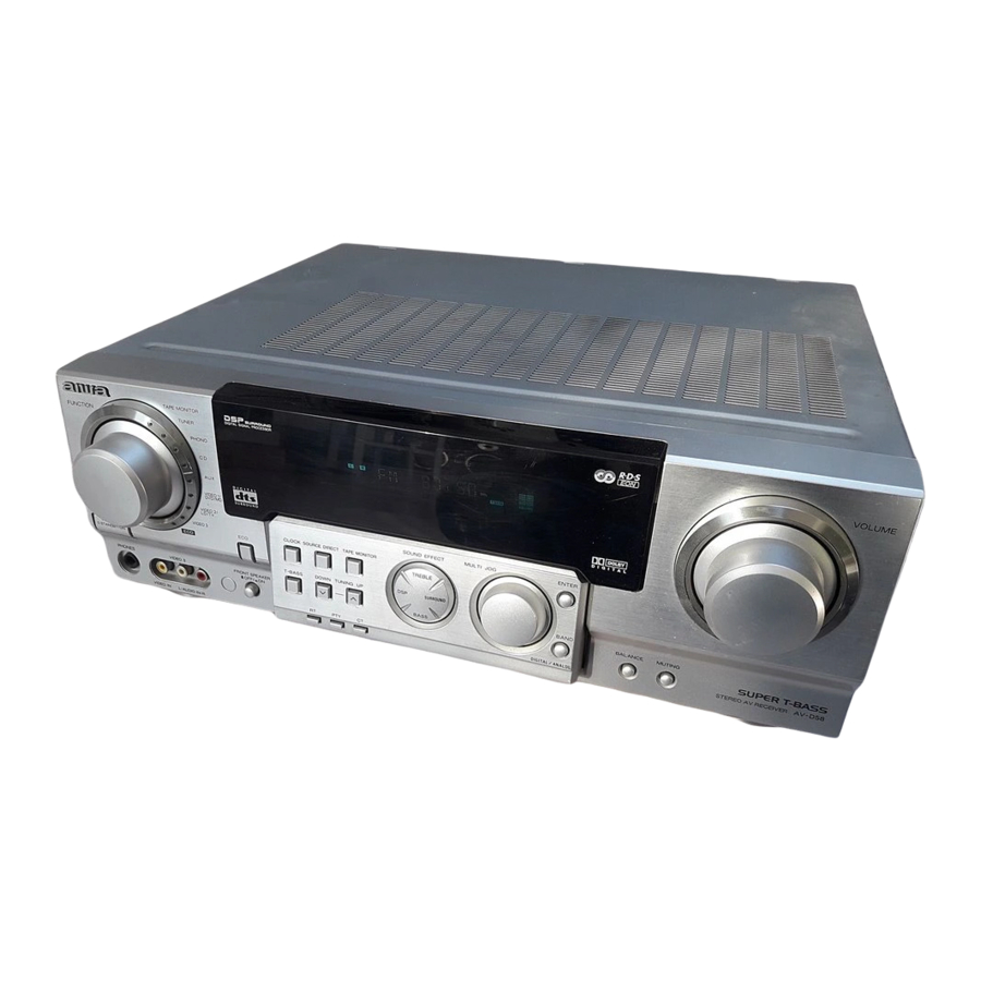
- Page 1 AV-D58 SERVICE MANUAL STEREO RECEIVER • This Service Manual is the "Revision Publishing" and replaces "Simple Manual" AV-D58 (EZ), (S/M Code No. 09-014-444-0T2). S/M Code No. 09-016-444-0R2...
-
Page 2: Specifications
SPECIFICATIONS <FM tuner section> Outputs AUDIO OUT (REC OUT) : 300 mV Tuning range 87.5 MHz to 108 MHz (1 kohm) Usable sensitivity (IHF) 16.8 dBf VIDEO OUT (MONITOR) : 1 Vp-p Antenna terminals 75 ohms (unbalanced) (75 ohms) SUPER WOOFER : 1.5 V <MW tuner section>... -
Page 3: Electrical Main Parts List
ELECTRICAL MAIN PARTS LIST REF. NO. PART NO. KANRI DESCRIPTION REF. NO. PART NO. KANRI DESCR PTION 87-A40-780-080 ZENER,UZ33BSD 87-A40-747-080 ZENER,UZ5.1BSB 87-A21-760-040 C-IC,NJM4580V 87-A40-752-080 ZENER,UZ6.2BSC 8B-AR3-602-030 C-IC,UPD780228GF-084 87-A40-764-080 ZENER,UZ10BSC 87-A21-831-010 IC,SPS-422-1-F1 87-A40-740-080 ZENER,UZ3.3BSA 87-020-784-040 C-IC,TC4053BF 87-A21-703-040 C-IC,SN74LV244APW 87-A40-757-080 ZENER,UZ7.5BSC 87-A40-488-080 DIODE,1SS244 87-A21-916-040 C-IC,SN74LV125APW... - Page 4 REF. NO. PART NO. KANRI DESCRIPTION REF. NO. PART NO. KANRI DESCR PTION C315 87-A10-897-080 CAP,E 100-25 BP SME C541 87-A10-293-080 CAP,M 6800P-50 J C316 87-A10-897-080 CAP,E 100-25 BP SME C542 87-A10-293-080 CAP,M 6800P-50 J C317 87-A11-548-080 C-CAP,S 560P-50 KB C543 87-A12-091-080 CAP,E 10-50 SMG...
- Page 5 REF. NO. PART NO. KANRI DESCRIPTION REF. NO. PART NO. KANRI DESCR PTION R211 87-A00-571-050 RES,M/F 0.15-2W J RZ C156 87-012-195-080 C-CAP,U 100P-50 CH R212 87-A00-571-050 RES,M/F 0.15-2W J RZ C157 87-012-195-080 C-CAP,U 100P-50 CH R215 87-A00-571-050 RES,M/F 0.15-2W J RZ C158 87-012-195-080 C-CAP,U 100P-50 CH...
- Page 6 REF. NO. PART NO. KANRI DESCRIPTION REF. NO. PART NO. KANRI DESCR PTION S314 87-A90-095-080 SW,TACT EVQ11G04M C908 87-012-165-080 C-CAP,U 3P-50 C CH S315 87-A90-095-080 SW,TACT EVQ11G04M C909 87-012-272-080 C-CAP,U 680P-50 KB S316 87-A90-095-080 SW,TACT EVQ11G04M C910 87-012-164-080 C-CAP,U 2P-50 C CH S318 87-A90-095-080 SW,TACT EVQ11G04M...
- Page 7 REF. NO. PART NO. KANRI DESCRIPTION REF. NO. PART NO. KANRI DESCR PTION L904 86-ZA1-613-010 COIL,FM ANT/RF-2-Z C209 87-A12-091-080 CAP,E 10-50 SMG L905 86-ZA1-612-010 COIL,FM ANT/RF-1-Z C210 87-A12-091-080 CAP,E 10-50 SMG L906 87-005-847-080 COIL,2.2UH(CECS) C211 87-012-195-080 C-CAP,U 100P-50 CH L907 86-ZA1-614-010 COIL,FM OSC-Z C212...
- Page 8 REF. NO. PART NO. KANRI DESCRIPTION REF. NO. PART NO. KANRI DESCR PTION C805 87-A12-088-080 CAP,E 2.2-50 SMG 87-012-286-080 C-CAP,U 0.01-25 KB C808 87-012-172-080 C-CAP,U 10P-50 D CH CN50 87-009-663-010 CONN,6P VH V C810 87-012-274-080 C-CAP,U 1000P-50 B CN51 87-A61-300-010 CONN,4P V VH C818 87-010-759-080...
-
Page 9: Chip Resistor Part Code
CHIP RESISTOR PART CODE Chip Resistor Part Coding Figure Resistor Code Value of resistor Chip resistor Dimensions (mm) Wattage Type Tolerance Symbol Resistor Code Form 1/16W 1005 0.35 1/16W 1608 0.45 1/10W 2125 1.25 0.45 1/8W 3216 0.55 TRANSISTOR ILLUSTRATION E C B E C B B C E... -
Page 10: Wiring - 1 (Main)
WIRING – 1 (MAIN) – 10 –... - Page 11 SCHEMATIC DIAGRAM – 1 (MAIN 1 / 2) – 11 –...
- Page 12 SCHEMATIC DIAGRAM – 2 (MAIN 2 / 2) – 12 –...
-
Page 13: Wiring - 2 (Front)
WIRING – 2 (FRONT) – 13 –... - Page 14 SCHEMATIC DIAGRAM – 3 (FRONT) – 14 –...
- Page 15 WIRING – 3 (TUNER) – 15 –...
- Page 16 SCHEMATIC DIAGRAM – 4 (TUNER) – 16 –...
- Page 17 WIRING – 4 (HP / VIDEO / VOLUME / SPEAKER) – 17 –...
- Page 18 SCHEMATIC DIAGRAM – 5 (HP / VIDEO / VOLUME / SPEAKER) – 18 –...
- Page 19 WIRING – 5 (DIGITAL) – 19 –...
- Page 20 SCHEMATIC DIAGRAM – 6 (DIGITAL) – 20 –...
- Page 21 WIRING – 6 (AMP) – 21 –...
- Page 22 SCHEMATIC DIAGRAM – 7 (AMP) – 22 –...
- Page 23 WIRING – 7 (PT / AC OUTLET) – 23 –...
- Page 24 SCHEMATIC DIAGRAM – 8 (AC OUTLET / PT) – 24 –...
- Page 25 FL (HNA-12SM12 BAR-3) GRID ASSIGNMENT / ANODE CONNECTION GRID ASSIGNMENT ANODE CONNECTION – 25 –...
-
Page 26: Ic Block Diagram
IC BLOCK DIAGRAM – 26 –... - Page 27 – 27 –...
- Page 28 IC DESCRIPTION IC, UPD780228GF-084 Pin No. Pin Name Description O-K-SCAN Switch scan timing output. TUNER ON Tuner ON/OFF output. O-DATA(M) Data output for sound. Connected to a pulled up resistor. O-STB(M) Latch strobe output for sound control. O-MUTE System mute ON/OFF output.. O-CLK (M) Clock output.
- Page 29 Pin No. Pin Name Description HOLD Power failure detected input "L" to stop and hold memory. I-RE-VOL Volume rotary encoder signal input (Main vol L & R). RDS-SIG RDS signal level input. I-JOG2 Multi jog rotary encoder signal input. I-FU-JOG1 Function rotary encoder signal input.
- Page 30 ADJUSTMENT <TUNER / FRONT> < TUNER SECTION > 9. LW Tracking Adjustment 1. Clock frequency Check Settings : • Test point : TP8(Rch), TP9(Lch) Settings : • Test point : TP2 (CLK) • Adjustment location : Method : Set to MW 1602kHz and check that the test point is 2052kHz ±...
-
Page 31: Mechanical Exploded View
MECHANICAL EXPLODED VIEW 1 / 1 BINDER, WIRE HT-SINK, TR DD BINDER, WIRE SHLD-CASE, WIRE, HT-SINK BZA-3 P-EZ TR VM SHLD-CASE, HT-SINK, BZA-3 EZ TR VCC TR(B1370) ASSY PLATE EARTH HT-SINK ASSY SHLD-CASE, BZA-3 S-EZ2 CHAS, MAIN WIRE, PLATE, BOTTOM WIRE, –... -
Page 32: Mechanical Parts List
CONN ASSY,2PAC-OUTLET 8 8A-AR3-047-010 RING,FUN 43 88-805-033-690 CONN ASSY,3P 300 9 8A-AR3-009-010 REFLECTOR,FUN 44 88-805-036-010 CONN ASSY,3P 10 87-CE3-023-010 BADGE,AIWA 30N SILV 45 87-A90-762-010 F-BEAD,3407MFT 11 8B-AR1-055-010 KEY,SOUND 46 87-450-414-010 TERMINAL,LB4 NI 12 8B-AR3-022-010 CABI,FR EZ 47 8B-AR1-618-110 PWB,FFC2 BAR-1... -
Page 33: Accessories / Package List
ACCESSORIES / PACKAGE LIST REF. NO. PART NO. KANRI DESCRIPTION 1 8B-AR3-906-010 IB,EZ(9L)M 2 87-006-226-010 ANT,LOOP AM 3 87-A90-118-010 ANT,WIRE FM(Z) 4 8A-AR2-701-110 RC UNIT,RC-AAR02 BLK – 33 –... - Page 34 2–11, IKENOHATA 1–CHOME, TAITO-KU, TOKYO 110, JAPAN TEL:03 (3827) 3111 9620450 921338 Printed in Singapore...