
Related Manuals for Auto Meter SB-5


Summary of Contents for Auto Meter SB-5
-
Page 1: Instruction Manual
SB-5 Battery Load Tester Instruction Manual Simplified Check Program for Charging Systems The SB-5 is a variable load battery tester that provides a simplified check for alternator output and starter draw and circuit test. -
Page 2: Equipment Equipment Needed
Whenever a component fails, the whole system should be checked to insure that the failure was not caused by another part of the system. The SB-5 model is a simplified approach to test each component of the electrical system. This insures that you will be making only the necessary repairs, resulting in satisfied customers and increased business. -
Page 3: Table Of Contents
TABLE OF CONTENTS Equipment Needed----------------------------------------------------2 Equipment Needed----------------------------------------------------2 Specifications -----------------------------------------------------------3 Specifications -----------------------------------------------------------3 Safety ---------------------------------------------------------------------4 Safety ---------------------------------------------------------------------4 Cause of Battery Failure ---------------------------------------------4 Cause of Battery Failure ---------------------------------------------4 Battery Check and Visual Inspection -----------------------------5 Battery Inspection and Visual Check -----------------------------5 Preliminary Notes ------------------------------------------------------6 Preliminary Notes ------------------------------------------------------6 Controls and Functions-----------------------------------------------7... -
Page 4: Safety Safety
SAFETY Carefully read all operating instructions before using the tester Wear eye protection when working around batteries. Be sure each test is completed before removing load clamps to prevent arcing and potential explosion from battery gasses. Never remove load clamps while testing. -
Page 5: Battery Check And Visual Inspection Battery Inspection And Visual Check
BATTERY INSPECTION Valid automotive electrical system testing depends on all the components being in good operating condition. In addition, the battery MUST have sufficient charge for testing. Carefully perform the following before attempting any electrical diagnosis. VISUAL CHECK Inspect Battery for terminal corrosion, loose or broken posts, cracks in the case, loose hold- downs, low electrolyte level,... -
Page 6: Preliminary Notes Preliminary Notes
PRELIMINARY NOTES 1. MOISTURE If tester has not been used for a period of time, moisture may have condensed between carbon pile discs. This will cause the tester to steam a little during first or second load application. This is normal and is not a malfunction of the tester. -
Page 7: Controls And Controls And Functions
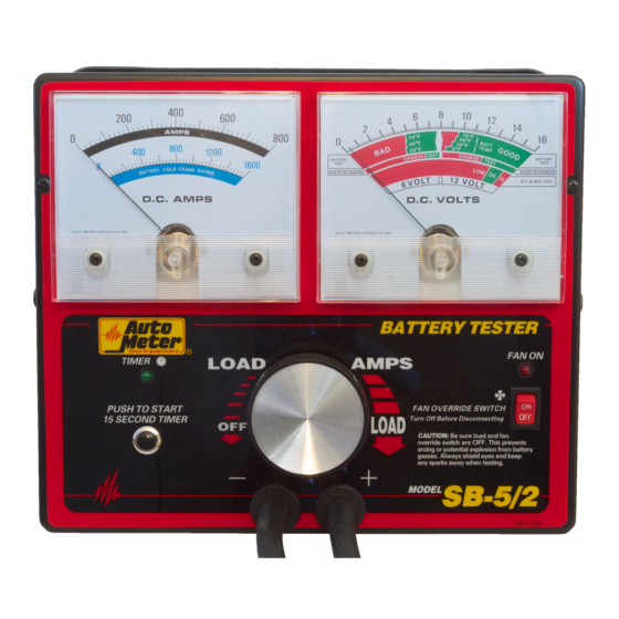
CONTROLS AND FUNCTIONS FAN OVERIDE LIGHT TIMER LIGHT LOAD KNOB FAN OVERIDE SWITCH TIMER PUSH BUTTON TIMER LIGHT: Indicates timer is on. 15 SECOND TIMER BUTTON: Push to start the 15 second timer. LOAD KNOB: Turns the fan on and controls the amount of load during the test. FAN OVERRIDE ON LIGHT: Indicates when the fans override switch is on. -
Page 8: Battery State Of Charge Battery State Of Charge
BATTERY STATE OF CHARGE The battery must have an adequate state of charge before a valid battery load test can be performed. The state of charge can be measured with a hydrometer (see Appendix A page 16), or checked by the “state of charge”... -
Page 9: Battery Load Test Battery Load Test
BATTERY LOAD TEST 1. Turn load knob to apply a load equal to 1/2 the Cold Crank rating or 3 times the Amp-Hour rating for 15 seconds. 2. Hold proper load for 15 seconds, observe the voltage reading, and then immediately decrease the load until the fan stops and the ammeter reads zero. -
Page 10: Starter Draw Test Starter Draw Test
STARTER DRAW TEST For proper starter functioning, it is important that all related connections are clean and tight, and that the cable and its insulation are in good condition. On all starter circuit tests, disable ignition circuit by one of the following methods: •... - Page 11 STARTER DRAW TEST CONT. Example: 1. With ignition disabled crank vehicle and observe lowest volt reading. For this example, we’ll say it reads 11 volts. 2. Apply a load with the Load knob until voltmeter reads 11 volts (see example page 10). Quickly read the ammeter. In this case it reads 240 amps.
-
Page 12: Alternator Test Alternator Test
ALTERNATOR TEST To charge a battery, the alternator must produce a voltage higher than the battery voltage to cause current to flow into it. Therefore, the voltage must rise to the “OK” test zone of the ALT. & REG. TEST band. Before testing, run the vehicles engine at fast idle with all the accessories off for at least 5 minutes to recharge the battery and to stabilize the temperature of the alternator. - Page 13 Troubleshooting Alternator (Hypothetical Situation) Problem: Customer returns continually because his battery keeps running down, but all battery and alternator tests pass. Solutions: • If alternator reads in the low end of the OK range, it is working fine. For people driving short distances, however, the battery may not charge fast enough, causing the battery to run down slowly.
-
Page 14: Starter Circuit Test Starter Circuit Test
STARTER CIRCUIT TEST Disable ignition as indicated in the Starter-Draw Test on page 10. 1. Connect the tester as shown below. A with the RED clamp to battery positive and the BLACK clamp to the terminal on the starter, which is connected to the solenoid directly or by cable. - Page 15 6. To check the ground circuit, connect the RED clamp directly to the starter casing (this may require chipping paint to make a good connection), and the BLACK clamp to the battery negative terminal as shown in example below. BLACK 7.
- Page 16 APPENDIX HYDROMETER METHOD Check the electrolyte specific gravity with a hydrometer. If the specific gravity measures between 1.100 and 1.220, the battery must be recharged. If the specific gravity is between 1.225 and 1.265, the battery is ok to test. If the hydrometer has a temperature correction chart, be sure to adjust the reading for the battery’s temperature.
-
Page 17: Battery Charging Guide Battery Charging Guide
APPENDIX BATTERY CHARGING GUIDE (6 and 12 Volt Batteries) Recommended charging rate and time for fully discharged batteries. Par- tially discharged batteries will require less charging time. BATTERY CATEGORY CHARGE BATTERY (RESERVE CAPACITY MINUTES) At either rate and time shown 14 hrs. -
Page 18: Appendix C Multiple Battery System Tests Appendix C Multiple Battery System Tests
APPENDIX MULTIPLE BATTERY SYSTEM TESTS In heavy duty applications, 6 and 12 volt charging systems are created by combining 6 and 12 Volt batteries in various combinations. For a valid test, batteries must be tested individually, and the charging system must be tested at its rated voltage (6 or 12 Volts). CAUTION: Care must be taken when disconnecting battery cables to prevent shorting of loose cables to ground or positive. - Page 19 ALTERNATOR TESTS BLACK 12 Volt System Test Using Two 6 Volt Batteries In Series 6 Volts 6 Volts 6 Volts Using the hookup above follow test procedures on page 12. BLACK RED 6 or 12 Volt System Tests Using Single Or Multiple Batteries Connected In Parallel Use the scale appropriate for the system test.
-
Page 20: Service Service Information
SERVICE INFORMATION Warranty claims to Auto Meter must be transportation prepaid and accompanied by dated proof of purchase. This warranty applies only to the original purchaser and is non-transferable. Damage incurred during return shipment is not covered under this warranty. It is the responsibility of the shipper (customer returning tester) to package the tester properly to prevent damage during return shipment. - Page 21 Cardboard load holder for shipping In the event your tester needs to be returned to Auto Meter for service, it must be properly packaged and protected to avoid damage during shipment. Failure to follow these steps will allow the carbon disks to rattle freely during shipment and cause breakage.
-
Page 22: Clamp Inspection And Maintenance Clamp Inspection And Maintenance
CLAMP INSPECTION and MAINTANENCE IMPORTANT: Both jaws of each clamp must firmly engage terminals. The copper jaw contains CHECK OFTEN FOR LOOSE JAWS the smaller gauge wire that OR DAMAGED INTERNAL PLASTIC reads the voltage and the SHOULDER INSULATORS silver jaw contains the larger conducting wire that draws the load in each test. -
Page 23: Warranty Warranty
This warranty is limited to the repair or replace- ment of parts in the tester and the necessary labor by Auto Meter to affect the repair or replacement of the tester. In no event shall this warranty exceed the original purchase price of the tester, nor shall Auto... -
Page 24: Contact Information Contact Information
• To return to this page navigate to last page. • Press ESC to Exit full view. Auto Meter Products Inc. 350 West Center Street Pleasant Grove, Utah 84062 Service (801) 785-0051 ext. 223 �...
Need help?
Do you have a question about the SB-5 and is the answer not in the manual?
Questions and answers