Table of Contents
Advertisement
Quick Links
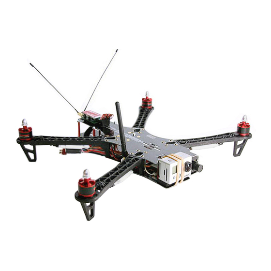
TBS DISCOVERY Quadrotor
Durable and crash resistant multirotor optimized for
dynamic FPV flight
Revision 2014-09-21
The TBS DISCOVERY quadcopter is a durable and crash resistant multirotor
optimized for dynamic FPV flight. By implementing the wiring into the frame,
the copter is easy to build and outperforms similar quads in terms of FPV
range and video link quality. It is perfect for all looking at a durable and
highly integrated FPV solution. The DJI Flame Wheel arms as predetermined
breaking point protect your electronics and are easily replaceable in the
field.
The TBS DISCOVERY comes as two main boards (top and bottom) and optional Flame Wheel arms with
accessories. It transforms the popular F450 (Flame Wheel) into a spider quadrotor. The GoPro and FPV camera
mount is placed ideally for "no-prop-in-view" pictures. The optional TBS CORE can be placed directly onto the
frame or we can install it for you.
Features
●
TBS CORE pre-wired incl. sockets for Plug&Play VTx and FPV camera installation
50A Current Sensor installed on the board, built for the TBS CORE or similar OSDs
●
●
GoPro and FPV camera mounts
Power Distribution Board (PDB)
●
●
Traces and pads for clean R/C receiver to Flight Controller wiring
●
RSSI trace to the TBS CORE
1
Advertisement
Table of Contents

Subscribe to Our Youtube Channel
Related Manuals for tbs electronics Discovery


Summary of Contents for tbs electronics Discovery
- Page 1 The TBS DISCOVERY comes as two main boards (top and bottom) and optional Flame Wheel arms with accessories. It transforms the popular F450 (Flame Wheel) into a spider quadrotor. The GoPro and FPV camera mount is placed ideally for "no-prop-in-view"...
-
Page 2: Before We Begin
Before we begin Thank you for buying a TBS product! The TBS DISCOVERY is a new multirotor aircraft from Team BlackSheep (TBS) and features the best design practices available on the market to date, providing great flying stability and incredible FPV characteristics. -
Page 3: Specifications
Specifications Type: Asymmetric spider quadrotor Airframe: Reinforced black fiberglass (top RF transparent, bottom PDB) Battery: 3S (11.1V) 5000 to 6000mAh or 4S (14.8V) 2500 to 4500mAh LiPo pack Propellers: 9x5-inch or 10x5-inch (2xCW, 2xCCW) Motor: 2212 or 2216 class, 700-900kV, 150-220W, 16x19 mm mount pattern Speed controllers: 18 to 30A 400Hz Multirotor ESCs Receiver:... -
Page 4: Parts List
Parts list Before building your TBS DISCOVERY, make sure the following items are included in your kit. 1x Top frame plate 1x Bottom frame plate 1x Pilot camera mount plate 8x Red aluminum spacers 36x M3x6.5mm hex fitting screws 30x M2.5x5mm hex frame arm... - Page 5 4x 9x5 or 10x5-inch propellers 1x 3S 5000 to 6000mAh or 4S 2800 1x Multicopter flight controller (2xCW, 2xCCW) to 4500mAh LiPo battery 1x R/C receiver (5-channels or 1x R/C transmitter (5-channels or 1x LiPo battery charger more) more) 1x Pilot camera (32x32mm) 1x HD recording camera ...
- Page 6 Frequency choice Frequency choice depends on the ranges you want to fly. Using 5.8GHz video is an ideal frequency if you do not plan on flying far away from yourself or behind objects. It is compatible with 2.4GHz remote controls. Using 2.4GHz video (TBS video frequency of choice) will give you nearly unlimited range and far superior link quality, but you can not use your 2.4GHz remote control on the same quad because of limited separation (it is no problem for our R/C buddies to fly with 2.4GHz remote controls next to you though!).
-
Page 7: Choosing The Right Setup
Use these suggested setups as a “shopping list” if you are just getting started. Any existing gear you already own (e.g. remote controls, chargers, batteries) can be used with the TBS DISCOVERY. These setups, with the exception of the Camera Tripod and the Remote Control, are available from Team BlackSheep. - Page 8 TBS DISCOVERY setup for long range flights Expected flight time: 8-12 min ● ● Cost range: US$ 2’000 - US$ 2’800 ● Experience level: Expert Ideal for: Long, wide open fields, plains, coastlines and valleys or urban flying ● R/C transmitter/receiver:...
-
Page 9: Frame Assembly
Frame assembly Begin by assembling the base of the frame and soldering the speed controller, battery lead and flight controller to the bottom power distribution board (PDB). In addition to the following assembly instructions, we have a professionally produced “How To”-video on our website showing the assembly and electronics installation. - Page 10 DRAWN TBS Associates Inc 31.07.2013 CHECKED TITLE APPROVED SIZE DWG NO tbs_discovery_pro_frame SCALE SHEET...
- Page 11 Spacers ● Next, add the red spacers (posts) to the bottom frame plate using the supplied M3x6.5mm hex screws. Add a small drop of threadlock to help secure the frame. It is recommended to only apply on the bottom screws for easy repairs/maintenance. ●...
- Page 12 Top plate R/C control signal headers ● To get a clean R/C receiver-to-flight controller wiring, it is recommended to use the traces routed on the top plate. There are 8 traces to support up to equally many PWM (Pulse Width Modulation) channels. When using a PPM (Pulse Position Modulation) compatible receiver and flight controller, only one trace (Channel 1) is used.
-
Page 13: Electronics Installation
Electronics installation The electronics installation is split into two sections; one for the R/C equipment and the second for the FPV gear. We recommend finishing and dry-testing the R/C system before moving on to the FPV section to simplify troubleshooting. A detailed overview diagram of the electronics installation is available as an appendix to this manual. - Page 14 Electronics installation Top frame (Optional) by ivc.no/tbsdiscovery - 08.2013 8 7 6 5 4 3 2 1 RC receiver S + - TBS DISCOVERY (For channel setup, refer to the manufacurer’s manual) Video transmitter BEC regulator Flight controller Motor - CW...
- Page 15 ● (DJI NAZA only) Open NAZA Assistant and disable the Voltage Monitor Protection. This prevents the DISCOVERY PRO from prematurely descending on low battery. Use the CORE OSD to watch the battery condition instead. Never let the voltage go past 3.5V x cell count (3S 10.5V, 4S 14.0V) or current consumption over 80% of a full pack (e.g.
- Page 16 Speed controllers ● With the frame arms mounted, use the zip-ties to mount the speed controllers to the underside of the arms. Avoid putting tension or stress on the motor- or speed controller-cables. Use a self-adhesive pad to mount any BEC or control unit (e.g. NAZA PMU/VU-unit.) to the underside of the back-left speed controller.
- Page 17 ● A thumb of rule would be that smaller props equals less flight time and higher kV motors equals smaller props or lower battery cells count (than the reference below.) Note that 10-inch is the maximum propeller size that can fit on the DISCOVERY. Motor type ...
- Page 18 FPV gear The FPV gear is designed to be installed on the front section of the frame to achieve as much separation between the R/C- and FPV-radio environment as possible. Keep in mind that the former is listening while the latter is broadcasting.
- Page 19 Video transmitter ● Put the video transmitter close to the front on the top plate. Use zip-ties and/or self-adhesive foam pads to fit the transmitter. TBS offers a custom made mounting bracket for easy vertical install over the front-right frame arm. ●...
- Page 20 TBS DISCOVERY / DISCOVERY PRO - Video transmitter (VTx) setups rev. Feb 2014 - by ivc.no/tbs TBS/Lawmate VTx Boscam VTx · 1.2G 500mW · 2.4G 500mW · 2.4G 100mW, 200mW, 500mW · 5.8G 200mW, 400mW, 500mW · 5.8G 25mW (TBS Greenhorn), 200mW (TBS Rookie), 500mW (TBS Boss) Supply voltage: 5.0-5.5V (all)
- Page 21 ● To enable the CORE OSD, solder a dab between the two pads labeled “OSD Enable” on the TBS CORE board. ● The bottom plate has a RSSI trace leading directly to TBS CORE. The RSSI input header is located on the middle-left side, right beneath the top pin header for easy connection directly from a supported R/C receiver.
-
Page 22: Mounting Hd Camera
● The GoPro HD Hero cameras is the most commonly used HD recording camera (as of writing) and was the camera of choice during the design process of the TBS DISCOVERY. ● A little background how modern HD video cameras function; the GoPro uses a method called rolling... - Page 23 GoPro HD Hero1: Video format: NTSC to get 30fps Video resolution: 1080p 30fps (medium angle) for 10x5-inch props 720p 30fps (wide angle) for 9x5-inch props GoPro HD Hero2: Video format: NTSC to get 30fps Video resolution: 1080p 30fps high quality video Video angle: ...
- Page 24 Center of Gravity optimization ● A properly balanced multirotor will distributing the weight (mass) equally over the four motors. The mark on the bottom plate is the Center of Thrust (CT, CoT) mark and the Center of Gravity (CG, CoG) spot is 15mm forward of this mark.
- Page 25 Center of Gravity diagram by ivc.no/tbsdiscovery - 02. 2013...
-
Page 26: First Flight
Flight First flight Check that the flight battery and transmitter battery is fully charged. Make sure all the screws on the frame and the propellers are secured, and that the battery strapped down. Balance the quadcopter around the Center of Gravity (CG) spot by repositioning the battery. -
Page 27: Good Practices
Good practices We have compiled a list of all of the things that have been tried and tested in countless environments and situations by TBS crew and other experienced FPV pilots. Follow these simple rules, even if rumors on the internet suggest otherwise, and you will have success in FPV. ●... - Page 28 ● Try to achieve as much separation of the VTx and R/C receiver as possible to lower the RF noise floor and EMI interference. Do not buy the cheapest equipment unless it is proven to work reliably (e.g. parts falling off, multitudes ●...
-
Page 29: Troubleshooting
Troubleshooting Issue: Horizontal lines in pilot video downlink ● Solution: If there are lines in the video during flight that disappear as soon as you land, your video transmitter is exposed to too much vibrations. Memory foam in conjunction with the Flame Wheel VTx mount will take out the vibrations in an instant and give you crystal-clear video. -
Page 30: Recommended Parts
Recommended parts Below is a list of compatible R/C and FPV gear for the TBS DISCOVERY quadrotor. This will hopefully make it easier to pick up spare parts and upgrades. Power sets TBS 750kV Motor / ESC Combo A very sweet Motor/ESC combination which offers great value. - Page 31 Flight controller DJI NAZA-M with optional GPS ● ● OpenPilot CopterControl 3D R/C Transmitter/Receiver ● Futaba 8FG / 7C with included receiver R6208SB / R617FS ● Graupner MX-12 radio with included GR-6 receiver ● ImmersionRC EzUHF 8ch Diversity receiver ● ImmersionRC EzUHF 8ch Lite receiver Propellers ●...
-
Page 32: Spare Parts
Spare parts You can either get spare parts directly from us (team-blacksheep.com) or from one of our distributors and retailers near you. Our ever-growing list of retailers is published on the left at team-blacksheep.com/shop. - Page 33 Appendix Frame assembly diagram ● ● Electronics installation diagram ● Video transmitter installation diagram Center of Gravity diagram ● Manual written and designed by ivc.no in cooperation with TBS.
Need help?
Do you have a question about the Discovery and is the answer not in the manual?
Questions and answers