Table of Contents
Advertisement
CONTENTS
SAFETY CONSIDERATIONS . . . . . . . . . . . . . . . . . . . . . . 1
INSTALLATION . . . . . . . . . . . . . . . . . . . . . . . . . . . . . . . . 1-46
Step 1 - Provide Unit Support . . . . . . . . . . . . . . . . . . . 1
• ROOF CURB
• ALTERNATE UNIT SUPPORT
Step 2 - Rig and Place Unit . . . . . . . . . . . . . . . . . . . . . 1
• POSITIONING
Step 3 - Field Fabricate Ductwork . . . . . . . . . . . . . . . 2
Step 4 - Make Unit Duct Connections . . . . . . . . . . . 2
Step 5 - Trap Condensate Drain . . . . . . . . . . . . . . . . 18
Step 6 - Make Electrical Connections . . . . . . . . . . 18
• POWER WIRING
• FIELD POWER SUPPLY
• FIELD CONTROL WIRING
Step 7 - Make Outdoor-Air Inlet
Adjustments . . . . . . . . . . . . . . . . . . . . . . . . . . . . . . . . . . 42
Relief Damper Hood. . . . . . . . . . . . . . . . . . . . . . . . . . . 44
Step 9 - Route Static Pressure Sensors . . . . . . . . 45
Step 10 - Install All Accessories . . . . . . . . . . . . . . . 45
Step 11 - Field Modifications. . . . . . . . . . . . . . . . . . . 46
SAFETY CONSIDERATIONS
Installation and servicing of air-conditioning equipment can
be hazardous due to system pressure and electrical compo-
nents. Only trained and qualified service personnel should in-
stall, repair, or service air-conditioning equipment.
Untrained personnel can perform the basic maintenance
functions of cleaning coils and filters and replacing filters. All
other operations should be performed by trained service per-
sonnel. When working on air-conditioning equipment, observe
precautions in the literature, tags and labels attached to the unit,
and other safety precautions that may apply.
Follow all safety codes. Wear safety glasses and work
gloves. Use quenching cloth for unbrazing operations. Have
fire extinguishers available for all brazing operations.
Before performing service or maintenance operations on
unit, turn off main power switch to unit. Electrical shock
could cause personal injury.
PC 111
Book 1
Tab
1b
Electric Cooling with Electric Heat Option
Installation Instructions
Page
Catalog No. 535-00075
Printed in U.S.A.
50AJ,AK,AW,AY020-060
With Scroll Compressor and
ComfortLink™ Control
Single Package Rooftop Units
1. Improper installation, adjustment, alteration, service,
or maintenance can cause property damage, personal
injury, or loss of life. Refer to the User's Information
Manual provided with this unit for more details.
2. Do not store or use gasoline or other flammable va-
pors and liquids in the vicinity of this or any other
appliance.
INSTALLATION
Step 1 - Provide Unit Support
1. All panels must be in place when rigging.
2. Unit is not designed for handling by fork truck.
ROOF CURB - For vertical discharge units, assemble or in-
stall accessory roof curb in accordance with instructions
shipped with this accessory. See Fig. 1-4. Install insulation,
cant strips, roofing, and counter flashing as shown. Ductwork
can be installed to roof curb before unit is set in place. Curb
should be level. This is necessary to permit unit drain to func-
tion properly. Unit leveling tolerance is shown in Fig. 1-4.
Refer to Accessory Roof Curb Installation Instructions for
additional information as required. When accessory roof curb
is used, unit may be installed on class A, B, or C roof covering
material.
IMPORTANT: The gasketing of the unit to the roof curb is
critical for a watertight seal. Install gasket with the roof
curb as shown in Fig. 1-4. Improperly applied gasket can
also result in air leaks and poor unit performance.
ALTERNATE UNIT SUPPORT - When the preferred curb
or slab mount cannot be used, support unit with sleepers on
perimeter, using unit curb support area. If sleepers cannot be
used, support long sides of unit (refer to Fig. 5-10) with a mini-
mum number of 4-in. x 4-in. pads spaced as follows:
50AJ,AK,AW,AY020-035 units require 3 pads on each side;
50AJ,AK,AW,AY040-050 units require 4 pads on each side;
50AJ,AK,AW,AY060 units require 6 pads on each side. Unit
may sag if supported by corners only.
Step 2 - Rig and Place Unit -
transportation damage. See Tables 1-3 for physical data and
specifications. File any claim with transportation agency.
Do not drop unit; keep upright. Use spreader bars over unit
to prevent sling or cable damage. This unit must be handled
with a crane and can not be handled by a fork truck. Level by
using unit frame as a reference; leveling tolerance is shown in
Fig. 1-4. See Fig. 11 for additional information. Unit operating
weight is shown in Table 2.
Form 50A-1SI
Pg 1
Inspect
unit
for
7-03
Replaces: New
Advertisement
Table of Contents

Related Manuals for Carrier 50AJ/AK/AM020


Summary of Contents for Carrier 50AJ/AK/AM020
-
Page 1: Table Of Contents
50AJ,AK,AW,AY020-060 With Scroll Compressor and ComfortLink™ Control Single Package Rooftop Units Electric Cooling with Electric Heat Option Installation Instructions CONTENTS Page 1. Improper installation, adjustment, alteration, service, SAFETY CONSIDERATIONS ..... . 1 or maintenance can cause property damage, personal INSTALLATION . -
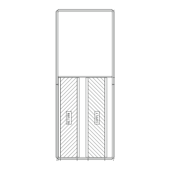
Page 2: Roof Mount
NOTE: On retrofit jobs, ductwork may be attached to old unit instead of roof curb. Be careful not to damage ductwork when removing old unit. Attach existing ductwork to roof curb For vertical supply and return units, tools or parts could instead of unit. - Page 13 Table 1 — Physical Data — 50AJ,AK,AW,AY Units UNIT 50AJ,AK,AW,AY NOMINAL CAPACITY (tons) BASE UNIT See Operating Weights Table OPERATING WEIGHT (lb) COMPRESSOR 1…SR*812AT, Quantity...Type (Ckt 1, Ckt 2) 2…SR*782AT/1…SR*782AE 2...SR*942AT/1…SR*942AE 2…SR*782AT/2…SR*812AT 1…SR*942AT/1…SR*942AE Number of Refrigerant Circuits Oil (oz) (Ckt 1, Ckt 2) Precharged Precharged Precharged...
- Page 14 Table 1 — Physical Data — 50AJ,AK,AW,AY Units (cont) UNIT 50AJ,AK,AW,AY NOMINAL CAPACITY (tons) BASE UNIT See Operating Weights Table OPERATING WEIGHT (lb) COMPRESSOR 1…SR*812AT, 1...SM160,1...SM175/ Quantity...Type (Ckt 1, Ckt 2) 2…SR*942AT/2…SM125 2…SM125/1…SM125, 1…SM175 1…SR*942AT/2…SR*942AT 1...SM160,1...SM175 Number of Refrigerant Circuits Oil (oz) (Ckt 1, Ckt 2) Precharged Precharged...
- Page 16 Table 2 — Operating Weights 50AJ,AK,AW,AY Units BASE UNIT WEIGHTS — lb UNIT 50AJ,AK 3642 3715 3832 3982 4120 4660 5131 7148 50AW,AY 3720 3793 3910 4060 4313 4853 5324 7363 OPTION/ACCESSORY WEIGHTS — lb OPTION/ ACCESSORY Barometric Relief Power Exhaust Mod.
- Page 17 Table 3 — Evaporator Fan Motor Data MOTOR UNIT MOTOR SHEAVE BUSHING SHEAVE BUSHING BELT SIZE MOTOR SHAFT MOTOR BELT SHAFT DIA. PITCH DIAMETER PITCH DIAMETER TENSION 50AJ,AK, SPEED SHEAVE SHEAVE (Quantity) (in.) DIAMETER (in.) DIAMETER (in.) (lb at .25 in.) AW,AY (rpm) (in.)
-
Page 18: Step 5 - Trap Condensate Drain
Step 5 — Trap Condensate Drain — See Fig. 5-10 for drain location. Condensate drain is open to atmosphere and FIELD must be trapped. Install a trapped drain at the drain location. One 1-in. FPT coupling is provided inside the unit evaporator POWER section for condensate drain connection. -
Page 19: Field Control Wiring
After wiring is in control box, make connection to proper Affix crankcase heater sticker (located in the installers terminals on terminal blocks (see Field Control Wiring section packet) to unit disconnect switch. on page 28). Voltage to compressor terminals during compressor opera- tion must be within the voltage range indicated on the unit IMPORTANT: The VAV (variable air volume) units use nameplate. - Page 20 Table 4 — Electrical Data — 50AJ,AK,AW,AY Units COMPRESSOR VOLTAGE CONDENSER EVAPORATOR POWER OPTIONAL POWER UNIT VOLTAGE RANGE FAN MOTOR FAN MOTOR EXHAUST ELECTRIC HEAT SUPPLY Cir A, No. 1 Cir A, No. 2 Cir B, No. 1 Cir B, No. 2 SIZE 3 PH, 60 Hz...
- Page 21 Table 4 — Electrical Data — 50AJ,AK,AW,AY Units (cont COMPRESSOR VOLTAGE CONDENSER EVAPORATOR POWER OPTIONAL POWER UNIT VOLTAGE RANGE FAN MOTOR FAN MOTOR EXHAUST ELECTRIC HEAT SUPPLY Cir A, No. 1 Cir A, No. 2 Cir B, No. 1 Cir B, No. 2 SIZE 3 PH, 60 Hz...
- Page 22 Table 4 — Electrical Data — 50AJ,AK,AW,AY Units (cont COMPRESSOR VOLTAGE CONDENSER EVAPORATOR POWER OPTIONAL POWER UNIT VOLTAGE RANGE FAN MOTOR FAN MOTOR EXHAUST ELECTRIC HEAT SUPPLY Cir A, No. 1 Cir A, No. 2 Cir B, No. 1 Cir B, No. 2 SIZE 3 PH, 60 Hz...
- Page 23 Table 4 — Electrical Data — 50AJ,AK,AW,AY Units (cont) COMPRESSOR VOLTAGE CONDENSER EVAPORATOR POWER OPTIONAL POWER UNIT VOLTAGE RANGE FAN MOTOR FAN MOTOR EXHAUST ELECTRIC HEAT SUPPLY Cir A, No. 1 Cir A, No. 2 Cir B, No. 1 Cir B, No. 2 SIZE 3 PH, 60 Hz...
- Page 24 Table 4 — Electrical Data — 50AJ,AK,AW,AY Units (cont) COMPRESSOR VOLTAGE CONDENSER EVAPORATOR POWER OPTIONAL POWER UNIT VOLTAGE RANGE FAN MOTOR FAN MOTOR EXHAUST ELECTRIC HEAT SUPPLY Cir A, No. 1 Cir A, No. 2 Cir B, No. 1 Cir B, No. 2 SIZE 3 PH, 60 Hz...
- Page 25 Table 4 — Electrical Data — 50AJ,AK,AW,AY Units (cont) COMPRESSOR VOLTAGE CONDENSER EVAPORATOR POWER OPTIONAL POWER UNIT VOLTAGE RANGE FAN MOTOR FAN MOTOR EXHAUST ELECTRIC HEAT SUPPLY Cir A, No. 1 Cir A, No. 2 Cir B, No. 1 Cir B, No. 2 SIZE 3 PH, 60 Hz...
- Page 26 Table 4 — Electrical Data — 50AJ,AK,AW,AY Units (cont) COMPRESSOR VOLTAGE CONDENSER EVAPORATOR POWER OPTIONAL POWER UNIT VOLTAGE RANGE FAN MOTOR FAN MOTOR EXHAUST ELECTRIC HEAT SUPPLY Cir A, No. 1 Cir A, No. 2 Cir B, No. 1 Cir B, No. 2 SIZE 3 PH, 60 Hz...
- Page 27 Table 4 — Electrical Data — 50AJ,AK,AW,AY Units (cont) COMPRESSOR VOLTAGE CONDENSER EVAPORATOR POWER OPTIONAL POWER UNIT VOLTAGE RANGE FAN MOTOR FAN MOTOR EXHAUST ELECTRIC HEAT SUPPLY Cir A, No. 1 Cir A, No. 2 Cir B, No. 1 Cir B, No. 2 SIZE 3 PH, 60 Hz...
-
Page 28: Field Control Wiring
(CV and VAV) and T56 space temperature sensors that use a 10K thermistor. • Network Application with Carrier CCN or other networks The T56 sensor also has the capability for a ± 5 F temperature • Demand Ventilation with CO sensor set point offset at the thermostat. - Page 29 SENSOR 1 SENSOR 4 SENSOR 3 SENSOR 2 SPACE TEMPERATURE AVERAGING (4 SENSOR APPLICATION) SENSOR 1 SENSOR 2 SENSOR 3 SENSOR 6 SENSOR 5 SENSOR 4 SENSOR 9 SENSOR 8 SENSOR 7 SPACE TEMPERATURE AVERAGING (9 SENSOR APPLICATION) NOTE: Use T55 sensor only. Fig.
- Page 30 Remote IAQ Override — If the control is being used with non Fire Shutdown and Smoke Control — The control supports Carrier building management system it supports the use of the interface to fire and smoke control systems and allows for the remote IAQ override switch.
-
Page 31: Field Power Supply
— Circuit Breaker — Outdoor Fan Motor — Control Circuit Breaker — Power Exhaust Contactor — Crankcase Heater — Power Exhaust Motor — Carrier Communication Network — Plug Assembly — Controls Expansion Module — Positive Temperature Coefficient COMP — Compressor Motor Power Reference —... - Page 34 NEXT PAGE NEXT PAGE Fig. 21 — Typical Main Control Box Wiring Schematic...
- Page 35 FROM PREVIOUS PAGE FROM PREVIOUS PAGE Fig. 21 — Typical Main Control Box Wiring Schematic (cont)
- Page 36 NEXT PAGE NEXT PAGE Fig. 22 — Auxiliary Control Box Wiring Schematic...
- Page 37 FROM PREVIOUS PAGE FROM PREVIOUS PAGE FROM PREVIOUS PAGE Fig. 22 — Auxiliary Control Box Wiring Schematic (cont)
- Page 38 Fig. 23 — Typical Power Schematic (Size 060 Unit Shown)
- Page 39 Fig. 23 — Typical Power Schematic (Size 060 Unit Shown) (cont)
-
Page 42: Adjustments
Step 7 — Make Outdoor-Air Inlet Adjustments FLANGE ECONOMIZER AND FIXED OUTDOOR AIR DAMPER Hoods are used on all units with economizer or adjustable self- BLACK closing fixed outdoor air damper. HOOD SIDE SEAL STRIP NOTE: If accessory power exhaust or barometric relief pack- ages are being added to the unit, install power exhaust or baro- metric relief before installing economizer hoods. - Page 43 HOOD TOP HOOD SIDE BLOCKOFF BAFFLE GRAY FOAM STRIP Fig. 29 — Adding Seal Strip to Back of Hood Top Mounting Flange GRAY FOAM STRIP Fig. 32 — Adding Seal Strip to Blockoff Baffle 11. Assemble 2 filter tracks side-by-side with the assembled ends together.
-
Page 44: Step 8 - Position Power Exhaust/Barometric
BLACK SEAL STRIP MOUNTING ANGLE (CENTERED) (WITHOUT TABS) FILTER TRACK ASSEMBLY FILTER COVER Fig. 33 — Mounting Angle (Without Tabs) Attached to Filter Track Assembly Fig. 35 — Attaching Seal Strip to Filter Cover Step 8 — Position Power Exhaust/Barometric Relief Damper Hood —... -
Page 45: Step 9 - Route Static Pressure Sensors
1. Remove 9 screws holding each damper assembly in Step 10 — Install All Accessories — After all the place. See Fig. 37. Each damper assembly is secured with factory-installed options have been adjusted, install all field- 3 screws on each side and 3 screws along the bottom. installed accessories. -
Page 46: Step 11 - Field Modifications
There are 2 panels on 50AJ,AK020- Management Systems, not typically needed on system with 050 units. There are 3 panels on 50AJ,AK060 and units. the Carrier Comfort Network [CNN]) These openings are normally used for power exhaust or • Plugged Filter Sensor barometric relief. -
Page 48: Manufacturer Reserves The Right To Discontinue, Or Change At Any Time, Specifications Or Designs Without Notice And Without Incurring Obligations
Copyright 2003 Carrier Corporation Manufacturer reserves the right to discontinue, or change at any time, specifications or designs without notice and without incurring obligations. Book 1 PC 111 Catalog No. 535-00075 Printed in U.S.A. Form 50A-1SI Pg 48 8-03A 7-03...
Need help?
Do you have a question about the 50AJ/AK/AM020 and is the answer not in the manual?
Questions and answers