
Related Manuals for Thermomax SMX 100

Summary of Contents for Thermomax SMX 100
- Page 1 THERMOMAX SMX 100 Microprocessor Based Refrigeration Controller Datalogger and Alarm ENGLISH www.Thermomax-Group.com...
-
Page 2: Table Of Contents
3.8.1 Transferring Data Using the Masterlink Software ..............23 3.8.2 Transferring Data to the Masterlink Hardware .. 23 3.8.3 Printing Data to the Thermomax Serial Printer .. 25 3.9 - DATA TRANSFER - Panelmount units Only ....26 SECTION 4 - FAULT FINDING ..............……..30 SECTION 5 - SPECIFICATIONS ............……..…... -
Page 3: Section 1 - Introduction
SECTION 1 - INTRODUCTION The SMX 100 microprocessor-based system uses modern technology to ensure that the cold-room is controlled and monitored with the greatest of ease. The large graphics LCD display communicates the information to the user with clarity, making programming and setting up friendly and uncomplicated, without compromising its sophistication and digital accuracy. -
Page 4: Section 2 - Installation
SECTION 2 – INSTALLATION NOTE: This installation procedure is for guidance only, and its suitability should be verified by the installer. It is assumed that the refrigeration plant is physically installed and tested, and is ready for operation and connection to the electric supply. SAFETY PRECAUTIONS The following safety precautions are strongly recommended: Before attempting to install and operate the unit, read this instruction manual... -
Page 5: Smx 100 Unit
2.1.2 Fasten the screw corresponding to the top centre lug on the back of the SMX 100 unit, into the wall or panel on which the control box is to be mounted. Leave a gap of approximately 3mm between the screw head and the wall. -
Page 6: Alarm Relay
2.2.3 Install the product sensor either to measure the air temperature or product temperature (or simulated product), as required, depending on the application. The SMX 100 uses the temperature measured by this sensor for logging purposes only. ALARM RELAY NOTE: The alarm relay is a 3 contact changeover arrangement which is isolated (volt-free). -
Page 7: Battery
1 hour, and maintaining the system clock. If a longer period of mains failure is anticipated, a battery kit of up to 72 hours capacity can be supplied by Thermomax. If the power cut takes longer and the battery has discharged, the clock must be reset when the power supply is re-established. -
Page 8: Section 3 - Smx 100 Operation
SECTION 3 - SMX 100 OPERATION In order to fully understand the operation of the SMX 100, this section should be read carefully. 3.1 - DESCRIPTION GRAPHICS LCD DISPLAY Displays all the information. The contrast is adjustable to suit the user. - Page 9 SET KEYS keys are used to set the value of any selected parameter, by increasing and decreasing the value respectively. In most of the functions, described later in the manual, the keys have an auto-repeat facility: press and hold the key in order to advance quickly.
-
Page 10: Main Screen
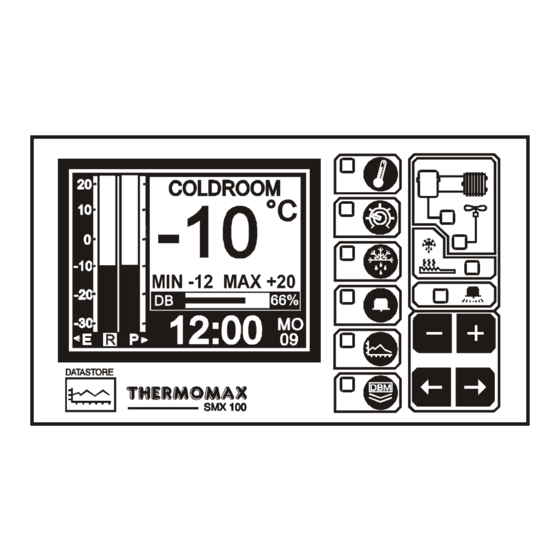
MAIN SCREEN 3.2.1 MAIN INFORMATION DISPLAYS MAIN function selector. Clock display: 24-hour format with day of week abbreviation. Cold-room temperature bargraph display. Product temperature bargraph display. Display select indicator. The highlighted box indicates which temperature is displayed. The options are : E - Evaporator R - Room (cold-room) P - Product (temperature used for logging purposes... -
Page 11: Set Screens
SET SCREENS 3.3.1 SET SCREEN 1: CLOCK / CALENDAR SCREEN SET SCREEN function selector The datalogging system uses the calendar to file the logged data. Selection indicator The highlighted parameter is adjusted by pressing the key. . (The selections are: ‘year’, ‘month’, ‘day’(↑), ‘hour’ and ‘minutes’.) The ↑... -
Page 12: Set Screen 2: System Pre-Sets 1
3.3.2 SET SCREEN 2: SYSTEM PRESETS 1 SET function Selector Pressing this key a second time reveals Set Screen 2; the pre-sets for viewing or adjustment. Cold-room temperature set point (-50°C to +50°C) This is the thermostat temperature indicating the required cold-room temperature. - Page 13 ‘Fan Run’ Mode Press and hold the key for 3 seconds to select this mode. In this mode, the fan will run when the unit is not in a defrost cycle and when the evaporator has reached the ‘FAN ENABLE’ temperature - (normal mode). ‘Fan Stop’...
-
Page 14: Set Screen 3: System Pre-Sets 2
Please refer to the back of this manual. Defrost Two options are available: ELECTRONIC DEFROST: This is the default setting for the SMX 100 defrost option. Press and hold the key for 5 seconds to select the “ELECTR” option. Relay status: COMPRESSOR... -
Page 15: Defrost Screens: Real-Time Defrost Settings
DEFROST SCREENS: Real-time Defrost Settings DEFROST Function Selector There are 12 programmable defrost cycles, divided into two groups of 6 cycles. Defrost Screen 1 shows cycles 1 - 6, and defrost Screen 2 shows cycles 7 - 12. Each group of 6 defrost cycles has its own duration, termination temperature and dwell period. - Page 16 Defrost Dwell Timer (0 - 99 min.) The defrost dwell time is set here. After a defrost cycle, whether the cycle has terminated by time or temperature, a dwell period can be programmed (for drain off), or set to ‘0’ (no dwell).
-
Page 17: Alarm/Diagnostic Screens
ALARM / DIAGNOSTIC SCREENS 3.5.1 ALARM SCREEN: High & Low Level Alarm Preset ALARM Function Selector Alarm Mute To mute the audible alarm, press the key when MUTE / RESET is selected. NOTE: Also, pressing any key the alarm will be temporarily muted for 3 minutes. - Page 18 Low Alarm All the functions described in 4 - 6 above also apply to the low alarm. Status Window This window shows the current state of the system. If there are any warnings or messages, they will be displayed here and, by referring to the diagnostics screen, further investigations may be carried out (see 3.5.2).
-
Page 19: Diagnostics Screen: System Status Information
This is the unique electronic signature of the SMX 100. The INPUT TYPE window shows which type of sensor is being used. (PT100 in this case. PT100 is the only type used by the SMX 100 at present). The ROOM, EVAPORATOR and PRODUCT sensor calibration data is shown there, respectively. -
Page 20: Databank Diagnostics Screen
3.5.3 DATABANK DIAGNOSTICS SCREEN This is the unique electronic signature of the SMX 100. The DATABANK window shows the capacity of the internal databank. The DAYS FREE window shows the total number of days which have not yet been ‘used’. -
Page 21: Plot Screens
Defrost Log: This is a graphical display indicating the occurrence of defrost cycles throughout the day. Alarm Log: This graphically displays the occurrence of any alarms throughout the day. It combines indications of a high alarm trigger, low alarm trigger, or mains-fail. Unique electronic serial number of SMX 100. -
Page 22: Plot History: Data Log Of Previous Days
3.6.2 PLOT HISTORY: Data log of previous days PLOT Function Select Key Pressing this key a second time displays the directory of the contents of the internal databank, enabling the user to access previously recorded data. The highlighted months on this screen are the months for which the databank contains data. -
Page 23: Calibration Trimming
CALIBRATION TRIMMING Calibration trimming allows qualified personnel to adjust the SMX 100’s calibration by ± 2°C in 1°C steps. Note: A known reference temperature should be used. Press the key three times to select SET SCREEN 2 (Section 3.3.1). Use the key to move to the “CALIB (CODE)”... -
Page 24: Data Transfer
DATA TRANSFER The SMX 100 is supplied with an internal reusable databank. The databank capacity is 1064 days (approx. 3 years). When the databank becomes 100% full, the section containing the oldest data will be erased, and new data logged in its place. Each section represents one eighth of the databank (133 days). - Page 25 The user can now choose any number of days, (starting from the current day), to transfer to the Masterlink Hardware – from 1 day to the total number of days stored in the internal databank of the Thermomax unit. In this example there are 61 days of data stored in the Databank.
-
Page 26: Printing Data To The Thermomax Serial Printer
The user can now choose any number of days, (starting from the current day), to print directly to the Thermomax Serial Printer – from 1 day to the total number of days stored in the internal databank of the Thermomax unit. In this example there are 61 days of data stored in the Databank. -
Page 27: Data Transfer - Panelmount Units Only
• Direct connection to PC • Direct connection to Masterlink Hardware • Direct connection to Thermomax Serial Printer The unit is despatched from Thermomax in this mode. Masterlink Hardware Unit - C0321 Thermomax Serial Printer - A6747 Mode 2 This mode is used to network up to 32 units to one PC, (see illustration below). - Page 28 MODE 1 – STANDARD MODE (DISABLING NETWORK MODE) If the network is enabled and the user tries to download data to the Masterlink Hardware or print directly to the Thermomax Serial Printer, the following screen will appear. DATA TRANSFER FUNCTION...
- Page 29 If you do not wish to disable the network, press the key. . For instructions on how to download data from the SMX 100 Panelmount to the Masterlink Hardware or print data directly from the SMX 100 Panelmount to the Thermomax Serial Printer, read Section 3.8.
- Page 30 MODE 2 – NETWORK MODE (SELECTING NETWORK MODE) To enable network, press the key twice to reveal the following screen: With this screen displayed, press and hold the key for approximately 10 seconds. The following screen will appear: To enable the network press the key.
-
Page 31: Section 4 - Fault Finding
SECTION 4 - FAULT FINDING Problem : Nothing happens when the unit is powered-up. Cause/Remedy : One of the fuses could be blown - check and replace if necessary (refer to specifications for values). If the fuse blows again, contact the agent where the unit was purchased. Problem : The temperature display is fluctuating. -
Page 32: Section 5 - Specifications
SENSORS: Type: PT 100 Platinum Film Compensation: 3 wire compensated Cable Length: Unmarked Sensor: 5m X 3 PARTS LIST SMX 100 Unit (with sensors) C0320 SMX 100 Unit (without sensors) C0405 ACCESSORIES PT100 Sensor 5m A6905 Sensor Extender l0m A6911... -
Page 33: Keypad Lock
5 seconds. To unlock, press the key and hold for 5 seconds. When the keypad is locked, the SMX 100 enters into a security mode, which renders the unit ‘tamper-proof’. There are two functions for which the set keys (... -
Page 34: New Feature Of Smx 100 Panelmount
NEW FEATURE OF SMX 100 PANEL MOUNT Pressing the key twice reveals the following screen. This screen displays the status of the “COMPRESSOR”, “DOOR”, “HEATER” and “FAN”. The function of each is detailed in Section 3.3.2 of the manual. DIMENSIONAL DETAILS... - Page 35 Defrost Heater Comp 220 / 240 VAC max 3A max 3A max 3A 50Hz NOTE: The SMX 100 relay outputs should only be used to drive external contactors. They should not be connected directly to the Fan, Heater or Compressor.
Need help?
Do you have a question about the SMX 100 and is the answer not in the manual?
Questions and answers