
Summary of Contents for Montgomery Ward TPC2610C
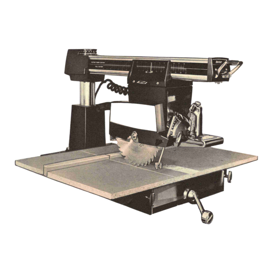
- Page 1 MODEL 10" RADIALARM SAW -I.', ptii " ..•. . :. . ® .. --. ,,'- . f ~\..,...
-
Page 2: Foreward
FOREWORD ThePowr-Kraft 10- Radial Arm Sawis a rugged- versatile power tool which IIgi e"'---- of excellent service, if properly used andcared for. You should thoroughly study this Owner's Guide beforeattempting to set upand use Spend a few minutes to become completely familiar with all the controls, their functio... -
Page 3: Table Of Contents
TABLE OF CONTENTS PAGE ......FOREWARD ••••••• SAFETY PRECAUTIONS PRODUCTIDENTIFICATION •••• CHAPTERI ASSEMBLY ANDADJUSTMENTS CHAPTERII · ·..Elevating Crank •••••• · Arm and Column ••••• · .. -
Page 4: Safety Precautions
SAFETY PRECAUTIONS Your Powr-Kraft Radial Arm Saw isdesigned with safety mind; you canrely and have confidence however, you must follow basic safety rules as with Remove Adjusting Keys andWrenches. Form habit of checking to seethat keys and adjusting wrenches are removed from tool before turning it on. -
Page 5: Chapteri Productidentification
CHAPTER I PRODUCT IDENTIFICATION MITER SCALE POINTER CARRIAGE LOCK INDEX LOCK ~P.:--- YOKE LOCK ANTI-KICKBACK AUXILIARY SPINDLE (COVERED WITH ASSEMBLY (20,000 R.P.M.) PROTECTIVE CAP) MOTOR BRUSHES --';':-!~~ AUXILIARY SPINDLE (COVERED WITH (3,450 R.P.M.) PROTECTIVE CAP) BEVEL LOCK ELEVATING EL LOCK CARRIAGELOCK :ecurely locksmotor... - Page 6 « ARM LOCK ADJUSTING WHEEL 14------ CARRIAGE SWITCH KEY WITCHHOLDING BUTTON SCALE SWITCH KEY Thetworip scales show thedisace be Must be inserted and presseddown before trigger switch andtheblade. Thesea Ieonthe left si will operate. usedfor outboard ripping andtheone is usedfor inboard ripping.
-
Page 7: Chapterii Assembly Andadjustments
(HAPTER I I ASSEMBLY AND ADJUSTMENT The following tools are required to assemble andad- just this saw: Includedwithsaw 1/4- AllenWrench 3/32- AllenWrench 3/4-, 1- Open End Wrench 5/8-,3/4-, 15/16- Open End Wrench 1/8- AllenWrench 5/64- AllenWrench Other toolsrequired: Screwdriver Phillips Screwdriver 1/2- Open End Wrench 9/16-... - Page 8 STEP4 INSTALLING MOTOR CARRIAGE ASSEMBLY ON ARM 1. Removearmindex (liT- shaped)handlefrom front of armbyremoving thephillips headscrewin center of thehandle. Fig. 6. Place the stirrup shapedarmlock handlein down position. Removethetwo phillips head screws from the end cap andremovetheend cap. CAUTION: While endcapis removed, donot movethe arm lockadjusting...
-
Page 9: Tableclampandelevating Bracket
TRACK TRACK MOVEMENTO~BEARING AS ECCENTRICSCREW IS ADJUSTED. FIG. FIG. STEP6 TABLE CLAMP AND ELEVATING BRACKET Attach table clamp andleveling bracket assemblies to frame usinghexbolts, flat washers andlockwashers as showninFig. DO NOT TIGHTEN THE BOL TS. STEP TABLE ASSEMBLY Assemble large table board toleveling brackets. - Page 10 STEP8 SIDE MOVEMENT OFARM-ELEVAT ING CRANK TENSION LOCK Move sawto rear of arm next to thecolumn. ADJUSTING 2. Setthearm at 0degrees onthemitre scale, making L--..-::•• iII!.r WHEEL certain thecolumn isseatedin thedetent. Tighten thearm(brake) lock. Thebrakeactionshouldfeel tight and secure whereas you must pushon the handlesolidly with thepalm of thehand.
-
Page 11: Assembling Theblade
8. Pull thesaw back andforth on the arm checking theclearance betweenthetableand the sawspindle. Usethetwo adjusting screws inthe right sideof the tableto adjust clearance. Loosenscrewsto increase clearance. Tightenscrews to reduceclearance. 9. Without changingthesettingof theelevating crank, release armlockandmovethe arm tothe 45°left position. 10. -
Page 12: Squaringthesaw Bladeto Thefence
SAW BLADES-APPLICATION CombinationBlade Amajor andoftenoverlooked causeof poor cutting is theblade. Makesurethat thesaw bladeissharp. Adull blade is a major causeof sawsnot cuttingproperly. Indications of dullness areroundedtips on theteethand theaccumulations of hardgum on theblade. Saw blades PlywoodBlade in this condition haveinsufficient set in the teethfor proper clearance and cut poorly. - Page 13 7. Move arm unti Ithe saw bladetouchesthe carpenter's square in all positions asthemotor ismovedback and forth onthe arm. 8. Hold arm steady and tighten bolts. 9. Replacehoodand pointer. 10. Adjust dial by turning so that pointer linesup with Degreeon scale. Once adjustedslight misallign- ment of thepointer...
- Page 14 c. Release bevel locking clamp andlift motor housing until bladeis parallel thesquare. Apply pressure to thelower part of saw blade with thumb until thereisabout 1/32- clearance betweenthesquareandthelower edgeof the blade. (Thiscompensatesfor motor movement when tightening screws.) Tighten three adjusting screws. d.
- Page 15 STEP14ASSEMBLING CARRIAGE COVERS Next thecarriage coversareassembled. Slideapointer (CC)over thecenter sectionof eachcover from the back so thepointer showsin cover window. Placespring (CD) andtrack wipers (CE) (felt) in eachend of cover. Attach carriage covers to carriage. Insert track lock pin (CV) intocarriage lock(CW) and thread carriage...
- Page 16 • ADJUSTMENT OFRIP SCALE OUTRIPFROM CENTER OUTRIP from center of table fence (Position 1) with fencepositionedasshown. OUTRIP FROM CENTER Rotate theyokesothat thebladefaces awayfrom the column. Movecarriage towardthecolumnuntil the blade touchesfront of fence.Adjust indicator on left sideof arm to zero positionat thetop of scale.
-
Page 17: Chapteriii Preparation Oftable
III PREPARATION OFTABLE CHAPTER Operation of thesaw requires that thebladeextendinto the table during most cutting operations. The table, therefore, must becut prior to use. Certain basiccuts canbe madein thetable. AFTERcompleting the adjustmentspreviously described. The basic cuts are: CROSS CUT, RIGHT ANDLEFT MITER and RIPPING. -
Page 18: Chapteriv Operatinginstructions
CHAPTER IV OPERATING INSTRUCTIONS OPERATING INSTRUCTIONS It is most important totakethetimeto becomecompletely familiar with all of thecontrols, their functionand operation of yournew radial arm saw. Makesure aII theassembly andadjustment instructions havebeen followedand completed beforeoperating thesaw. Becauseof theversatility of this radial arm saw, you shouldget into thepractice of planning your work in advancebeforeoperating thesaw. -
Page 19: Cross Cutting (9Qd Cut Off)
CAUTION: ALWAYS DISCONNECT SAWFROM POWER SOURCE BEFORE MAKING ADJUSTMENTS. CROSSCUTTING OR 9(Y CUTOFF (SAWING ACROSS THEWOOD GRAIN) Position theyokeindexin thecarriage so that theblade is at right angles tothefence. Tighten the yokelock. Set the armat 0degrees onthe miter scale, making certain the column is seatedin the detent. -
Page 20: Mitering
CAUTION: ALWAYS DISCONNECT SAW FROM POWERSOURCE BEFORE MAKING ADJUSTMENTS. ~B=~-ii_:7".Ii~~ : .-.;:::--: MITER ING Mitering is performed in the same manner as a90 degree cut off. The saw should bepushedto its rear stop. Release arm lock and pusharmtothedesired angle, thenretighten lock. -
Page 21: Molding Cutter Heads
ACCESSORIES DADOING TheDadobladeis put on theregular spindle. It is important that thedado bladebeassembledwiththe inner chippers positionedbetweensidebladeteethasmuchas possible in a balancedarrangement. Theupper guardshouldbe onwhileusingthe Dado blade. Thewidth of thedadoisdetermined by thenumber width of thesideblades and chippers assembledon the spindle. Thedepthof thedadois obtainedby adjusting theheight of the arm withrespect tothe work,... -
Page 22: Auxiliary Spindles
...•.." Jt> "-,-'.". ',:' ;.£ ..•.. ·· ...•.. ·.•.·.·.··.·· .• ACCESSORIES CONT'D. .• '-,' 'Y:·::., ib:~~ ROUTERBITS AUXILIARY SPINDLES This saw is equippedwith two auxiliary spindles. They SHAPING ROUTING 3,450 20,000 operate at RPM to give maximum flexibility with attachments. Speedsanddirection rotation are shownon the spind Ieplate. -
Page 23: Chapter Vmaintenanceandservice
CHAPTER VMAINTENANCEANDSERVICE TROUBLE CHART Use this chart for assistance to determine possible causeand correction of anyproblemyoumayexperience in operating your radial arm saw. CORRECTION PROBLEM POSSIBLECAUSE tension set screwas outlined Adjust Bevel Index doesnot hold TensionScrew notholding insection titled, "Bevel Angle Adjust- or islight ment"... - Page 24 POSSIBLECAUSE CORRECTION PROBLEM Column plugis not tight Adjust columnplug cisoutlined in section Arm has play when locked in position against column titled, ·SideMovement of Arm - Elevat- ing Crank Tens ion"on page10. Columnplug not adjusted Elevating HandleTight Adjust column plugasoutlined in see- properly tion titled,...
- Page 25 PROBLEM POSSIBLECAUSE CORRECTION Saw doesnot cut straight Saw not operatedproper- Refer to OperatingInstructions on page cutoff (Conf'd.) Refer tosectiontitled, "SideMovement Columntubeplug (AE)not of Arm" on page1O. engagedproper Saw base must be firm Iy mounted not mountedproperIy solidbase. Refer to "SquaringtheTable", on page Tablenot square...
- Page 26 ARM,COLUMNAND BASEASSEMBLY \.J~----_~_'r rr_'r AY AX --~~ 01/':...
- Page 27 DBASE ASSEMBLY ARM,COLU Ref. Ltr. Part Description 22-00764 Screw 17-00074 Split 21-03,892 Name!> ece 06-0l024-BMW Ce.. Screw, 5/8", Phillips Fi1lister Head 22-0P°J.3 05-00Sl3-POL Knob s-oi-oi.sss ::ee: Brake. 01-01429 Screw, .;;;;. -2..':' 3/8", Phillips Fi11ister Head 22-/00279 Stee "'C.S~ 1¥-00242 1< 27 00096 Compressi ?=;~...
- Page 28 YOKEASSEMBLY '" (;i:P...
- Page 29 YOKE ASSE Part ESCRIPTION X1/2-, Screw, #10-32 ~-2ri Phillips Oval Head Carriagn Cov.er (Le=t Hand) Pointer Spring Track Wiper Machine Screw, Specia Hex Nut, 5/16-18 17/64" Pivot Bolt Lock Washer Track Bearing Flat Washer Dowel Yoke Lock Screw, #10-32 m~-2A _/2D, Phillips Pan Head...
- Page 30 MOTORASSEMBLY TOOLS INCLUDED PARTNO. TOOL...
- Page 31 SSEMBlY Ref. Ltr. DESCRIPTION 06-00807 06-00808 14-00057 14-00056 14-00058 ==-=--..,.. 22-00481 1/4" 11-00162-3 1l-0009~ 22-00594 PhillipsPanHead 43-00449 28-00006 22-0012 SlottedBindingHead 2l-038~ 08-00_- 28-0 01-0 43':" 28-0 S-07-0 & 10-00067 one 10-00068 :;--c.:i SlottedFlatHead one 10-00022 Ball Bearings) SlottedFlatHead PhillipsPanHead PnillipsPanHead...
-
Page 32: Maintenance
MAINTENANCE LUBRICATION Thebearings andgears of this saw areproperly lubricated at thefactory. After extended useoldgrease shouldbeflushed outand refilled. isrecommendedthat thisbe doneby aqualified service man. The elevating shaft andgear shouldbelubricated periodically by coating thegearswith agood grade of grease. NOTE: Thearm track must not belubricated.
Need help?
Do you have a question about the TPC2610C and is the answer not in the manual?
Questions and answers