
Subscribe to Our Youtube Channel
Related Manuals for Daitsu FMCD*ECM series


Summary of Contents for Daitsu FMCD*ECM series
- Page 1 ECOELEGANT SERIES INSTALLATION OPERATION AND SERVICE MANUAL FMCD~ECM SERIES ...
- Page 2 Page 2 of 62 INVESTING IN QUALITY, RELIABILITY & PERFORMANCE. ISO 9001 QUALITY World Leading Design and Technology Every product is manufactured to meet Equipped with the latest CAD/CAM computer aided the stringent requirements of the design and manufacturing technology, our factories in internationally recognized ISO 9001 China and Thailand produce over 2,000,000 air standard for quality assurance in design, conditioning ...
-
Page 3: Table Of Contents
Page 3 of 62 Table of Content MODEL CODE NOMENCLATURE ............................ 5 A. TECHNICAL DATA .............................. 6 A.1. ..............................6 ENERAL ESCRIPTION A.2. ..............................7 ENERAL PECIFICATION A.2.1. FMCD–V–EC Series 3‐Speed Specifications ......................7 A.3. ..................................9 OIL A.3.1. 2‐Pipe Systems ..............................9 A.4. ............................... 10 IMENSIONAL ... - Page 4 Page 4 of 62 D.1. ............................ 52 EMOTE ONTROL ANDSET D.2. ................................. 53 IRED ALL D.2.1. Wall Pad Display ............................. 53 D.2.2. Wall Pad Operation Guidelines ........................ 54 D.2.3. EC Unit RPM Setting ............................ 57 E. SENSOR RESISTANCE R‐T CONVERSION TABLE ...................... 58 F. MODULE LAYOUT .............................. 60 G. TROUBLESHOOTING GUIDE ............................. 61 SK2014‐SON‐002‐TechMnl‐FMCD‐003...
-
Page 5: Model Code Nomenclature
Page 5 of 62 Model Code Nomenclature FMCD ‐ 06 ‐ V S ‐ ECM ECM EC Motor Configuration Complete function onboard PCB with S integrated group control functionality Limited function onboard PCB with drain‐ W pump, louver and zone control functionality V 2‐Pipe System ... -
Page 6: Technical Data
Page 6 of 62 Technical Data A.1. General Description This High‐Wall Unit is designed to meet and exceed demanding requirements for efficiency, quiet operation and appearance. The sleek profile and elegantly styled cabinet complements any interior design theme, while the microprocessor assures accurate environmental control. ... -
Page 7: General Specification
Page 7 of 62 A.2. General Specification A.2.1. FMCD–V–EC Series 3‐Speed Specifications Product range: FMCD‐ECM Hydronic High Wall with EC Motor FMCD‐V~‐ECM Hydronic High Wall 2‐pipe with EC Motor FMCD‐[Size]‐V~‐ECM 04 06 12 15 Configuration 2‐pipe Number Of Fan Blowers Single 230/1/50 Power Supply (V/Ph/Hz) 220/1/60 ~S: Complete function onboard PCB with integrated group control functionality, incl. 1 pc return air sensor and 2 pcs temperature sensors. Operation Control ~W: Limited function onboard PCB with drain‐pump, louver and zone control functionality, incl. 1 pc coil temperature sensor. H 370 500 500 645 Total Air Flow ... - Page 8 Page 8 of 62 Product range: FMCD‐ECM Hydronic High Wall with EC Motor FMCD‐[Size]‐V~‐ECM 18 20 24 Configuration 2‐pipe Number Of Fan Blowers Single 230/1/50 Power Supply (V/Ph/Hz) 220/1/60 ~S: Complete function onboard PCB with integrated group control functionality, incl. 1 pc return air sensor and 2 pcs temperature sensors. Operation Control ~W: Limited function onboard PCB with drain‐pump, louver and zone control functionality, incl. 1 pc coil temperature sensor. H 788 980 1240 Total Air Flow M /hr 740 760 760 L 570 600 600 ...
-
Page 9: Coil Data
Page 9 of 62 A.3. Coil Data A.3.1. 2‐Pipe Systems Tube Fin Height Fin Length Model Fins per Inch No. of Rows No. of Copper No. of Circuits Diameter (mm.) (mm.) (mm) FMCD‐04 230 680 2 8 2 7 FMCD‐06 230 680 2 14 3 7 FMCD‐12 230 680 2 22 ... -
Page 10: Dimensional Drawings
Page 10 of 62 A.4. Dimensional Drawings Dimensional drawing for FMCD‐04/06/12/15/18‐ECM (All dimensions shown in mm) ... - Page 11 Page 11 of 62 Dimensional drawing for FMCD‐20/24‐ECM (All dimensions shown in mm) ...
- Page 12 Page 12 of 62 A.5. Valve Information A.5.1. 2‐Way Valve Body Valve Dimensions (mm) DN A B C D 52 47 19.5 63 D15 (G1/2”) A.5.2. 3‐Way Valve Body Valve Dimensions (mm) DN ...
-
Page 13: Service And Installation
Page 13 of 62 Service and Installation B.1. Installation of High‐Wall Unit B.1.1. Selecting a Location Select the location for the High‐wall unit with the following considerations in mind: The front of the air inlet and outlet should be clear of any obstructions. The air should flow freely. The wall where the unit is to be mounted should be solid/firm enough not to resonate and produce noise. The location should allow easy access to install the connecting water pipes, and be where drainage can be easily achieved. Ensure the clearance around the fan coil unit conforms to the following drawing. From the floor the height of the unit should be above eye level. Avoid installing the unit in direct sunlight. Higher than eye level * Required clearance for maintenance and servicing is as shown above. ** All dimensions shown in mm. The signal receiver on the unit must be kept away from any high frequency emission source. Keep the unit away from fluorescent lamps, which may affect the control system. To avoid electromagnetic control system interference, ensure control wires are installed separately from 220‐240 VAC power wires. 10. Where electromagnetic waves are present, use shielded sensor cables. 11. Install a noise filter if the power supply creates any disruptive noises. SK2014‐SON‐002‐TechMnl‐FMCD‐003... -
Page 14: Mounting Plate Dimensions
Page 14 of 62 B.1.2. Mounting Plate Dimensions FMCD‐04/06/12/15/18 –ECM FMCD‐20/24/30 –ECM (All dimensions shown in mm) SK2014‐SON‐002‐TechMnl‐FMCD‐003... -
Page 15: Installing The Mounting Plate
Page 15 of 62 B.1.3. Installing the Mounting Plate 1. Select the structural position (e.g. a pillar or lintel) on the wall. 2. Then temporarily fasten the mounting plate on the wall with a steel nail. 3. Mount the mounting plate horizontally as shown in the above figure or by means of gradiometer. Failure to follow this may cause water to drip indoors and create additional noise. 4. Fix the mounting plate by means of expansion screws or tapping screws. B.1.4. Drilling the Condensate Drainage Hole 1. Ensure that the hole for condensate drainage is correctly positioned. The height should be lower than the bottom edge of the indoor unit. 2. Drill a 65mm diameter hole with a descending slope. 3. Seal it off with putty after installation. SK2014‐SON‐002‐TechMnl‐FMCD‐003... -
Page 16: Installing The Hydronic Unit
Page 16 of 62 B.1.5. Installing the Hydronic Unit Pass the piping through the hole in the wall and hook the indoor unit on the mounting plate by the upper hooks. Move the body of the unit from side to verify if it is securely fixed. While pushing the unit toward the wall, lift it slightly from beneath to hook it up on the mounting plate by the lower hooks. Make sure the unit firmly rests on the hooks of the mounting plate. B.1.6. Drainage Piping Works 1. Install the drain hose so that it slopes downward slightly for free drainage. Avoid installing it as shown in the below illustrations marked with an “X”. 2. Put water in the drain pan and make sure that the water drains outdoors. 3. If the flexible drain hose provided with the indoor unit is not long enough, please extend it by joining it to an extension hose (not provided). Be sure to insulate the connecting part of the extension drain hose with a shield pipe as shown. If the attached drain hose passes through an indoor area, insulate it with heat insulation material. SK2014‐SON‐002‐TechMnl‐FMCD‐003... -
Page 17: Unit Maintenances And Preparations
Page 17 of 62 B.2. Unit Maintenances and Preparations B.2.1. Opening and Closing Of Lift‐Up Grille Cover Close the grille cover by pressing down at the Open the grille cover by lifting from the positions indicated by the arrows. bottom position indicated by the arrows B.2.2. Removing Front Cover Assembly 1. Set the horizontal louver to the horizontal position. 2. Remove the screw caps below the louver, and then remove the mounting screws. 3. Open the lift‐up grille cover by grasping the panel at both sides as shown above. 4. Remove the remaining screws located in the center of the unit/of the front cover. 5. Grasp the lower part of the front cover and pull the entire assembly out and up towards you. SK2014‐SON‐002‐TechMnl‐FMCD‐003... -
Page 18: Air Purging
Page 18 of 62 B.2.3. Air Purging 1. After connecting the water inlet and outlet pipes to the main supply lines turn on the main breaker and operate the unit in COOLING mode. 2. Open the water inlet valve and flood the coil. 3. Check all connections for water leakage. If no leak is found open the water purge/air vent valve with an open end wrench and support the unit by hand. Then purge the air trapped inside the coil. When performing this activity, take care not to touch the electrical parts. 4. Close the water purge/air vent valve when no bubbles appear. 5. Open the water outlet valve. B.2.4. Wiring Connections Unit components are wired to the terminal block of the indoor unit. Wiring can be accessed from the terminal block inside the control box. ... -
Page 19: Pipe Connections With Valve
Page 19 of 62 B.3. Pipe Connections with Valve Pre‐assembly ½” gasket Coil connector Flexible copper Valve body with actuator Complete Assembly SK2014‐SON‐002‐TechMnl‐FMCD‐003... -
Page 20: Control Specifications
Page 20 of 62 Control Specifications C.1. SK‐NCFMCD‐001 Complete function FCU Controller Used in all High‐Wall [V] ~S unit configurations. Complete function integrated controller, compatible with IR handset controller, wired wall‐pad, serial networking for master‐slave and MODBUS applications. C.1.1. Abbreviations Ts = Setting temperature AUX1 = Hot water free contact Tr = Room air temperature AUX2 = Chilled water free contact Ti1 = Chilled water coil temperature MTV1 = Chilled Motorized valve Ti2 = Hot water coil temperature MTV2 = Hot Motorized valve C.1.2. Definition of Input/Output I/O ... -
Page 21: Wiring Diagram Sk-Ncfmcd-001
Page 21 of 62 C.1.3. Wiring Diagram SK‐NCFMCD‐001 SK2014‐SON‐002‐TechMnl‐FMCD‐003... -
Page 22: Configuration Settings
Page 22 of 62 C.1.4. Configuration Settings There are 2 DIP switches set on the PCB: a) DIPA‐S1 (8 positions) SW1 – SW6: used for master‐slave / BMS network address. SW7 – SW8: used for operating mode configuration. b) DIPB‐S2 (6 positions) SW1: Occupancy / economy mode selection. SW2: 2‐pipe / 4‐pipe configuration selection. SW3: Thermoelectric valve configuration selection (2‐pipe system only). SW4: Pre‐heat protection temperature selection. SW5 – SW6: brushless DC fan motor configuration. 1. Default DIP Switch Settings: Unit Configuration WITHOUT Valve Figure 1 ... - Page 23 Page 23 of 62 SW2 System setting 0 2‐pipes system 1 4‐pipes system SW4 Preheat setting 1 28°C 0 36°C 4. Motorized Fan Speed Settings for Different Models: Speed (RPM) Unit Model S3 SW5 SW6 Low Medium High FMCD‐04 500 0 FMCD‐06 600 1 FMCD‐12 600 0 FMCD‐15 700 1150 1 ...
-
Page 24: Control Logics For 2-Pipe System
Page 24 of 62 C.1.5. Control Logics for 2‐Pipe System C.1.5.1. With Thermoelectric Valve Configuration COOL MODE a) MTV2, AUX1 and electric heater are always off. b) If Tr ≥ Ts + 1ºC (or + 4ºC if economy contact is activated), then cool operation is activated and MTV1 and AUX2 are turned on. Indoor fan runs at set speed. c) If Tr < Ts, then cool operation is terminated and MTV1 and AUX2 are turned off. Indoor fan runs at set speed. d) The range of Ts is 16 ‐ 30ºC e) Indoor fan speed can be adjusted to low, medium, high and auto. f) When turned on, MTV1 requires 30 seconds before it is fully open. g) When turned off, MTV1 requires 120 seconds before it is fully closed. h) When the unit is turned off, the indoor fan will shut down after 5 seconds. LOW TEMPERATURE PROTECTION OF INDOOR COIL a) If Ti1 ≤ 2 ºC for 2 minutes, then MTV1 and AUX2 are turned off. If indoor fan is set for low speed, then it will ... - Page 25 Page 25 of 62 With Electrical Heater as Primary Heat Source a) MTV1, MTV2 , and AUX2 are always off. b) If Ti2 ≤ 30ºC (or Ti2 is damaged or not connected), 1) If Tr ≤ Ts﹣1ºC (or – 4ºC if economy contact is activated), then heat operation is activated and the electrical heater and AUX1 are turned on. Indoor fan runs at set speed. 2) If Tr > Ts, then heat operation is terminated and the electrical heater and AUX1 are turned off. Indoor fan runs at 200RPM. If Ti2 > 30ºC, MTV2 and AUX2 are off. 1) If Tr ≤ Ts﹣1ºC (or – 4ºC if economy contact is activated), then heat operation is activated and the electrical heater is turned off while MTV1 and AUX1 are turned on. Indoor fan runs at set speed. 2) If Tr > Ts, then heat operation is terminated and MTV1 and AUX1 are turned off. Indoor fan runs at 200RPM. ...
- Page 26 Page 26 of 62 DEHUMIDIFICATION MODE a) MTV2, AUX1 and heater are always off. b) If Tr ≥ 25ºC, then MTV1 and AUX2 will be ON for 3 minutes, and then OFF for 4 minutes. c) If 16ºC ≤ Tr < 25ºC, then MTV1 and AUX2 will be ON for 3 minutes, and then OFF for 6 minutes. d) If Tr < 16ºC, then MTV1 and AUX2 will be turned off for 4 minutes. e) At the end of the above dehumidification cycle, the system will decide the next dehumidification control option. Indoor fan will run at low speed throughout the dehumidification process. AUTOMODE Without Electric heater and With Electric Heater as Booster a) Every time the unit is turned on, MTV1 is on while AUX1, AUX2 and fan are off. MTV2 and the heater are always off. After 120 seconds, the subsequent operation mode is decided according to the following: ...
- Page 27 Page 27 of 62 FAN MODE a) Indoor fan runs at the set speed while heater, AUX1, AUX2, MTV1 and MTV2 are turned off. b) Indoor fan speed can be adjusted to low, medium and high. HEAT MODE Without electrical heater a) MTV1, MTV2, AUX2 and heater are always off. b) If Tr ≤ Ts ‐ 1ºC (or ‐ 4ºC if economy contact is activated), then heat operation is activated and AUX1 is turned on. Indoor fan runs at the set speed. c) If Tr > Ts, then heat operation is terminated and AUX1 is turned off. Indoor fan runs at 200rpm. d) The range of Ts is 16 ‐ 30ºC. e) Indoor fan speed can be adjusted to low, medium, high and auto. With electrical heater as booster a) MTV1, MTV2 and AUX2 are always off. b) If Tr ≤ Ts ‐ 1ºC (or ‐ 4ºC if economy contact is activated), then heat operation is activated and AUX1 is turned on. Indoor fan runs at the set speed. c) If Tr > Ts, then heat operation is terminated and AUX1 is turned off. Indoor fan runs at 200 rpm. d) If Ti1 < 40ºC, then the electrical heater is turned on. If 40ºC ≤ Ti1 < 45ºC, then the electrical heater maintains its original state. If Ti1 ≥ 45ºC, then the electrical heater is turned off. e) The range of Ts is 16 ‐ 30ºC. f) Indoor fan speed can be adjusted to low, medium, high and auto. ...
-
Page 28: Control Logics For 4-Pipe System
Page 28 of 62 POST‐HEAT With and Without Electrical Heater a) AUX1 is turned off. Electrical heater is turned off. b) Indoor fan will shut down after the unit has been turned off for 20 seconds. LOW TEMPERATURE PROTECTION OF INDOOR COIL a) If Ti1 ≤ 2ºC for 2 minutes, then AUX2 is turned off. If indoor fan runs at low speed, then it will run at medium speed. If indoor fan runs at medium or high speed, then it will run at set speed. b) If Ti1 ≥ 5ºC for 2 minutes, then AUX2 is turned on. Indoor fan runs at set speed. OVER‐HEAT PROTECTION OF INDOOR COIL a) If Ti1 ≥ 75ºC, then AUX1 is turned off. Indoor fan remains on and runs at high speed. b) If Ti1 < 70ºC, then AUX1 is turned on. Indoor fan remains and runs at set speed. c) If the indoor coil temperature sensor is damaged, then the protection mode will be overridden and the unit will work according to the pre‐heat and post‐heat program. DEHUMIDIFICATION MODE a) MTV1, MTV2, AUX1 and heater are always off. b) If Tr ≥ 25ºC, then the indoor fan and AUX2 will be turned on for 3 minutes, and then off for 4 minutes. c) If 16ºC ≤ Tr < 25ºC, then the indoor fan and AUX2 will be turned on for 3 minutes, and then off for 6 minutes. d) If Tr < 16ºC, then the indoor fan and AUX2 will be turned off for 4 minutes. e) At the end of the above dehumidification cycle, the system will decide the next dehumidification control option. Indoor fan will run at low speed throughout the ... - Page 29 Page 29 of 62 HEAT MODE Without Electrical Heater a) MTV1, AUX2 and electric heater are always off. b) If Tr ≤ Ts ‐ 1ºC (or ‐ 4ºC if economy contact is activated), then heat operation is activated and MTV2 and AUX1 are turned on. Indoor fan runs at the set speed. c) If Tr > Ts, then heat operation is terminated and MTV2 and AUX1 are turned off. Indoor fan runs at 200RPM. d) The range of Ts is 16 ‐ 30ºC. e) Indoor fan speed can be adjusted to low, medium, high and auto. f) When turned on, MTV2 requires 30 seconds before it is fully open. g) When turned off, MTV2 requires120 seconds before it is fully closed. With Electrical Heater as Booster a) MTV1 and AUX2 are always off. b) If Tr ≤ Ts ‐ 1ºC (or – 4ºC if economy contact is activated), then heat operation is activated and MTV2 and AUX1 are turned on. Indoor fan runs at the set speed. c) If Tr > Ts, then heat operation is terminated and MTV2 and AUX1 are turned off. Indoor fan runs at 200RPM. d) If Ti1 < 40ºC, then the electrical heater is turned on. If 40ºC ≤ Ti1 < 45ºC, then the electrical heater maintain its original state. If Ti1 ≥ 45ºC, then the electrical heater is turned off. e) The range of Ts is 16 ‐ 30ºC. f) Indoor fan speed can be adjusted to low, medium, high and auto. g) When turned on, MTV2 requires 30 seconds before it is fully open. ...
- Page 30 Page 30 of 62 LOW TEMPERATURE PROTECTION OF INDOOR COIL a) If Ti1 ≤ 2ºC for 2 minutes, then MTV1 and AUX2 are turned off. If indoor fan is set for low speed, then it will run at medium speed. If it is set at medium or high speed, then it will keep running at the same speed. b) If Ti1 ≥ 5ºC for 2 minutes, then MTV1 and AUX2 are turned on. Indoor fan runs at set speed. OVER HEAT PROTECTION OF INDOOR COIL a) If Ti2 ≥ 75ºC, then MTV2 and AUX1 are turned off. Indoor fan remains on and runs at high speed. b) If Ti2 < 70ºC, then MTV2 and AUX1 are turned on. Indoor fan remains on and runs at set speed. c) If the indoor coil temperature sensor is damaged, then the protection mode will be overridden and the unit will work according to the pre‐heat and post‐heat set times. DEHUMIDIFICATION MODE a) MTV2, AUX1 and heater are always off. b) If Tr ≥ 25ºC, then MTV1 and AUX2 will be turned on for 3 minutes, and then off for 4 minutes. c) If 16ºC ≤ Tr < 25ºC, then MTV1 and AUX2 will be turned on for 3 minutes, and then off for 6 minutes. d) If Tr <16ºC, then MTV1 and AUX2 will be turned off for 4 minutes. e) At the end of the above dehumidification cycle, the system will decide the next dehumidification control option. Indoor fan will run at low speed throughout the dehumidification process. AUTO‐MODE a) If the current running mode is AUTO COOL mode, it will change over to AUTO HEAT mode upon satisfying all the conditions below: ...
-
Page 31: Sleep Mode
Page 31 of 62 C.1.7. Sleep Mode a) SLEEP mode can only be set when the unit is in COOL or HEAT mode. b) In COOL mode, after SLEEP mode is set, the indoor fan will run at low speed and Ts will increase by 2ºC over 2 hours. c) In HEAT mode, after SLEEP mode is set, the indoor fan will run at set speed and Ts will decrease by 2ºC over 2 hours. d) Changing of operation mode will cancel SLEEP mode. The COOL mode SLEEP profile is: Set temperature ... -
Page 32: Auto Fan Speed
Page 32 of 62 C.1.8. Auto Fan Speed In COOL mode, the fan speed cannot change until it has run for more than 30 seconds. Fan speed is regulated according to the profile below. Tr High Ts+3C High Medium Ts+2C Low Medium Ts+1C Low Low Ts In HEAT mode, the fan speed cannot change until it has run for more than 30 seconds. Tr Ts Low ... -
Page 33: Louver
Page 33 of 62 C.1.9. Louver For remote handset with Control Box – I (Integrated Full Control Version) Whenever the indoor fan is running, the louver can swing or stop at the desired position. Louver angle: 0~100º, opens clockwise with widest angle at 100º. Swing angle: 35~100º, opens clockwise to 68º. Below are the 4 fixed positions which can be set from wireless LCD handset. Position Angle 1 35º 2 57º 3 83º 4 100º For wired wall pad with Control Box – I (Integrated Full Control Version) Louver angle: 0~100º, opens clockwise with angle at 100º. Swing angle: 35~100º, opens clockwise to 68º. User may stop louver at any desired position between 35~100º. C.1.10. Buzzer If a command is received by the air conditioner, the master unit will respond with 2 beeps for each setting, while the slave unit will respond with 1 beep. C.1.11. Auto Restart The system uses non‐volatile memory to save the present operation parameters when system is turned off or in case of system failure or cessation of power supply. Operation parameters when using a handset are Mode, Set Temperature, Swing, and Fan Speed. When using a wall pad the parameters are Mode, Set Temperature, Swing, and Fan Speed, as well as the 7‐day ON/OFF Timer program. When power supply resumes or the system ... -
Page 34: C.1.12. Operation Of Control Panel On High-Wall Unit
Page 34 of 62 C.1.12. Operation Of Control Panel On High‐Wall Unit C.1.12.1. On/Off Switch a) This is a tactile switch to select Cool→Heat→Off opera on mode. b) In COOL mode, the set temperature of the system is 24ºC with auto fan speed and swing. There are no timer and sleep modes. c) In HEAT mode, the set temperature of the system is 24ºC with auto fan speed and swing. There are no timer and sleep modes. d) Master unit that does not use a wall pad will globally broadcast. Note: When button pressing is effective, the master unit buzzer will beep twice and the slave unit will beep once. C.1.12.2. Electric Heater Safety Switch a) Before the electrical heater is turned on, the EH safety switch must be closed. If this contact is opened continuously ≥ 1 second, the heater will be turned off immediately and report an error. Once the contact is ... -
Page 35: Led Lights
Page 35 of 62 C.2. LED Lights For all units Power / Operation LED light (both green) Unit on Operation LED On, Power LED Off Unit in standby Power LED On, Operation LED Off SK2014‐SON‐002‐TechMnl‐FMCD‐003... -
Page 36: Led Indication And Error Description
Page 36 of 62 C.2.1. LED Indication and Error Description For all units ‐ Operation LED light (Green) Error Description Blink Reason Remedy Only for unit with EH. 1. Change fan speed to high. Green LED blinks 1 times, Electrical heater failure EH safety switch is 2. Replace the damaged EH safety stops for 3s open. switch. 1. Check if Ti2 plug is connected or not. Green LED blinks 2 times, Ti2 sensor unplugged or Indoor coil sensor 2 failure 2. Check if sensor’s resistance is correct stops for 3s damaged. or not. 1. Check if Tr plug is connected or not. Green LED blinks 3 times, Room sensor unplugged Return air sensor failure 2. Check if sensor’s resistance is correct stops for 3s ... -
Page 37: Led Indication On Master/Slave Connection
Page 37 of 62 C.2.2. LED Indication on Master/Slave Connection The error message indicating the defect status of all slave units will be shown in LED lights on the master unit. Master unit Protection LED light (Red) Unit No. Blink Remedy Unit 2 failure RED LED blinks 2 times, stops for 3s Check unit 2 communication plug and fix it Unit 3 failure RED LED blinks 3 times, stops for 3s Check unit 3 communication plug and fix it Unit 4 failure RED LED blinks 4 times, stops for 3s Check unit 4 communication plug and fix it Unit 5 failure RED LED blinks 5 times, stops for 3s Check unit 5 communication plug and fix it Unit 6 failure RED LED blinks 6 times, stops for 3s Check unit 6 communication plug and fix it Unit 7 failure RED LED blinks 7 times, stops for 3s Check unit 7 communication plug and fix it Unit 8 failure RED LED blinks 8 times, stops for 3s Check unit 8 communication plug and fix it Unit 9 failure RED LED blinks 9 times, stops for 3s Check unit 9 communication plug and fix it Unit 10 failure RED LED blinks 10 times, stops for 3s Check unit 10 communication plug and fix it Unit 11 failure ... -
Page 38: Networking System
Page 38 of 62 C.3. Networking System C.3.1. Master‐Slave Network The control PCB can be set either as a master unit or slave unit. MASTER UNIT FUNCTION a) The master unit sends data regarding its setting to the slave unit. b) The master unit settings are unit ON/OFF, Mode, Fan Speed, Timer, Clock, Set Temperature, Swing Function, and Sleep Function for handset operation. The master unit settings are unit ON/OFF, Mode, Fan Speed, Timer, Clock, Set Temperature, Swing Function, and Sleep Function for wall pad operation. SLAVE UNIT FUNCTION a) The slave unit receives data regarding its settings from the master unit. b) The slave unit is allowed to change to a locally desired setting by local controller as long as there are no subsequent changes to the settings of the master unit. ... -
Page 39: C.3.2. Master - Slave Network Setup
Page 39 of 62 C.3.2. Master – Slave Network Setup 1) Disconnect the communication plug from the control box 2) Communication plug A, B, A, B is printed on the main PCB. When you connect the wires, please ensure connection of A to A and B to B. 3) Connection wire 3.1) If the total length of wire is more than 1000m, please use shielded wire in order to protect the signal transmission. 3.2) Complete wire connection First unit Middle unit Last unit SK2014‐SON‐002‐TechMnl‐FMCD‐003... - Page 40 Page 40 of 62 First unit Middle unit Last unit 3.3) Wire connection check 3.3.1) After the wire connection is completed, please check that the wire colours correspond. 3.3.2) Check the wire contact by using a multimeter. contact contact contact contact contact contact 3.3.3) Check 1 and 2, 3 and 4, 5 and 6 to be sure the connections are correct. 3.3.4) If the resistance between two wire contacts is too high, please check and reconnect the wire contacts. SK2014‐SON‐002‐TechMnl‐FMCD‐003...
- Page 41 Page 41 of 62 4) Reconnect the communication plug to the control box Using Remote Control Handset to Set Master Control Unit: a) Connect all the units PCBs according to the wire color and type of connector. b) Select the master unit by setting DIPA‐S1 SW6 to ON (=1) in the PCB. c) Ensure the DIPA‐S1 SW6 is set to OFF (=0) in the PCB on each slave unit. d) Switch on the units by connecting the main power supply. e) Using the handset set the operation parameters for the master unit which will automatically send the settings to the slave unit. f) Master unit will beep twice confirming receipt of commands while the slave unit will beep once. Using Wall pad to Set Master Control Unit: a) Connect all the units PCBs according to the wire color and type of connector. b) Select the master unit by setting DIPA‐S1 SW6 to ON (=1) in the PCB. c) Ensure the DIPA‐S1 SW6 is set to OFF (=0) in the PCB on each slave unit. d) Provide each slave unit with an addressable code by configuring SW1 – SW5 of DIPA‐S1 according to the DIP switch setting table. e) Switch on the units by connecting the main power supply. f) Using the wall pad set the operation parameters for the master unit which will send the setting to the slave units by Global‐control communication or Addressable communication methods. g) Master unit will beep twice confirming receipt of commands while the slave unit will beep once. MASTER‐SLAVE CONTROL ...
-
Page 42: Master - Slave Communication Method
Page 42 of 62 C.3.3. Master ‐ Slave Communication Method There are two modes for the master‐slave structure. Global Control communication The Master unit will broadcast the settings to all slave units. During normal operation, slave units can receive commands from its local wireless handset and wall pad control panel. Upon reception of master global commands, all slave unit settings will be replaced by the master settings. Addressable communication The Master controller must be the LCD wall pad. Slave unit parameters are set as usual. Upon receiving the control commands from a master, the addressed slave unit settings will be replaced by the master settings. ... -
Page 43: Unit Network Wiring Scheme
Page 43 of 62 C.3.4. Unit Network Wiring Scheme Wiring diagram for a master‐slave network connection SK2014‐SON‐002‐TechMnl‐FMCD‐003... -
Page 44: Sk-Ncfmcd-002 Limited Function Fcu Controller
Page 44 of 62 C.4. SK‐NCFMCD‐002 Limited function FCU Controller Used in all High‐wall [V] ~W unit configurations. Ti1 = Chilled water coil temperature (10K) C.4.1. Definition of Input/Output I/O Code 2‐Pipe Analogue Input Chilled water sensor AI1 Coil sensor Power input R1 230 Voltage input (NO). If any fan speed is selected, the unit is receiving power. If no fan speed is selected, the unit R 2 is not receiving power. R 3 Power supply to the PCB and all the loads connected to Phase ... -
Page 45: Wiring Diagram Sk-Ncfmcd-002
Page 45 of 62 C.4.2. Wiring Diagram SK‐NCFMCD‐002 SK2014‐SON‐002‐TechMnl‐FMCD‐003... -
Page 46: Onboard Configuration
Page 46 of 62 C.4.3. Onboard Configuration There is 1 DIP switch set on the PCB: DIPB (4 positions) SW1: configured for different modulating signal. SW2 – SW4: brushless DC fan motor configuration. Code State Description 0 PCB configured for 0~5VDC modulating signal input. SW1 1 PCB configured for 0~10VDC modulating signal input. MODEL SW2 SW3 SW4 Hi Med Low 0 0 0 700 600 500 ... -
Page 47: Led Indication
Page 47 of 62 C.4.5. LED Indication For all units Power / Operation LED light (both green) Unit on Operation LED On, Power LED Off Unit in standby Power LED On, Operation LED Off C.4.6. Error Description For all units ‐ Operation LED light (Green) Item Blink Reason Remedy 1. Check if Ti1 plug is connected or not. Indoor coil sensor 1 Green LED blinks 4 Ti1 sensor connection is 2. Check if sensor’s resistance is correct or failure times, stops for 3s unplugged or damaged. not. 1. Check if EC motor’s wires are connected. Green LED blinks 9 EC motor failure No EC motor feedback times, stops for 3s 2. Check the EC motor ... -
Page 48: Open Modbus Protocol
Page 48 of 62 C.5. Open Modbus protocol Transfer Mode: RTU, BAUD Rate: 9600bps, 8 data bit, 1 stop bit, None parity bit The communications require a delay of 80ms between reading an answer and sending the next command. All temperatures are equal to reading data*10 accuracy: 0.1 degree C. Supported Functions: Function Code Function Description 01(01H) Read Coils 02(02H) Read Discrete Inputs 03(03H) Read Holding Registers 04(04H) Read Input Registers 05(05H) Write Single Coil 06(06H) Write Single Register 15(0FH) Write Multiple Coils 16(10H) Write Multiple Registers 255(FFH) Extended Commands which are used to test unit Valid Error code table: Error code ... -
Page 49: Wired Wall Pad
Page 49 of 62 Coils table: Description Address Type* Remark Unit ON/OFF 100000 Sleep mode 100001 Louver swing 100002 Reserved 100003 Reserved 100004 Reserved 100005 Reserved 100006 Reserved 100007 Reserved 100008 Reserved 100009 Reserved 100010 Reserved 100011 Reserved 100012 Reserved 100013 Reserved 100014 ... - Page 50 Page 50 of 62 Holding Register table: Description Address Type* Remark Cooling mode = 01(H) Humidify mode = 02(H) Mode setting 300000 R/W Fan mode = 04(H) Heating mode = 08(H) Auto mode = 10(H) Low speed = 04(H) Medium speed = 02(H) Fan speed setting 300001 R/W High speed = 01(H) Auto fan speed = 07(H) Position 1 = 01(H) Position 2 = 02(H) Position 3 = 03(H) Louver swing setting 300002 R/W Position 4 = 04(H) Auto = 0F(H) Stop = 00(H) Setting temperature 300003 16~30 degree C (actual*10 format) Address setting 300004 Set by dip‐switch, reading only ...
- Page 51 Page 51 of 62 Input Register table: Description Address Type* Remark Dip switch 1 status 400000 R Dip switch 2 status 400001 R Room temperature sensor 400002 R Ti1 temperature sensor 400003 R Ti2 temperature sensor 400004 R Bit0 = Room temperature sensor error Bit1 = Ti1 temperature sensor error Bit2 = Ti2 temperature sensor error Bit3 = Float switch error Bit4 = Indoor coil low temperature protection Bit5 = Indoor coil over heat protection Bit6 = Reserved Bit7 = Electrical heater failure Error code 400005 R Bit8 = Motor1 Error Bit9 = Motor2 Error Bit10 = System parameters error Bit11 = Reserved ...
-
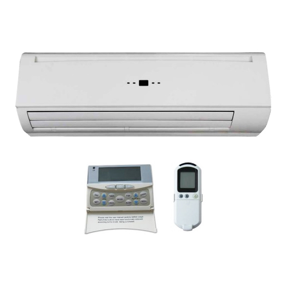
Page 52: D. User Interface
Page 52 of 62 User Interface D.1. Remote Control Handset Swing It is not available. Attention When unit with handset is the master unit, settings are automatically sent to the slave units; Auto Cool‐Heat operation will be applicable in 4‐pipe system only. “Swing” function is not applicable. SK2014‐SON‐002‐TechMnl‐FMCD‐003... -
Page 53: Wall Pad Display
Page 53 of 62 D.2. Wired Wall Pad D.2.1. Wall Pad Display ... -
Page 54: Wall Pad Operation Guidelines
Page 54 of 62 D.2.2. Wall Pad Operation Guidelines a) Clock display and setting System has an accurate internal real time clock used for time indication and timer ON/OFF function. Clock display area TIME indicates internal time clock which can be set by the or button. TIME b) Day display and setting The wall pad has a day display function which is used for day indication and timer ON/OFF function. Day display icon indicates current day. Press button to set day. c) Timer ON/OFF setting If the master unit is in global control mode and the ON/OFF timer setting is selected, the master unit will command the whole network to be on or off. Otherwise the ON/OFF timer affects the local unit only. The system supports individual ON/OFF timer settings for each day of the week. ... - Page 55 Page 55 of 62 display area will show “rEAd”. The OFF timer setting will be shown upon reading the data successfully. Press TIME or button to change the OFF timer setting of the slave unit. TIME TIMER Upon completion of changing timer settings for the selected day, press button again to exit timer programming mode. The settings will then upload to the selected slave unit. The next day of the week’s settings can be done only upon completion of sending data to the slave units. (Repeat steps 1~4 if setting is ...
- Page 56 Page 56 of 62 l) On/Off control Press to start or stop the unit. m) Networking Master ‐ Slave Control (only master unit wall pad can control other units on the network) Press button to enter into networking control mode. Unit’s display are blinking indicates the slave unit TIME under control. Press or to select the desired slave unit; Units that are off will be bypassed TIME automatically. Parameters that can be controlled are on/off, timer weekly program, set temperature, mode, ...
-
Page 57: Ec Unit Rpm Setting
Page 57 of 62 D.2.3. EC Unit RPM Setting 1) Turn OFF the unit. 2) Open wall pad’s back cover, where two DIP switches can be seen. 3) Turn the DIP switch 1 to “ON” position. 4) Wired wall pad LCD will display the following; This is the speed level setting. d0 means low speed d1 means medium speed d2 means high speed Press PARAMETER + / ‐ button to select speed This is the motor RPM setting. Press TEMP. + / ‐ button to increase the RPM setting by 10RPM step. 5) After selecting the RPM setting, turn the DIP switch 1 to the “OFF” position. The wired wall pad display will resume its normal appearance. SK2014‐SON‐002‐TechMnl‐FMCD‐003... -
Page 58: Sensor Resistance R-T Conversion Table
Page 58 of 62 Sensor Resistance R‐T Conversion Table Resistance: R (25°C) = 10KΩ±1% Beta Constant: B (25/ 85) = 528K±1% Rmin Rnom Rmax Rmin Rnom Rmax T T (KΩ) (KΩ) (KΩ) (KΩ) (KΩ) (KΩ) ‐30 174 182.7 191.8 26.11 26.9 27.71 ‐29 163.4 171.5 179.9 24.85 25.59 26.34 ‐28 153.6 ... - Page 59 Page 59 of 62 Rmin Rnom Rmax Rmin Rnom Rmax T T (KΩ) (KΩ) (KΩ) (KΩ) (KΩ) (KΩ) 38 5.614 5.759 5.907 1.417 1.474 1.532 39 5.387 5.53 5.673 1.37 1.426 1.482 40 5.172 5.31 5.451 1.326 1.379 1.434 41 ...
-
Page 60: Module Layout
Page 60 of 62 Module Layout SK‐DFPS‐HWC‐006: 220V / 230V Electrical heater kit for FMCD. Electrical heater SK2014‐SON‐002‐TechMnl‐FMCD‐003... -
Page 61: Troubleshooting Guide
Page 61 of 62 Troubleshooting Guide Symptoms Cause Remedy The fan coil does - Check for presence of No voltage not start up voltage Mains switch in the “OFF - Place in the “ON” position position Faulty room control - Check the room control - Check fan motor Faulty fan Insufficient output Filter clogged - Clean the filter Air flow obstructed - Remove obstacles - Check the room air sensor Room control regulation - Check the water source Incorrect water temperature - Check the air vent Air present ... - Page 62 Page 62 of 62 SK2014‐SON‐002‐TechMnl‐FMCD‐003...
Need help?
Do you have a question about the FMCD*ECM series and is the answer not in the manual?
Questions and answers