Table of Contents
Advertisement
Quick Links
Advertisement
Table of Contents

Related Manuals for EOS EMOTEC B6000

Summary of Contents for EOS EMOTEC B6000
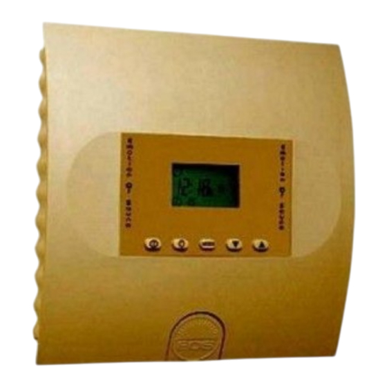
- Page 1 Installation and user guide EMOTEC B6000 IP x4 Druck Nr. 29342340en 43.06...
-
Page 2: Table Of Contents
Table of Contents General information concerning sauna bathing ............. 3 Scope of delivery ....................4 General safety precautions ................... 4 Assembly of the control unit ................. 4 Wall mounting .................... 4 Electrical connection .................... 6 Connecting the sauna heater ................6 Connecting the sauna lamp .................. -
Page 3: General Information Concerning Sauna Bathing
General information concerning sauna bathing Dear customer, Please note the variation in temperatures in the cabin while sauna bathing. The with purchase of this sauna control unit you hottest area is directly under the cabin opted for a superior quality, high-tech ceiling, whereas there is a steady electronic device which was developed and temperature gradient towards the floor of... -
Page 4: Scope Of Delivery
assembly instructions, especially when Package contents (subject to change) installing the temperature sensor. The Included with the control unit are: temperature above the oven is critical for temperature setting. 1. An heater-sensor board with overheat temperature can be held within operating shutoff protection, KTY-sensors with parameters and a minimal temperature sensor housing , two 3x25 mm... - Page 5 Illust . 3.2 Illust . 3.3 Illust. 1 3. Hang the control unit onto the 3 mm projecting screw. Insert the included 1. Remove the cover of the control unit. To rubber sleeves into the openings on the do this press the fastening tab inwards back side of the housing and lead the with a flat screwdriver and remove the electrical cable through these openings.
-
Page 6: Electrical Connection
Please note: If the sauna cabin is not Lead wire for cabin lighting equipped with electrical conduits, the Power supply lead wire electrical cables must be lead along the outside of the cabin, preferably in one of the recesses between the wood boards. Therefore, you have to mount the control unit farther away from the cabin wall, so you can lead the cables into the unit. -
Page 7: Connecting The Sauna Lamp
Mounting the oven sensor Connecting the sauna lamp 1. Mount the oven sensor in cabins up to The sauna lamp must be splashproof (by 2 x 2m according to Illust. 6 and 7, in larger Standard IPx4) and resistant to ambient cabins according to Illust. - Page 8 4. Attach the lines for the shutoff (white) and the temperature sensor (red) according to Illust. 10 to the sensor board. Then insert the sensor board into the housing. Sensor board Housing Illust. 10 5. After you are finished installing and have made sure the control unit is functioning properly, check the line for overheat shutoff protection for short circuits.
-
Page 9: Operation
Operation Button Functions Mode Operating switch Lamp Program Selection on - off on - off button buttons Illust. 11 Symbol description Time Heating (dry) Pre-selected time Ventilation function Heating time... -
Page 10: Unit Initialization
Unit initialization After checking all connections once more, connect the unit to the power supply by switching on the fuse and the main switch. On the display appears and the clock symbol begins to blink. After a short time (30 seconds) you can 12:00 start with programming. -
Page 11: Default Parameters
Default parameters Finnish sauna operation 20:03 After switching on the unit, the display alternates between the time of day and the remaining heating time. 05:58 Temperature indicator The temperature is displayed on the right- hand side of the display by a thermometer symbol. -
Page 12: Important Notes When Programming
If you wish to end your sauna bath Mode prematurely, press the button. The symbol on the display then disappears. Important notes when programming Every modification of the preset parameters must be confirmed by pressing the "MODE" button. If you do not press the "MODE" button, the unit will automatically default back to the previous parameters. -
Page 13: Changing The Default Temperature
Changing the default temperature Temperature setting By default the temperature for Finnish operation is set to 95°C. To change this parameter, press the "MODE" button. P1 then appears on the display in the programming area. Press the button repeatedly until P3 and the heating symbol appear on the display, and confirm this with the "MODE"... - Page 14 Using the selection buttons can now set heating time. Please consider, though, that the cabin needs 40-50 minutes for warming up, to create a pleasant climate in the cabin. For example, if you wish to take your sauna 17:10 bath at 6 p.m., then you should set the startup time to 5:10 p.m.
-
Page 15: Programming Current Time
Programming current time To reach this program level, press the "MODE" button and the button simul- taneously until F1 is displayed, as well as the clock symbol. You can change the time with function F1. Confirm with the "MODE" button and the previously set time begins to blink with the 20:03 clock symbol. -
Page 16: The Control Unit Switch
The control unit switch The control unit switch can be found on the Control unit switch top end of the unit. Using this switch, you can isolate the electronics from = unit the mains supply in case of a breakdown. switched Please note that operating the control unit switch returns all settings to the factory... -
Page 17: Technical Data
Technical data Rated voltage: 400 V 3 N 50 Hz AC Schaltleistung: max 9 kW resistive load (AC 1 operation) upgrade to 36 kW possible through connection to power control units Heating time shut-off: Display: LCD, backlit Protection type: IPx4 in accordance with DIN 40050 (German Standards Institution), splashproofing Control range, sauna operation: 30 to 115°C Sensor system:... -
Page 18: Wiring Diagram
Wiring diagram... -
Page 19: Terms Of Warranty
Service address: Guarantee EOS-Werke Günther GmbH The guarantee is taken over according to the legal D-35759 Driedorf, Germany regulations at present. Tel. +49 (0) 27 75 8 22 40 Fax +49 (0) 27 75 8 24 55 e-mail: servicecenter@eos-werke.de Manufacturer’s warrenty Internet: www.eos-werke.de...
Need help?
Do you have a question about the EMOTEC B6000 and is the answer not in the manual?
Questions and answers