
Related Manuals for Global Right Flyer 40T Mk.II

Summary of Contents for Global Right Flyer 40T Mk.II
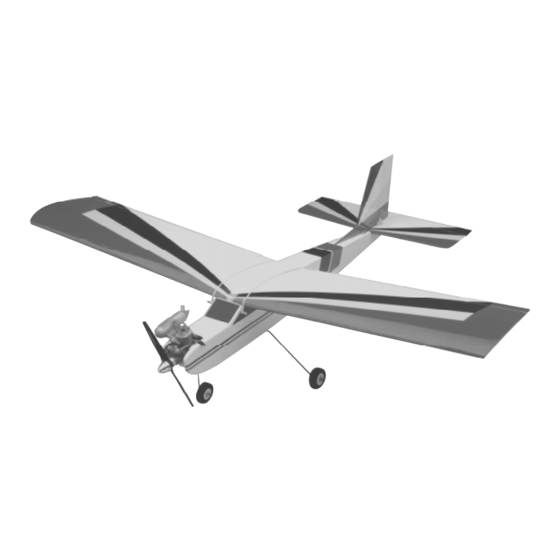
- Page 1 The Right Flyer 40T Mk.II is distributed exclusively by Global Hobby Distributors 18480 Bandilier Circle Fountain Valley, CA 92728 All contents copyright © 2000, Global Hobby Distributors Version V.1.0 2/00...
-
Page 2: Table Of Contents
Fuel Tank..............16 Introduction.............3 Stopper Assembly..........16 Kit Contents............4 Installing the Stopper........17 Metric Conversion Chart........5 Fuel Tank Installation........17 Full Size Hardware Drawings........6 Servo Installation...........18 Additional Items Required........7 Installing the Fuselage Servos......18 Tools and Supplies Needed........7 Installing the Aileron Servo Tray.....18 Field Support Equipment Needed......7 Installing the Aileron Servo......19 Wing Assembly............8 Throttle Pushrod............20... -
Page 3: Introduction
Right Flyer 40T Mk.II. The Right Flyer 40T Mk.II was designed by expert modelers to be one of the best trainer airplanes available today. It features a constant cord wing with a flat bottom airfoil for superior slow flight handling and forgiving flight characteristics. -
Page 4: Kit Contents
We have organized the parts as they come out of the box for easier identification during assembly. Each photo below represents the parts that are required in a main section of the assembly process. Before you begin assem- bly, group the parts like we show. This will ensure you have all of the parts before you begin assembly. It will also help you become familiar with each part. -
Page 5: Metric Conversion Chart
{1} Prebent Nose Gear Wire {2} 2mm x 95mm Threaded Wires w/L-Bends {1} 60mm Diameter Wheel {2} 2mm x 415mm Threaded Wires w/Z-Bends {1} Nylon Nose Gear Bracket {1} 2mm x 530mm Threaded Wire w/L-Bend {1} Nylon Nose Gear Steering Arm {1} 2mm x 590mm Threaded Wire w/L-Bend {1} Nylon Spacer {2} Wheel Collars... -
Page 6: Full Size Hardware Drawings
Listed below are full size drawings of the small hardware items included with the Right Flyer 40T Mk.II. Use these drawings to familiarize yourself with each part. Please refer back to this page to locate the proper hardware items when they are needed for a particular assembly step. These drawings are especially helpful when trying to identify the different size screws or nuts used in a particular step. -
Page 7: Additional Items Required
Magnum 4-Way Wrench # 237420 Global guarantees this kit to be free from defects in both material and workmanship, at the date of purchase. This does not cover any components parts damaged by use, misuse or modification. In no case shall Global's liability exceed the original cost of the purchased kit. -
Page 8: Wing Assembly
Photo # 3 PARTS REQUIRED {1} Left Wing Half w/Aileron & Hinges {1} Right Wing Half w/Aileron & Hinges {1} Plywood Dihedral Brace W-3 {1} Precovered Plywood Wing Doubler INSTALLING THE DIHEDRAL BRACE 1) Look at the surface of each root rib on both The dihedral brace is cut in the shape of a "V". -
Page 9: Installing The Wing Doubler
14) Remove the doubler. Using a modeling 9) Mix a generous amount of Kwik Bond 30 knife, carefully remove the covering from just inside Minute Epoxy. Apply a thin layer of epoxy to the the outline. exposed half of the dihedral brace, the inside of the plywood box in the second wing half, and the entire When cutting through the covering, cut with surface of both root ribs. -
Page 10: Aligning The Wing
4) When satisfied with their fit, use a pencil and place a mark on each dowel were they exit the fuse- lage sides. Remove the two dowels. PARTS REQUIRED 5) Mix a small amount of Kwik Bond 30 Minute {1} Horizontal Stabilizer w/Elevator & Hinges Epoxy. -
Page 11: Mounting The Horizontal Stabilizer
the stabilizer with the centerline marks drawn on the When cutting through the covering to remove fuselage. When those are aligned, hold the stabilizer it, cut with only enough pressure to only cut through the covering itself. Cutting into the balsa may in that position using masking tape. -
Page 12: Vertical Stabilizer Installation
15) Glue the triangle stock into place using a When cutting through the covering to remove generous amount of Kwik Bond Thick C/A. Allow it, cut with only enough pressure to only cut the glue to cure completely before proceeding. through the covering itself. -
Page 13: Hinging The Elevator
3) Slide a small piece of waxed paper between 10) When you are satisfied with the fit, hold the the aileron torque rod and the trailing edge of the wing. elevator tight against the stabilizer and rotate the el- See photo # 13 below. evator down about 45º. -
Page 14: Installing The Main Gear Wheels
2) Insert the 90º bend of each main gear wire Photo # 16 into the predrilled holes in the mounting slot. See photo # 14 below. Photo # 14 9) Repeat steps # 7 and # 8 to install the second wheel on the opposite axle. -
Page 15: Installing The Nose Gear Wire
7) Remove the nose gear. With the pushrod wire INSTALLING THE NOSE GEAR WIRE still in place, connect the Z-bend in the pushrod wire 2) Thread one 3mm x 6mm machine screw into to the predrilled hole in the steering arm. Slide the the side of the nylon steering arm. -
Page 16: Engine Mounting
the holes in the engine mount. Install the engine us- ing four 3mm x 19mm machine screws, eight 3mm flat washers and four 3mm nylon insert nuts. Tighten PARTS REQUIRED the screws and nuts completely to secure the engine {4} 3mm x 19mm Machine Screws in place. -
Page 17: Installing The Stopper
front of the stopper. Slide the 20mm diameter front If the tubes do not fit right, remove the stopper plate over the tubes at the front of the stopper and assembly and adjust them before proceeding. slide the 17mm diameter rear plate over the tubes at the rear of the stopper. -
Page 18: Servo Installation
When installing the fuel tank, make sure the top 2) Position the servos into the preinstalled servo of the tank is facing the top of the fuselage. tray making sure you run the servo wires out the pre- cut hole in the forward servo tray bulkhead. Note the 14) When properly aligned, the front portion of position of each of the servo output shafts. -
Page 19: Installing The Aileron Servo
hole and the "V" shape should match the angle of 8) When satisfied with the fit, remove the servo the top wing sheeting. See photo # 30 below. tray assembly. Mix up a generous amount of Kwik Bond 30 Minute Epoxy. Apply a thin layer of epoxy Photo # 30 to the gluing surfaces of each of the two hardwood blocks. -
Page 20: Throttle Pushrod
After installing the adjustable servo connector apply a small drop of Kwik Bond Thin C/A to the nut. This will prevent the connector from loosen- PARTS REQUIRED ing during flight. {1} 2mm x 415mm Threaded Wire w/Z-Bend {1} Adjustable Servo Connector 5) Plug the throttle servo lead into your receiver INSTALLING THE PUSHROD WIRE and turn on the radio system (please refer to your... -
Page 21: Elevator Pushrod
and your radio is equipped with digital or manual end INSTALLING THE PUSHROD point adjustments, make those adjustments using the 4) Using a modeling knife, remove the cover- transmitter features (see your radio instruction manual ing from over the elevator pushrod exit hole in the for further details). -
Page 22: Adjusting The Elevator Pushrod
10) Attach the servo arm to the servo. The servo 17) Pull back completely on the elevator con- arm should be centered on the servo and point toward trol stick. Using a ruler, measure the amount the the middle of the fuselage. Install the servo arm re- trailing edge of the elevator moves up. -
Page 23: Installing The Pushrod
the servo arm using a 5/64” drill bit so the servo clevis attachment holes are directly over the hinge connector will fit. When you thread on the nut, don't line. Also make sure the control horn is parallel with tighten it completely. You don't want the connector the bottom of the rudder. -
Page 24: Adjusting The Rudder Pushrod
12) Use a couple of pieces of masking tape to adjustments, make those adjustments using the trans- hold the rudder centered. mitter. If your radio does not have this feature, you can adjust the clevis and servo arm. If the rudder is 13) Using a modeling knife, cut a piece of fuel moving more than 5/8”... -
Page 25: Adjusting The Aileron Linkage
3) Using a 5/64” drill bit, enlarge the fourth hole ADJUSTING THE AILERON LINKAGE out from the center of each side of the servo arm. 10) With your radio system still plugged in and Insert the L-bends in the 2mm x 95mm pushrod wires turned on, check the aileron control surface direction down through the holes. -
Page 26: Installing The Switch
2) To fill the fuel tank, remove the fuel lines 8) The receiver is mounted directly behind the from both the carburetor and the muffler. Fill through fuel tank. Using a 5/64” drill bit, drill a hole in the the fuel pickup line and watch for excess fuel coming left side of the fuselage, about 1/2”... -
Page 27: Balancing
Moving the balance point forward will cause rate settings. the airplane to be more stable, but less responsive. Do not fly the Right Flyer 40T Mk.II beyond the 7) Check the receiver antenna. It should be fully recommended balance range or an uncontrollable extended and not coiled up inside the fuselage. -
Page 28: Abc's Of Flying
5) No high-lines, telephone lines or electrical Since you've chosen the Right Flyer 40T Mk.II, lines should be near the flying site. If your plane you've avoided the most common mistake beginners... - Page 29 8's and rectangular patterns. Don't go to fast! Now try a turn (before the airplane gets too far The Right Flyer 40T Mk.II is not a car! This will away). To turn, apply aileron until the wing drops also give you a chance to make sure the nose gear about 15 degrees (or the wing tip is just below the steering tracks straight.
- Page 30 The descent should be gentle so let the nose drop correction. Typically, you will need very little down elevator as well. Remember to move the stick only about 10 to 20 degrees. Keep the wing level unless a turn is required. If you must turn, bank as usual to small amounts at a time.
-
Page 31: Glossary Of Terms
Hinges: Usually made out of plastic, the hinges con- nect the control surfaces to the stabilizers or wing. Adjustable Connector: Connects to the servo arm. They pivot allowing the control surface to move. The pushrod wire passes through the connector and is held in place with a set screw. -
Page 32: Notes
Vertical Stabilizer: Mounted on the rear of the air- ____________________________________________ plane, it works with the rudder to turn the airplane. It ___________________________________________ also gives the airplane vertical stability. _____________________________________________ ____________________________________________ Wing Hold Down Dowels: Round pieces of hard- _____________________________________________ wood dowels inserted through the fuselage at the front ____________________________________________ and back of the wing. -
Page 35: Product Evaluation Sheet
Simply fold this form on the dotted lines, seal with tape and mail it to us. Do not use staples and make sure our address faces out. 1) Kit: Right Flyer 40T Mk.II 7) Was any of the assembly difficult for you? If yes, please explain. - Page 36 Post Office will not deliver without proper postage Global Hobby Distributors Attn: Customer Care 18480 Bandilier Circle Fountain Valley, CA. 92728-8610 Fold along dotted line...
Need help?
Do you have a question about the Right Flyer 40T Mk.II and is the answer not in the manual?
Questions and answers