Table of Contents
Advertisement
Quick Links
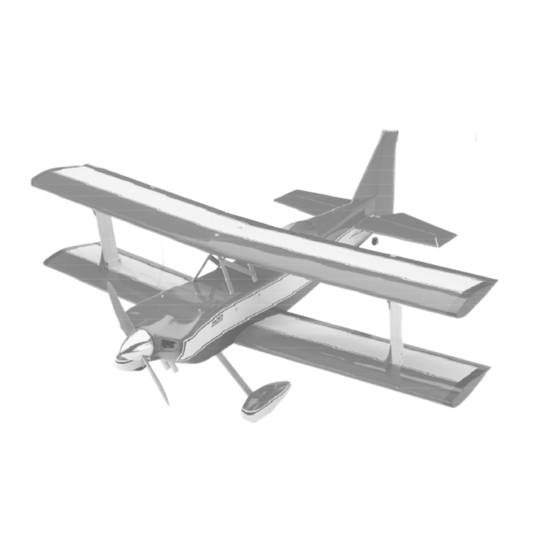
.46 SIZE AEROBATIC ARF PERFORMANCE BIPLANE
.46 SIZE AEROBATIC ARF PERFORMANCE BIPLANE
.46 SIZE AEROBATIC ARF PERFORMANCE BIPLANE
.46 SIZE AEROBATIC ARF PERFORMANCE BIPLANE
.46 SIZE AEROBATIC ARF PERFORMANCE BIPLANE
Instructions for Final Assembly
Would you like to fly your own Ultimate Biplane? Do you want to be flying in a weekend?
Are you ready for an aerobatic 46 size performance biplane? Then you've chosen wisely.
The Global ARF Ultimate was made for you. Features like an all balsa and plywood built up
airframe, just like you'd do it yourself from a kit. A generous tail section combined with a
long fuselage moment and swept wings make this an aerobatic performer that you'll always
want to fly. A super strong metal wing center cabane system with outer plywood interplane
struts hold everything together when you're performing snap rolls and inverted spins. To go
along with this we've provided a prepainted four color cowling, prepainted wheel pants and
a clear molded canopy. There is no other aerobatic biplane in it's class that is easier to
assemble or that flys better. We know you'll enjoy building the Ultimate, but you bought this
airplane to fly. And that's what it does best. Set up for sport flying, it's predictable and
tracks like it's on rails. Deceivingly easy to fly, change the set-up parameters and you'll
push the envelope like an experienced airshow performer. Complete inverted flat spins and
torque rolls like you've never performed before!
Version V1.0
3-99
Kit # 123820
All Contents © Copyright 1999
Advertisement
Table of Contents

Related Manuals for Global Ultimate

Summary of Contents for Global Ultimate
- Page 1 .46 SIZE AEROBATIC ARF PERFORMANCE BIPLANE Instructions for Final Assembly Would you like to fly your own Ultimate Biplane? Do you want to be flying in a weekend? Are you ready for an aerobatic 46 size performance biplane? Then you’ve chosen wisely.
-
Page 2: Table Of Contents
Installing the Throttle Linkage....14 Global guarantees this kit to be free from defects in both material and workmanship, at the date of purchase. This does not cover any components parts damaged by use, misuse or modification. In no case shall Global's liability exceed the original cost of the purchased kit. -
Page 3: Kit Contents
This instruction manual is designed to help you build a straight, great flying airplane. Please read this manual thoroughly before beginning assembly of your new Ultimate Biplane. Use the parts listing below to identify and separate all parts before beginning assembly. - Page 4 Magnum 12V Fuel Pump (# 237377) Magnum Power Panel (# 237390) Magnum Locking Glow Clip (# 237440) Global Field Buddy Flight Box (# 233072) Global 12V Battery (# 110171 ) Magnum 4-Way Wrench (# 237420) To convert inches into millimeters: Inches x 25.4 = MM 1/64”...
-
Page 5: Align The Bottom Wing
**NOTE** Please trial fit all the parts. Make sure that you have the correct parts and that they fit and are aligned properly before gluing! This will ensure proper assembly. Since the Ultimate Biplane is hand made from natural materials, every plane is unique and minor adjustments may have to be made. How- ever, you should find the fit superior and assembly simple. -
Page 6: Installing The Wing Bolt Doubler
11) Mix up a small amount of Kwik Bond 6) Remove the wing from the wing 5 Minute Epoxy and use it to glue the wing saddle. Drill out only the holes in the ply- doubler to the wing. Allow the epoxy to fully wood wing mounting block using a 7/32”... -
Page 7: Mounting The Horizontal Stabilizer
2) Remove the elevator halves from the MOUNTING THE HORIZONTAL STABILIZER stabilizer. Using a ruler and pen, locate and 6) With the stabilizer held firmly in place, mark the centerline of the horizontal stabi- use a pen and draw a line where it and the fu- lizer at the trailing edge and place a mark. -
Page 8: Vertical Stabilizer Mounting
However, wing incidence is criti- cal in a biplane to achieve proper flight per- formance. Incidence is the angle the flying surfaces flow through the air. The Ultimate should be set with the stabilizer at 0º, the lower REMOVE wing at 0º, and the top wing at 0º... -
Page 9: Installing The Interplane Struts
6) Locate and remove the covering from 2) With the airplane setting in the stand, over the two predrilled wing hold down holes attach an incidence meter to the horizontal sta- in the top wing. These holes are located down bilizer. -
Page 10: Mounting The Top Wing
16) When completely satisfied with the 10) There are two predrilled holes alignment of the top wing use threadlock on all through each strut mounting block in the bot- of the metal cabane screws and nuts and tighten tom wing. Using a modeling knife, remove them completely to lock the wing's alignment the covering from over these holes. -
Page 11: Install The Tail Wheel Assembly
the elevator in until it is tight against the trail- 7) Mix up a small amount of Kwik Bond ing edge of the stabilizer. The maximum hinge 5 Minute Epoxy. Apply the epoxy to only gap should be no more than 1/32”, but there those parts of the tail wheel wire that will be should be about a 1/16”... -
Page 12: Install The Tail Wheel
11) Mix up a small amount of Kwik Bond The waxed paper will prevent epoxy from 30 Minute Epoxy. Remove the rudder and gluing the torque rod to the trailing edge of apply a thin layer of epoxy to only the tab on the wing. -
Page 13: Engine Mounting
ALIGNING THE MOTOR MOUNT 5) The engine is mounted sideways on the PARTS REQUIRED firewall. Using a ruler and pen, measure and draw a vertical centerline on the firewall. {2} Nylon Mounting Beams {4} 3mm x 20mm Machine Screws {4} 3mm x 25mm Machine Screws 6) Measure down from the top of the fu- {16}3mm Flat Washers selage 1-1/2”... -
Page 14: Mounting The Engine To Firewall
10) Hold the motor mount assembly up 2) Using 220 grit sandpaper carefully to the firewall and double check that the four smooth each end of the two tubes. This will intersecting lines line up with the four pre- prevent the fuel line from being cut. drilled holes in the motor mount. -
Page 15: Fuel Tank Installation
8) When satisfied with the alignment of (FOUR STROKE SET UP) Photo # 23 the stopper assembly tighten the 3mm x 20mm Enlarge hole in firewall machine screw until the rubber stopper ex- NYLON to allow clevis to pass CLEVIS pands and seals the tank opening. -
Page 16: Installing The Wheel Pants
2) Mix up a small amount of Kwik Bond 5) Slide two 4mm nylon spacers over the 5 Minute Epoxy. Use a couple of small dabs axle screw and up against the wheel. Thread of epoxy to glue the balsa gear cover (D-29) one 4mm hex nut onto the axle screw. -
Page 17: Aileron Servo
11) When satisfied with the alignment, 3) Hold the two plates in place and trace secure the wheel pants in place by installing around them using a pen. Remove the plates two 2mm x 8mm wood screws through the and using a modeling knife, remove the cov- two predrilled holes in the gear bracket and ering from just inside the lines. -
Page 18: Installing The Servo Tray
servos should be pointing towards the front SNAP SERVO Photo # 30 of the fuselage. See photo # 32 below. KEEPER PUSHROD WIRE Photo # 32 CLEVIS CONTROL HORN E = ELEVATOR 11) When satisfied with the alignment, T = THROTTLE R = RUDDER install the servo arm set screw and remove the masking tape from the ailerons. -
Page 19: Installing The Throttle Connector
8) Using a 1/16” drill bit, drill a hole 5) Remove the excess throttle pushrod wire through the side of the fuselage for the an- using wire cutters. See photo # 33 below. tenna to exit. Route the antenna out the fuse- CONNECTOR Photo # 33 lage and secure it to the vertical fin using a... -
Page 20: Rudder Pushrod
2) When satisfied with the alignment, use 10) Slide the pushrod back into the a 3/32” drill bit and the control horn as a guide pushrod housing. Snap the clevis onto the rud- and drill the mounting holes through the rud- der control horn and use a couple of pieces of der. -
Page 21: Elevator Pushrod
4) Using a 3/32” drill bit, drill a hole through the center of the nylon joiner plate. Slide a 2mm washer onto the 2mm x 20mm PARTS REQUIRED machine screw. Slide the screw through the {2} Nylon Control Horns w/Nylon Back Plates center hole of the nylon joiner plate. -
Page 22: Installing The Control Horns
10) Using a modeling knife, cut off the 19) Move the elevator halves up and pushrod housings at this mark. down. There may be some flex present in the pushrod just before it gets to the elevator 11) Slide the nylon pushrods into the servo. -
Page 23: Aileron Links
3) Using a pen, place a mark on both sides 4) Mount the control horns to the aile- of the canopy at the front and back. Place the rons by inserting the 2mm x 15mm machine marks where the canopy meets the bottom of screws through the control horn mounting the black stripe on the fuselage sides. - Page 24 2) Using a Dremel Tool with a sanding 7) Remove the cowl and enlarge the holes drum attachment, carefully open the two air in only the cowl using a 5/64” drill bit. Rein- inlets in the front of the cowl. Trim away a stall the cowl and secure it in place using the small amount at a time so you don't remove four wood screws.
-
Page 25: Lateral Balance
Do not use the aerobatic settings for ini- less stable. Moving the balance point forward tial test flying or sport flying. will cause the Ultimate to be more stable, but less responsive. Do not fly the Ultimate be- yond the recommended balance range or an... -
Page 26: Flying
______________________________________________ ______________________________________________ _____________________________________________ The Ultimate is designed for those pilots who ______________________________________________ are experienced in flying sport models. It is ______________________________________________ in no way a trainer. If you do not feel com-... -
Page 27: Notes
After you have test flown and done the initial trim changes to the aircraft, use the Trim Chart below to begin trimming your airplane. Following and adhering to this chart will result in the ability to diagnose trim problems and correct those problems using the simple adjustments shown below. Making these observations and related corrections will result in a truer, better flying airplane. - Page 28 Since you love your new Ultimate Biplane, now how about this Global ARF performance airplane to go along with it? SPECIFICATIONS: Length....47.25in Span.......52in Area....570sq.in Flying Weight...5-5.5lbs Engine..45-53 2-stroke 52-60 4-stroke Radio....4 channel All Wood Construction Prebent Aluminum Landing Gear Prepainted Fiberglass Cowling...
- Page 29 Since you love your new Ultimate Biplane, now how about this Global ARF performance airplane to go along with it? SPECIFICATIONS: Length....42in Span.......52in Area....362sq.in Flying Weight...5-5.5lbs Engine..45-53 2-stroke 52-60 4-stroke Radio....4 channel All Wood Construction Custom Spinner Prepainted Fiberglass Cowling...
- Page 30 Since you love your new Ultimate Biplane, now how about this Global ARF performance airplane to go along with it? SPECIFICATIONS: Span.......59in Area....620sq.in Empty Weight..3.5lbs Engine..40-46 2-stroke 52-60 4-stroke Radio...4-5 channel All Wood Construction Ready for Retracts Prepainted Fiberglass Cowling...
- Page 31 Simply fold this form on the dotted lines, seal with tape and mail it to us. Do not use staples and make sure our address faces out. 1.) Kit: Ultimate Biplane .46 (123820) 7.) Was any of the model's assembly difficult for you? If yes, please explain.
- Page 32 Place Stamp Here Global Hobby Distributors Attn: Customer Service Department 18480 Bandilier Circle Fountain Valley, CA. 92728 Fold along dotted line...
Need help?
Do you have a question about the Ultimate and is the answer not in the manual?
Questions and answers