Advertisement
Quick Links
Advertisement

Summary of Contents for Infanor SMT-BD1/m
- Page 1 SMT-BD1/m SMT-BD1/m Positioner ® INFRANOR SMT-BD1/m...
- Page 2 SMT-BD1/m SMT-BD1/m...
- Page 3 SMT-BD1/m WARNING ! This is a general manual describing a series of servo amplifiers having output capability suitable for driving AC brushless sinusoidal servo motors. This manual may be used in conjunction with appropriate and referenced drawings pertaining to the various specific models.
- Page 4 SMT-BD1/m SMT-BD1/m...
-
Page 5: Table Of Contents
2 - MAIN PROTECTIONS........................... 11 2.1 - STORED PROTECTIONS........................11 2.2 - FUSE PROTECTION OF THE SMT-BD1/M DRIVE VERSION 220 VAC..........11 2.3 - FUSE PROTECTION OF THE SMT-BD1/M DRIVE VERSION 400 VAC..........12 CHAPTER 3 - INPUTS-OUTPUTS ........................13 1 - CONNECTORS ............................. - Page 6 SMT-BD1/m 4 - DRIVE COMMISSIONING AND ADJUSTMENT.................... 25 4.1 - PARAMETER SETTING OF MOTOR AND DRIVE ................26 4.2 - MOTOR / DRIVE PARAMETER SETTING WITH A VERTICAL LOAD..........26 4.3 - SAVING THE DRIVE PARAMETERS ....................27 4.4 - ENABLING ............................. 30 4.5 - MANUAL MOVE .............................
-
Page 7: Chapter 1 - General Description
- one logic board with DSP (Digital Signal Processing). The SMT-BD1/m positioner can operate as a stand-alone system or in connection with a PLC or a PC. It can execute up to 128 motion sequences. The sequences can generate position, speed or torque motions. -
Page 8: Chapter 2 - Specifications
"fusing" mode) DRIVE Urated Imax (Arms) Max. authorized rated current (Arms) TYPE (Vrms) of the drive No fan* Fan 1* Fan 2* SMT-BD1/m-220/04 SMT-BD1/m -220/08 SMT-BD1/m-220/12 13.8 SMT-BD1/m-220/17 17.7 SMT-BD1/m-220/30 30.8 SMT-BD1/m-220/30r 30.8 SMT-BD1/m-220/45 48.6 SMT-BD1/m-220/45r 48.6... -
Page 9: Current Ratings For 400 Vac Drive Version
SMT-BD1/m Compliance with the standards: CE approval for - EMC standards multi-axis operation in the BF rack with mains Immunity: CEI standards 801- 2 - 3 - 4 filter BF35 or 70 or in single-axis racks BM20A or Conducted and radiated disturbances: EN 55011,... -
Page 10: Other Specifications
SMT-BD1/m 1.3 - Other specifications PWM switching frequency 10 kHz Current regulator (PI) adjusted to motor Current loop bandwidth Cut-off frequency for 45° phase shift > 1 kHz Internal current limitation Imax: 20 % to 100 % and I rated: 20 % to 50 %... -
Page 11: Main Protections
- via the error RESET input of X4, pin 13, - by switching off the drive power supply. 2.2 - FUSE PROTECTION OF THE SMT-BD1/M DRIVE VERSION 220 VAC F1 : Control of the average DC current of the power board supply. -
Page 12: Fuse Protection Of The Smt-Bd1/M Drive Version 400 Vac
SMT-BD1/m 2.3 - FUSE PROTECTION OF THE SMT-BD1/M DRIVE VERSION 400 VAC F2 : Control of the average DC current of the logic board supply. DRIVE TYPE F2 - LOGIC SMT-BD1/m-400/15 SMT-BD1/m-400/30 SMT-BD1/m-400/45 SMT-BD1/m-400/60 Chapter 2 - Specifications... -
Page 13: Chapter 3 - Inputs-Outputs
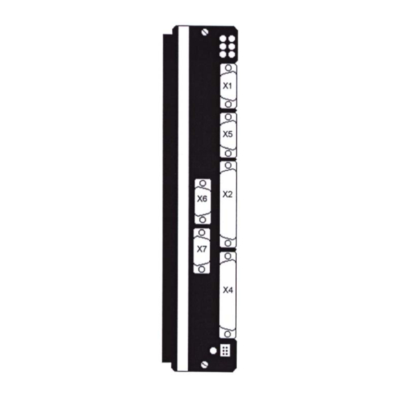
SMT-BD1/m Chapter 3 - Inputs-Outputs 1 - CONNECTORS 1.1 - Rack connectors For the 400 VAC drive version, see manual BF/400 RACK. For the 220 VAC drive version, see manuals SMT-BM20A SINGLE-AXIS RACK or BF RACK. 1.2 - Drive connectors... -
Page 14: X1: Resolver Connector
SMT-BD1/m 2 - X1: RESOLVER CONNECTOR Sub D 9 pins female. FUNCTION REMARKS TC (pin H sensor connector) If thermal switch connected to X1 Shield connection If no "360°" connection on the connector TC (pin I sensor connector) If thermal switch connected to X1... -
Page 15: X4: Command Connector - Subd 25 Pins Male
SMT-BD1/m 4 - X4: COMMAND CONNECTOR - Sub D 25 pins male FUNCTION REMARKS Limit switch + Positive or negative logic Limit switch - Positive or negative logic 0V limit switch ENABLE Positive or negative logic 0 Volt ENABLE Positive or negative logic... -
Page 16: X5: Rs-232 Connector - Subd 9 Pins Male
SMT-BD1/m 7 - X5: RS-232 CONNECTOR - Sub D 9 pins male FUNCTION REMARKS GND (shield connection if no "360°" connection on the connector) Transmit data RS 232 Receive data RS 232 Transmit data RS 422 Transmit data RS 422... -
Page 17: Logic Outputs Seq, Pos, Speed, Ok, Out1 To Out8
SMT-BD1/m 9.3 - LOGIC OUTPUTS SEQ, POS, SPEED, OK, OUT1 TO OUT8 SMT-BD1/m 24 V The output current is 350 mA for the 8 outputs OUT1 to OUT8. Logic output PC829 UDN2987A The polarity of these inputs can be reversed by a software parameter (see chapter 6, section 4.3.1 "Inputs -... -
Page 18: Chapter 4 - Connections
SMT-BD1/m Chapter 4 - Connections 1 - CONNECTION DIAGRAMS 1.1 - POWER SUPPLY AND MOTOR CONNECTIONS For the 400 VAC drive, see manual BF/400 Rack. For the 220 VAC drive, see manuals BF Rack or SMT-BM20 A / BMM05F/AF single-axis racks. -
Page 19: Shield Connection On The Connectors
SMT-BD1/m 2.2 - SHIELD CONNECTION ON THE CONNECTORS RULE The shield must never be interrupted over the whole cable length. Self-sticking copper ribbon if necessary, for increasing the shield diameter in order to get it correctly tightened under the clamp... -
Page 20: Motor And Resolver Cables
SMT-BD1/m 2.3 - MOTOR AND RESOLVER CABLES Motors and resolvers are grounded via their housing. Cable ends should have a metal connectors with collars allowing a 360° shield connection. The resolver cable must be pair twisted and shielded (sin, cos, ref.). Motor cables MUST also be shielded. -
Page 21: Chapter 5 - Functional Features
SMT-BD1/m Chapter 5 - Functional features 1 - DESCRIPTION OF THE LOGIC INPUTS-OUTPUTS 1.1 - LOGIC INPUTS ENABLE Enabling authorized. This signal is a necessary conditions for the motor enabling (see also signal RUN). Enabling signal. The motor can be enabled only when the signals ENABLE and RUN are activated. Use in priority the RUN signal if using the brake control. -
Page 22: Logic Outputs
SMT-BD1/m IN1 to IN8 These inputs allow to define, in natural binary code, the sequence that will be executed. They also allow to define a sequence starting condition. 1.2 - LOGIC OUTPUTS Amp OK This signal indicates that the drive is ready (without error). - Page 23 SMT-BD1/m Reversal of the analog input This function allows to reverse the speed limitation. Analog input Speed limitation Limitation of the reversed speed 0 Volts No limitation Maximum limitation 10 Volts Maximum limitation No limitation Chapter 5 - Functional features...
-
Page 24: Chapter 6 - Commissioning
8, sections 2, 3 2 - INSTALLING THE PC SOFTWARE 2.1 - Basic configuration For running the VDSetup software required for the commissioning of the SMT-BD1/m positioner, the minimum PC configuration must be the following: Pentium processor 75... -
Page 25: Putting Into Operation
SMT-BD1/m When starting, VDSetup is testing the communication between the drive and the PC ports COM1 to COM3. If no communication can be settled, a warning message is displayed and VDSetup is running in off-line mode. For more information in case of communication problems with the drive, see Visual Drive Setup Manual, Chapter 2: Installation of the software. -
Page 26: Parameter Setting Of Motor And Drive
SMT-BD1/m 4.1 - PARAMETER SETTING OF MOTOR AND DRIVE (shortcut button The parameter setting software tool allows a quick commissioning thanks to the WIZARD function. Clicking on the shortcut button will open a new window with several notebook tabs: Servo motor, current limit, speed limit, encoder output, servo loop. -
Page 27: Saving The Drive Parameters
SMT-BD1/m In case of loud noise in the motor at standstill or when running, check the rigidiy of the transmission between motor and load (backlashes in gearings and couplings). If necessary, renew the Auto-tuning procedure by selecting a lower bandwidth. If the problem remains, renew the Auto-tuning procedure while activating the antiresonance filter. -
Page 28: New Functions
SMT-BD1/m Inputs polarity: Defines the polarity of the optocoupled inputs START, STOP, JOG+, JOG-, IN1 to IN8: if the box is marked with "1", the input is active on +24 V. Sequence control: The inputs IN1 to IN7 can be used for selecting sequences (checked off). There are maximum 128 sequences that can be selected this way by the inputs IN1 to IN7 (in all-binary code). - Page 29 SMT-BD1/m Forward: with the function "Reset counter" activated, if this parameter is activated (ticked off), the motor turns in positive direction for an absolute displacement lower than the value of the "Reset counter" parameter, if this parameter is not activated (not ticked off), for an absolute displacement lower than the value of the "Reset counter"...
-
Page 30: Enabling
SMT-BD1/m 4.3.4 - MANUAL MOVEMENT PARAMETERS Frame "Manual movement parameters" This menu defines the parameters movement speed, acceleration time and deceleration time during a movement via JOG+, JOG- or via the serial link. Control by means of the shortcut button... -
Page 31: Manual Move
SMT-BD1/m The brake control is enabled (contact open) or disabled (contact closed) according to the drive status (disabled or enabled). 4.5 - MANUAL MOVE The manual move can be made as follows: - via the inputs JOG+ and JOG-: the motor moves at the programmed speed (Manual movement parameters) - via the serial link. -
Page 32: Programmation
SMT-BD1/m 5 - PROGRAMMATION 5.1 - GENERAL DESCRIPTION The sequences programmation is accessible via a sequence editor which is accessible via the shortcut button "Sequence setup" In the "Edit" menu, following functions are accessible: Function "Copy sequence" : copies the highlighted sequence. -
Page 33: Edition Of A Sequence
"Max. motor speed" is modified, all speed parameters in the sequences are also modified. Consequently, when a sequence file is sent to the SMT-BD1/m positioner, it must be programmed before with the correct parameters "Position resolution" and "Max. motor speed". - Page 34 SMT-BD1/m sequence 2: Next = 3 Counter = 2 Counter link = 1 sequence 3: Next = Counter = Counter link = If the execution starts at sequence 1, the programme course will be the following: start at sequence n° 1 then link (parameter "Next") to sequence Sequence 1 n°...
- Page 35 SMT-BD1/m Diagram of the procedure with switch: Switch detection Switch research (programmed speed) (origin position) Load the Pos value in the Start Return to origin position counter position (speed/4) If Switch = Y and Zero = Y or Origin = Y, the speed reversal is made by the switch detection or by a limit switch.
-
Page 36: Programme Execution
The shortcut button "Oscilloscope" => displays the oscilloscope screen. NOTE: Series SMT-BD1/m drives do not allow to display more than two oscilloscope channels at the same time. Channel 3 cannot be significant and must consequently not be validated. For the detailed operation of the oscilloscope, see the VISUAL DRIVE SETUP Manual, Chapter 6: Oscilloscope. - Page 37 SMT-BD1/m The signals which can be displayed are the following: Signal Unit Description Speed Speed monitor Speed ref Speed input command Imes % Imax Current monitor % Imax Current input command % Imax 4Q current monitor % Imax Direct current monitor...
-
Page 38: Chapter 7 - Troubleshooting And Maintenance
SMT-BD1/m Chapter 7 - Troubleshooting and maintenance 1 - SYSTEM ERROR If the red LED "SYS" is lit when turning on the drive, the logic board is defective. Check that the EPROM (firmware memory) is correctly plugged on the drive. -
Page 39: Undervolt
If the error occurs when turning on the drive: * Check the DC bus voltage and the terminal voltage of the power transformer secondary: SMT-BD1/m-230/I (DC bus < 370 V and V secondary < 260 V ), all mains variation tolerances included. -
Page 40: Operation Problems
SMT-BD1/m 3 - OPERATION PROBLEMS 3.1 - NO MOTOR MOVEMENT Check that the drive is on. Check that the power supply is on. Check the drive fuses (F1 and F2) and the motor connection. Check the logic wiring of the signals FC+, FC-, ENABLE and RUN (see chapter 8, section 4). -
Page 41: Chapter 8 - Appendix
SMT-BD1/m Chapter 8 - Appendix 1 - USING SMT-BD1/m WITH A DISPLAY TERMINAL 1.1 - CONFIGURATION 1.1.1 - TERMINAL CONFIGURATION - A display with 4 lines of 20 characters each: - A keyboard with: 0..9 keys, ENTER key, arrow keys. - Page 42 SMT-BD1/m 1.2.2 - DISPLAY POSITION SMT-BD1/m øøø 103. The arrow keys allow to move the motor (jog+ or jog-), when the ENABLE and RUN signals are active. The key allows the operator to go back to the main menu. RETURN...
-
Page 43: Smt-Bd1/ Minstructions List
POS:_ 2 - SMT-BD1/m INSTRUCTIONS LIST 2.1 - OVERVIEW The specifications of the SMT-BD1/m positionier serial link are: - 8 data bits, 1 stop bit, no parity, - 19200 baud. The parameters can be sent to the drive by an ASCII terminal using the instructions list given in this manual. Each instruction is coded as 2 ASCII characters with or without parameter. -
Page 44: Instructions List
As there is no parameter in the instruction, the drive sends back the actual number of pole pairs. 2.2 - INSTRUCTIONS LIST All instructions described below are specific of the SMT-BD1/m positioner. Other standard instructions are described in the standard "instructions list manual" of the SMT-BD1 standard drive. - Page 45 This instruction can be sent only if no sequence is executed. The sequence must exist. Unit Second Range 16 s - 16000 s Remark See SMT-BD1/m manual for the "acceleration time" signification. Modify deceleration of a sequence Instruction Parameters 1st parameter: sequence number. 2nd parameter : deceleration time.
- Page 46 This parameter is saved in the positioner memory. Unit Acceleration (absolute movement) Instruction defines the acceleration for absolute movement (MP). Parameters acceleration time Conditions Remark See SMT-BD1/m manual for the "acceleration time" signification. This parameter is saved in the positioner memory. Unit Appendix...
- Page 47 SMT-BD1/m Deceleration (absolute movement) Instruction defines the deceleration for absolute movement (MP). Parameters Deceleration time Conditions Remark See SMT-BD1/m manual for "deceleration time" signification. This parameter is saved in the positioner memory. Unit Stop Instruction SOFF Parameters Conditions Remark Stops all movements except for jog.
-
Page 48: Hardware Adjustments Location
SMT-BD1/m 3 - HARDWARE ADJUSTMENTS LOCATION Current loops (power board) Serial link RS232 Bridge B or C 1 2 3 4 Serial link RS485 Resolver transformation ratio LOGIC BOARD Firmware memory Amplifier address switches Parameters & program Power fuse memory... - Page 49 SMT-BD1/m CURRENT LOOPS ADJUSTMENT A and B OPEN: with auxiliary supply A and B CLOSED: without auxiliary supply For amplifier ratings 70 A and 100 A Appendix...
- Page 50 SMT-BD1/m BRAKING SYSTEM SELECTION ON SMT-BD1/m-220/04w TO 220/60w Braking resistor Braking resistor jumper for 220/04w to 220/17w Braking resistor jumper for 220/30w to 220/60 w SMT-BM20 A single-axis rack: Braking resistor jumper closed. BF-rack: Braking resistor jumper open. NOTE: This braking resistor system selection is only available on « w » referenced drives.
-
Page 51: Adjustment To Various Resolvers
SMT-BD1/m 4 - ADJUSTMENT TO VARIOUS RESOLVERS For the use of other resolvers than those mounted on MAVILOR motors, see X1 wiring diagram below as well as the manufacturer's diagram: Bk/Wh Re/Wh For the use of resolvers with other transformation ratios than 0,5, the Cos and Sin signal amplitude must be adjusted by means of the "P-RES"... -
Page 52: Adjustment To The Motor
SMT-BD1/m 5 - ADJUSTMENT TO THE MOTOR 5.1 - CONFIGURATION OF THE MOTOR THERMAL SENSOR Select jumper MN or OP according to the motor thermal sensor type (PTC or NTC). 5.1.1 - THERMAL SENSOR PTC On motors equipped with a PTC thermal sensor (triggering on high impedance), the amplifier configuration is the following: MN jumper closed and OP jumper open. -
Page 53: I T Protection
SMT-BD1/m 5.2.2 - CURRENT LOOPS ADJUSTMENT ON DRIVES WITH 220 VAC SUPPLY Select the current loop jumpers corresponding to the motor and drive specifications (position B1, B2 or B3). On the MAVILOR motor series BL and MA, the current loops adjustments are made according to the table below:... -
Page 54: I 2 T Protection
SMT-BD1/m Amplifier current Maximum current t1 = Blinking display t2 = current limitation t3 = I t protection Rated current 1 second Time The maximum current duration before the release of the Idyn signal depends on the value of the Rated current and Maximum current parameters. - Page 55 SMT-BD1/m CAUTION In Fusing mode, the amplifier Rated current value must be adjusted in order to be lower or equal to the Maximum authorized rated current of the amplifier (see chapter 2, section Current limitation in Limiting mode When the amplifier RMS current (I...
-
Page 56: Logic Control Adjustment
SMT-BD1/m 6 - LOGIC CONTROL ADJUSTMENT 6.1 - POSITIVE OR NEGATIVE LOGIC INPUTS The logic inputs FC+, FC-, ENABLE, RUN and INDEX of the logic connector X4 can be configurated in positive logic (control by +24 V) or in negative logic (control by 0 V) as described below:... -
Page 57: Serial Link
SMT-BD1/m 24 V Power Aux. relay Power relay ENABLE "ON" "ON" Amp. ready Disable "OFF" Power "OFF" Aux. relay * POWER OK Aux. Power relay relay Power relay ENABLE relay Amp ready "Amp ready" signals of all axes Power ready "Power ready"... -
Page 58: Drive Types
SMT-BD1/m 8 - DRIVE TYPES SMT - BD1 / _ m _ - U / I _ _ / _ - T - B S 1 = RS 232 2 = RS 422 a = Auxiliary analog input 220 or 400 : rated voltage...
Need help?
Do you have a question about the SMT-BD1/m and is the answer not in the manual?
Questions and answers