
Related Manuals for Data Aire MINI DATA ALARM PROCESSOR II

Summary of Contents for Data Aire MINI DATA ALARM PROCESSOR II
- Page 1 DATA AIRE, Inc. MINI DATA ALARM PROCESSOR II Operation and Maintenance Manual Precise Temperature and Humidity Control Air and Water/Glycol Cooled and Chilled Water...
-
Page 3: Table Of Contents
TABLE OF CONTENTS INTRODUCTION............................. Design Features..........................Software Features..........................Protective and Safety Features......................Conditions & Functions Displayed ..................... Alarms Displayed ..........................Historical Data ........................... INSTALLATION .............................. 7- 5 Location Considerations........................Installation and Wiring........................Installing the Optional Remote Alarm Contact ................... MINI-DAP-II OPERATION and PROGRAMMING ..................7-14 Buttons Function .......................... - Page 4 Menu 37 – Restart Mode........................Menu 38 – Start Time Delay ......................Menu 39 – Firestat Temperature Setting ................... Menu 40 – Optional Alarm 1 Message Setting .................. Menu 41 – Optional Alarm 2 Message Setting .................. Menu 42 – Optional Alarm 3 Message Setting .................. Menu 43 –...
- Page 5 Low AC Voltage Warning Alarm ......................TROUBLESHOOTING ........................... 19-23 TYPICAL INTERCONNECTING WIRING ...................... SPECIFICATIONS ............................PARTS LIST ..............................SENSOR CHART ............................REV 8/03...
-
Page 6: Design Features
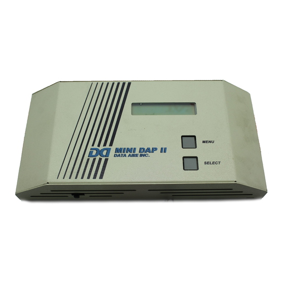
MINI DATA ALARM PROCESSOR II The MINI-DAP II control panel is designed for Data Aire Ceiling systems with one or two cooling stages, one heating stage and a humidifier. This microprocessor based control offers innovative features and “state of the art” technology. -
Page 7: Protective And Safety Features
rotective & Safety features • Metal Oxide Varistor (MOV) snubs the Metal shell enclosure protects panel from transient voltage and protect the circuit electromagnetic interference, environmental board from an excessive power. contamination and handling damage. • • Opto-isolators for 24 VAC signal inputs Protected 24 VAC power input: protect the processor from electrical noise of 1amp fuse for processor portion of the... -
Page 8: Installation And Wiring
Figure 2: Terminal identification and circuit board details. nstallation and Wiring To install and wire the MINI-DAP II panel: 1. Use a Phillips screwdriver to loosen the side screws of the panel. 2. Remove the cover of the MINI-DAP II panel. Place the panel against the wall, mark the location of three mounting holes. -
Page 9: Installation
nstalling the Optional Remote Alarm Contact 1. Turn the Mini-Dap II off. Loosen the side screws and remove the panel cover. 2. Remove four screws that secure the 2 layer board to the base board. See figure 4. 3. Unplug the 2 layer board. -
Page 10: Menu 1 - Temperature & Humidity Setpoints
Figure 4: Board assembly with temperature, humidity sensor and optional summary alarm contact rogramming and Selections Menu Operations and Settings To access the menus setting of Mini-Dap II, NOTE: Menu #2 -OVERRIDE RQST will not Press Menu button to go to menu 1 show if Menu #13- DAY SCHEDULE is set for 1-SET POINTS “N”... -
Page 11: Menu 2 - Override Request
specified on Menu 15-OVERRIDE TIME AUTO: Compressors lead/lag sequence and display will show : “OVERRIDE will change every 168 Hrs of operation. ACTIVE”. Remember Menu 14- OVERRIDE ENBL must be set to “Y” to 7- ADJUSTMENT RATE allow override requests, otherwise this Press Select button to change the setting from 1 menu will never appear. -
Page 12: Menu 11 - Alarm History
EXIT THE MENU - Press Select OVERRIDE HRS: 1 button twice to exit to the normal operation 1 to 12 hours Press Select button to change the Hour Otherwise press Menu button to advance to the This menu specifies the duration of each next menu override request made using “Menu 2- 12-PASSWORD B... -
Page 13: Menu 20 - Set Monday Schedule For Night Setback
Press Menu button to advance to the next menu Press Menu button to advance to the next menu 20- MON. SCHEDULE 24-FRI SCHEDULE Press Select button to display the current setting Similar in all respects to MON SCHEDULE. MON: SETBACK/UP Press Menu button to advance to the next menu SETBACK/UP or ON/OFF 25-SAT SCHEDULE... -
Page 14: Menu 34 - Low Humidity Limit Setting
Press Menu button to advance to the next menu Press Menu button to advance to the next menu 34- LO HUM LIM 39 – FIRE STAT Press Select button to cycle the setting of the Press Select button to view the current setting low humidity alarm limit from 10% to 90% in 1% FIRE STAT: 100 F increments or Lo Hum lim Disab. - Page 15 humidification. It goes off in one minute when no functions are required. Press Menu button to advance to the next menu 47 – DEHUMIDIFIER • CONT: fan runs continuously during the Press Select button to view the current setting occupied mode or normal mode even when DEHUMID: YES W/ INH (Yes with inhibit) no functions are needed.
-
Page 16: Types Of Operation
4- TMP,HUM,AD CAL 10, 11,12,13. The connector terminal number Press select button to display the temperature indicates the alarm input is on, a dash mark (--) sensor raw value and its calibration offse,t which means the alarm input is off. The alarm inputs is programmed on menu #31. -
Page 17: Occupied Heating Logic
COOL 2 OFF AT TEMPERATURE SETPOINT + TEMPERATURE DEADBAND COOL 1 OFF AT TEMPERATURE SETPOINT OCCUPIED HEATING LOGIC 1. 1 minute delay between stop to start of the reheat. Reheat will be overrided by humidification in the computer room. 2. Heating sequences as follows: HEAT ON AT TEMPERATURE SETPOINT –... -
Page 18: Setback Heating Logic
1. 5 minutes delay between start to start of the compressor ( anti short cycle delay). 2. 2 minutes delay between stop to start of the same compressor. 3. Compressor sequences as follows: COOL1 ON AT TEMP SETPOINT + COOL SETBACK TEMP + TEMP DEADBANB COOL2 ON AT TEMP SETPOINT + COOL SETBACK TEMP + TEMP DEADBANB + .3°F (IF EXISTS) COOL2 OFF AT TEMP SETPOINT + COOL SETBACK TEMP + TEMP DEADBAND (IF EXISTS) COOL1 OFF AT TEMP SETPOINT + COOL SETBACK TEMP... -
Page 19: Unoccupied Schedule Of On/Off Mode
On/Off mode If the time-of-day schedule setting for occupied and unoccupied period on menu #20 to #26 are set for “N/C” or when menu #13- DAY SCHEDULE is set for “N”, the control panel will operate in the “occupied “ mode all the time otherwise it will only operate in the “Occupied “... -
Page 20: Firestat Alarm
9. FIRESTAT ALARM When return air temperature exceeds firestat temperature limit setting (menu #39). All blower, cooling, heating, humidification, and dehumidification functions will be immediately terminated. The audio alarm is activated and “FIRESTAT ALARM” message is displayed. The alarm will disappear when return air temperature drops below the firestat limit setting and all functions will resume. -
Page 21: Low Ac Voltage Warning Alarm
18. FAN OVERLOAD ALARM (optional) This alarm requires a motor overload relay that is wired to the alarm optional input and menu #42,“OPT ALARM 3”, is set for “FAN OVERLD”. When overload relay is energized, alarm will goes off until the alarm condition is corrected. -
Page 22: Temperature Sensor Fail
PROBLEM POSSIBLE CAUSE CHECK OR REMEDY MENU: FAIL Bad menu button (close) or Turn panel off, clean and press on the button is pressed when self- button couple times, make sure the button test is proceeding works freely SELECT: FAIL Bad menu button (close) or Turn panel off, clean and press on the button is pressed when self-... -
Page 23: Smoke Alarm
PROBLEM POSSIBLE CAUSE CHECK OR REMEDY Smoke alarm goes off. Check and Reset the smoke detector. Fire stat alarm activated. System is inhibited until return air temp is below the fire stat limit on Menu #39. Faulty cool 1 stage K2 relay. Use manual diagnostic relay test #2 to test this relay. -
Page 24: Troubleshooting
PROBLEM POSSIBLE CAUSE CHECK OR REMEDY Incorrect configuration. Check setting in Menu #46.it should be set “Computer” for computer room or “Comfort” for office. Refer to humidification logic above. Loose connection. Check connection on pin #8 of TB1. Refer to wiring diagram to check connection between unit and panel. -
Page 25: Typical Interconnecting Wiring
PROBLEM POSSIBLE CAUSE CHECK OR REMEDY Faulty alarm relays K6. Use manual diagnostic relay test #2 to test. High condensate (water) Condensate water builds up in Check the condensate pan and the alarm, all functions the condensate pan. condensate float switch. Make sure the shutdown switch is open. -
Page 26: Specifications
pecifications 24 VAC ± 10% @ 50/60 Hz Power Requirements Current Draw 600 mA with no load 24 VAC ± 10% Control Output signal 24 VAC ± 10% Alarm Input signal Fuse for Power supply F1 1 Amps, 5X20 mm fast- acting miniature fuse Fuse for relay output F2 5 Amps, 5X20 mm fast- acting miniature fuse Optional Remote Contact... -
Page 27: Sensor Chart
HUMIDITY & TEMPERATURE SENSOR CHART FOR MINI-DAP-II DC VOLTAGE vs RELATIVE HUMIDITY DC VOLTAGE vs TEMPERATURE 1.11 10.0% 1.95 37.1% 2.78 63.9% 2.800 44.3°F 2.873 57.5°F 2.948 71.0°F 1.14 11.0% 1.98 38.1% 2.82 65.2% 2.801 44.5°F 2.876 58.0°F 2.951 71.5° 1.17 11.9% 2.01... - Page 28 A Member of the CS Group of Companies © 2003 Data Aire, Inc. Data Aire, Inc. reserves the right to make design changes for the purpose of product improvement or to withdraw any design without notice. MDAP-0803...
Need help?
Do you have a question about the MINI DATA ALARM PROCESSOR II and is the answer not in the manual?
Questions and answers