KELCO F60 Installation Instructions Manual
Digital pump controller
Hide thumbs
Also See for F60:
- Installation & programming manual (48 pages) ,
- Programming instructions manual (20 pages)

Related Manuals for KELCO F60


Summary of Contents for KELCO F60
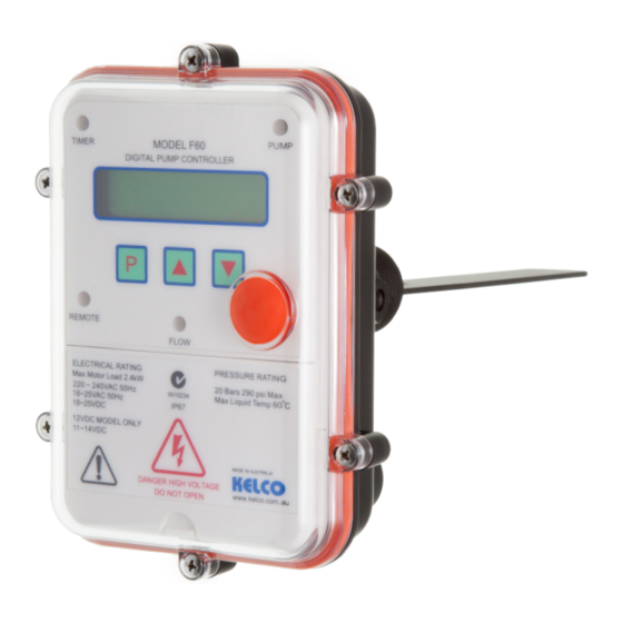
- Page 1 KELCO F60 DIGITAL PUMP CONTROLLER INSTALLATION INSTRUCTIONS Version 180516 KELCO Engineering Pty Ltd Sydney Australia www.kelco.com.au...
- Page 2 VERY IMPORTANT This Kelco controller has been fully tested and calibrated. It is presently unlocked and has a simple program loaded. It is set to operate in a basic way with most of its special functions and features switched off.
-
Page 3: Table Of Contents
Table of Limitations................ Electrical..................The HD Heavy Duty Terminal............Brownout or Blackout..............Cable Gland Assembly..............Electrical Limits................Remote Input ................Wiring Diagrams ................The 12VDC F60 Pump Controller..........F60 Layout..................Table of Controls and their Functions..........Maintenance, Spare Parts, Warranty.......... -
Page 4: Warning Symbols Explained
WARNING This symbol is intended to alert the user to the presence of important operating and maintenance instructions in the literature accompanying the pump controller WARNING This symbol is intended to alert the user to the presence of un-insulated “dangerous voltage” within the pump controller’s enclosure that may be of sufficient magnitude to constitute a risk of severe electric shock. -
Page 5: Important Safety Instructions
WARNING Please read these installation and operating instructions fully and carefully before installing or servicing this controller. The F60 Pump Controller is a mains voltage device. Death or serious injury may result if this product is not correctly installed and operated. -
Page 6: Overview
Overview The F60 digital pump controller is a powerful flexible controller that can be configured in a variety of ways to control a pump and to protect it against running dry. The controller can be set to operate in one of four fundamental modes. Within each mode a number of functions can be selected using the controller’s simple... -
Page 7: Installing The F60
The F60 can be installed in either horizontal or vertical pipe. If it is installed in vertical pipe the flow must be in an upward direction. Do not install this controller on the underside of horizontal pipework. -
Page 8: Before Or After The Air Cell
Before The Air Cell If the F60 is installed before the air cell in the system it will only start the pump on pressure since the initial draw off will be supplied from the air cell. The only change in state the controller will see will be the falling pressure. Choose this... -
Page 9: Warning Message
Never leave the lid off the controller for extended periods. Without its lid in place the F60 is not water resistant and presents a potential shock hazard. Take great care not to splash water onto the controller when the lid is not in place. -
Page 10: Installation
The F60 may have been supplied with either a ¾” or 1” BSP or NPT process connection. A matching female threaded socket or pipe tee must be provided to fit... -
Page 11: Aligning Paddle Assembly
ALIGNING THE PADDLE ASSEMBLY... -
Page 12: Locking The Electrical Assembly Onto The Paddle Assembly
Locking the electrical housing onto the paddle assembly CONTROLLER HOUSING LOCKING SCREW USE 3mm A/F ALLEN KEY PADDLE PIVOT (PROVIDED) TO LOCK THIS BOLT SCREW SECURELY PADDLE ASSEMBLY... -
Page 13: Trimming The Paddle
Trimming the paddle The paddle of the F60 can be cut down to suit the specific pipe size and intended application. Cut the paddle using a hacksaw or tin snips so it clears the sides of the pipe socket and protrudes approximately half to two thirds of the way across the pipe when the controller is screwed into the pipework. -
Page 14: Detaching The Electrical Housing
Detaching The Electrical Housing To allow easy access to the controller’s paddle, the electrical housing of the F60 can be detached from the paddle assembly. Removing the electrical housing allows access to the paddle without the need to disconnect the electrical connections to the controller. -
Page 15: Sensitivity Adjustment
Sensitivity Adjustment Under the end of the electrical housing on the F60 is a red hexagonal dust cap. If you remove this dust cap you gain access to an adjustment screw that allows the paddle preload to be reduced. As supplied the sensitivity adjustment screw is wound fully in. -
Page 16: Limitations
2 ) Do not expose this controller to freezing. If the pipework in which the F60 is installed freezes, the pressure sensor in the controller may fail. If the F60 is to be... -
Page 17: Table Of Limitations
25mm 1” or larger. (There is no upper limit). NOTE: The F60 must NOT be used in hot water applications >60°C. The controller is rated to withstand water pressure to 20 Bars (290 psi) and must not be used in... -
Page 18: Electrical
3 phase pump motors via an appropriate interposing contactor. The F60 requires a 220V to 240V AC 50Hz supply when operated from the mains. It can also be operated from an 18 to 24V AC or DC supply by utilising the low voltage active terminal LV and common neutral terminal N (see the included wiring diagrams). -
Page 19: The Hd Heavy Duty Terminal
We recommend the HD drive be used whenever the controller is used to directly control a pump motor. The HD drive should not be used when the F60 pump controller is connected to external timers, low wattage relays or to any other external device where voltage free contacts are required. -
Page 20: Brownout Or Blackout
Cables The F60 has 3 X M20 cable glands. As supplied, the cable glands are blanked off. To use the glands first punch out the blanking barriers using a suitable punch. The cable glands can accept cable from 7 to 9mm diameter. See attached sketch for assembling the cable gland components. -
Page 21: Cable Gland Assembly
CABLE GLAND ASSEMBLY NOTE Crimp the ears of the strain relief As supplied, cable glands are ring onto cable and pull cable back blanked off. To use a cable gland into slots in the gland housing first punch out the blanking barrier Controller Housing Blanking Barrier Backing Washer... -
Page 22: Electrical Limits
WARNING Do not connect any supply greater than 25VAC or DC to the LV terminal on the F60. The LV terminal is only for use with a low Voltage supply of less than 25V AC or DC. If a Voltage greater than 25V AC or DC is... -
Page 23: Remote Input
F60. The supply to the external switch must be taken from the (LV) terminal (Low Voltage active terminal) of the F60 when the controller is powered from the mains or from a 24VAC source. - Page 24 0.2mm^2 are run to the remote tank (total wire length is 4000 meters). The resistance as measured across the 2 wires back at the F60 (with the tank level switch closed) is 382 Ohms. This is well under the 5,000 Ohm limit. The remote input to the F60 will operate properly provide the wires are separated by sufficient distance that the capacitance between is less than 25nF.
- Page 25 MOST BASIC WAY TO CONNECT THE SUPPLY NOTE: IF THE CONTROLLER IS CONNECTED UP THIS WAY IT WILL NOT DISPLAY ANY INFORMATION ABOUT THE STATE OF THE PUMP IF THE REMOTE SWITCH IS OPEN. IT IS FAR BETTER TO HAVE A PERMANENT SUPPLY ONTO THE ACTIVE AND NEUTRAL TERMINALS AND TO CONNECT A REMOTE SWITCH TO THE LV AND R TERMINALS.
- Page 26 CONTROL OF A SINGLE PHASE PUMP MOTOR WITH A SECONDARY SOURCE BACK UP PUMP AND A REMOTE INPUT SWITCH CONNECTIONS FOR PLUG AND PLAY INSTALLATION...
- Page 27 LOW VOLTAGE AC CONNECTIONS WITH A REMOTE INPUT SWITCH LOW VOLTAGE DC CONNECTIONS WITH A REMOTE INPUT SWITCH...
- Page 28 BASIC SINGLE PHASE WIRING DIAGRAM Maximum 2.4kW CONTROL OF A SINGLE PHASE PUMP MOTOR WITH REMOTE INPUT AND AN EXTERNAL ALARM Maximum 2.4kW...
-
Page 29: Wiring Diagrams
TYPICAL 3 PHASE PUMP CONNECTIONS Coil Neutral supply 3 Phase supply 3 Phase pump motor Contactor CONTROLLING A 3 PHASE PUMP WITH REMOTE INPUT AND AN EXTERNAL ALARM Remote Level or Pressure Switch. Note: Contacts are normally open. Alarm or siren 220 - 240 VAC device 16A maximum load resistive Coil Neutral supply... - Page 30 CONTROLLING A 240VAC SINGLE PHASE PUMP MOTOR WITH THE PUMP CONTROLLER POWERED FROM A LOW VOLTAGE AC SUPPLY Maximum 2.4kW MAINS VOLTAGE REMOTE INPUT CONNECTIONS...
-
Page 31: The 12Vdc F60 Pump Controller
If a remote switch is connected to the 12VDC F60 the supply to the remote switch must be taken from the positive terminal on the controller. The remote switch and its connecting circuit will operate at 12VDC. -
Page 32: F60 Layout
F60 Controls & their Functions... -
Page 33: Table Of Controls And Their Functions
Controls and their Functions No. Description Function Mains Voltage Active For all mains Voltage applications this is the supply Terminal connection. Supply Neutral For all applications this is the supply neutral Terminal connection. Low Voltage Active This is the supply active terminal for all low voltage. Terminal Alarm Relay Terminal This terminal is for connecting an external alarm, it... -
Page 34: Maintenance, Spare Parts, Warranty
Maintenance The F60 is a low maintenance device. If it is correctly installed in a location that is out of direct exposure to the elements it should give a long and reliable life and require no maintenance at all. Factors that may reduce its life are lightning strikes or power surges, failure... - Page 35 PLEASE NOTE: Kelco Engineering Pty Ltd reserves the right to change the specification of this product without notice. Kelco Engineering Pty Ltd accepts no liability for personal injury or economic loss as a consequence of the use of this product. All rights reserved copyright Kelco Engineering Pty Ltd © 2016...
Need help?
Do you have a question about the F60 and is the answer not in the manual?
Questions and answers