Table of Contents
Advertisement
Advertisement
Table of Contents

Summary of Contents for Memotec mychron 3
- Page 1 AiM MyChron3 Basic...
- Page 2 ( exhaust gas or cylinder head ) temperature, the high number of splits per lap ( up to 5 ) and the auto power off after 10 minutes of inactivity make MyChron 3 a great tool for monitoring the kart engine as well as kart and driver performances.
- Page 3 Aim HeadQuarter in Cernusco sul Naviglio – Italy...
-
Page 4: Table Of Contents
The Optical beacon......................12 3 ................14 OW TO INSTALL HRON Installing and changing the display batteries..............14 Installing MyChron 3 on the steering wheel..............15 Installing the RPM clip....................16 Installing the water thermocouple .................17 Installing the EGT thermocouple...................18 Installing the underspark thermocouple ................20 Connecting cables to MyChron 3 ..................21... -
Page 5: Getting Started With M Y Chron 3
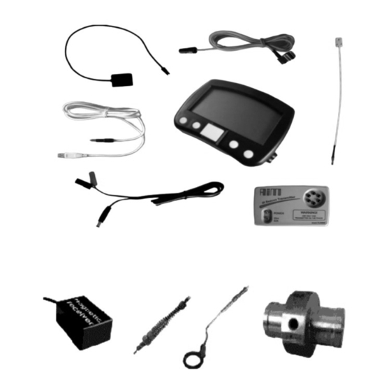
Getting Started with MyChron 3 Aim has developed and tested your MyChron 3 to provide precise and accurate results. Here are the parts of your system: • MyChron 3 Display Unit ( 1 ). • RPM sensor ( 2 ). - Page 6 Fig 1.1 Packing list Also available...
-
Page 7: Mychron 3 And Its Parts
Before installing MyChron 3, please read carefully these installation instructions. It is very important that your MyChron 3 is correctly installed to capture consistent and accurate data. Incorrect installation may result in system malfunction. In the following drawing it is represented MyChron 3 mounted on a kart steering wheel. -
Page 8: The Display
Measure Unit ( Celsius [°C] or Fahrenheit [°F] ), the Night Vision option and the Low Battery Warning, that appears when the batteries are down. Your MyChron 3 has also an automatic power down feature that turns the power off after 10 minutes of inactivity... -
Page 9: The Keyboard
The Keyboard >> VIEW MENU on quit << The Keyboard, composed by four push-buttons, is used for turning the power ON and OFF, configuring the system, recalling the recorded data and clearing the internal memory. The four pushbuttons are used for: MENU/<<... -
Page 10: The Rpm Cable
This clip wire is designed to be plugged directly on the spark plug wire and it is used for RPM pick up from monocylinder 2-4 stroke engines. When running the RPM cable along the chassis between the MyChron 3 display unit and spark plug wire, the RPM cable should be positioned as far as possible... -
Page 11: The Thermocouple
The Thermocouple MyChron 3 supports one temperature sensor. There are 4 types of thermocouples ( temperature sensors ) that are available for selection or subsequent purchase: 1. H O - Water thermocouple1/8 inches type. 2. H O - Water thermocouple M5 type 3. -
Page 12: The Lap Receiver
The arrows on the magnetic receiver need to point to the front and rear of the kart MyChron 3 automatically recognises the lap receiver ( optic or magnetic ) and so no beacon type configuration is needed. -
Page 13: The Optical Beacon
The Optical beacon The optical Beacon Transmitter has to be placed on the trackside to mark laps. Ensure the infrared receiver eye faces the side of the track where the Beacon has been placed, otherwise the system will not record lap time. The Beacon transmitter is powered using 8 AA batteries or an external 12V power cable. - Page 14 To activate this function, please open the Beacon transmitter with a corkscrew and place the clip ( located directly below where the battery pack is is attached to the beacon transmitter board ) either over one of the two connectors ( for low power mode ) or over the two connectors ( for high power mode ).
-
Page 15: How To Install M Y Chron 3
How to install MyChron 3 Now you can start installing MyChron 3 on your kart. It is recommended to follow these instructions in order to preserve your instrument and to capture consistent and accurate data. Installing and changing the display batteries Two AAA alkaline batteries power MyChron 3. -
Page 16: Installing Mychron 3 On The Steering Wheel
Most of steering wheels have existing holes in the three central arms that will accommodate the MyChron 3 display unit. If the steering wheel arms are solid, mark the point where the hole is to be drilled and then indent a drill reference point with a large nail or hole punch, to minimize drill wander. -
Page 17: Installing The Rpm Clip
Installing the RPM clip The RPM sensor clips directly on the spark plug wire. While running the RPM cable along the chassis between the MyChron 3 display unit and the spark plug wire, the RPM cable should be positioned as far as possible from the thermocouple wire. -
Page 18: Installing The Water Thermocouple
Installing the water thermocouple The H O thermocouple can be installed directly into the cylinder head ( if the engine accommodates the thermocouple ) or by using the water thermocouple M5 fitting ( sold separately ) for the M5 type. In the following drawing it is represented how to correctly install the water thermocouple for the M5 type. -
Page 19: Installing The Egt Thermocouple
Installing the EGT thermocouple The Exhaust Gas Thermocouple ( EGT ) should be positioned inside the exhaust header pipe at a distance of 150 mm ( 5.9 inches ) from the exhaust port. In the following drawing it is represented a correct installation of the EGT thermocouple. - Page 20 To install the EGT thermocouple, please follow these instructions: 1. Make a 5 mm ( 0.2 inches ) hole inside the exhaust header; 2. Weld the little nut to the exhaust header in the place where the hole has been drilled; 3.
-
Page 21: Installing The Underspark Thermocouple
Installing the underspark thermocouple When using a Cylinder Head Thermocouple ( CHT ) sensor, always remove the spark plug washer before inserting the spark plug into the sensor. When tightening and loosening the spark plug, minimise movement of the sensor to avoid damage. -
Page 22: Connecting Cables To Mychron 3
Connecting cables to MyChron 3 Once correctly installed all the parts of your MyChron 3, you need to connect them to the main display unit. On the back of the display unit you have to connect the temperature cable to the upper binder and the lap cable to the lower one. - Page 23 While connecting the cables to the main display unit, it is strongly recommended to keep separate the infrared or magnetic receiver, RPM and thermocouple cables, in order to minimize interference between cables.
-
Page 24: How To Use M Y Chron 3
How to use MyChron 3 As you power on your MyChron 3 some information are displayed: here they are described in the same order as they appear: 1_xy Firmware version. MYCHRON 3 Instrument name. MEMORY TOTAL FREE / TEST X LAP Y... - Page 25 MENU/<< button. Night Vision The MyChron 3 display can be set to backlight display so that it is visible during night racing. To set the Night Vision ON or OFF, press button MEM/OK until the required selection appears.
- Page 26 ( if magnetic receiver is employed and you don’t want to see split times). For instance, if your Lap time is about 1 minute, set this parameter at 50 seconds. AIM suggests always installing only one transmitter at the trackside. The Beacon obscuring time can be set between 3 and 59 seconds.
- Page 27 To run this function, after having entered the CONFIGURATION MODE, push MENU/<< till when you don’t see NUMBER OF SPLITS Now push MEM to enter EDIT MODE, then press button MENU/<< until the correct number of splits appears on the display’s lower right corner.
- Page 28 RPM value captured by value MyChron 3. MyChron 3 has five levels for the maximum RPM : 8,000 / 10,000 / 12,000 / 16,000 / 20,000 RPM / 22,000 / 25,000 RPM. To run this function, after having entered the CONFIGURATION MODE, push MENU/<<...
- Page 29 Spark for This option represents the number of spark signals for every Revs engine revolution. A two-stroke engine has one spark signal per revolution, while a four-stroke engine has a spark every two engine revolutions. To set the Spark for Revs, after having entered the CONFIGURATION MODE, push MENU/<<...
- Page 30 Message MyChron 3 text can be displayed in English, Italian, German, language French, Spanish or Slovenian. To run this function, after having entered the CONFIGURATION MODE, push MENU/<< till when you don’t see MESSAGE LANGUAGE Then push MEM to enter EDIT MODE and use MENU/<< or >>...
- Page 31 The standard racing option allows the user to set all the parameters described in the previous paragraphs, while the oval racing option sets some of these parameters (RPM factor, Obscuring time, Split number, Display language) to a fixed value. If you wish to switch from “Standard racing” to “Oval racing”, please turn off your gauge and, then, turn it on pressing buttons >>...
-
Page 32: Utility Functions
10 Hertz ( ten times per second ). This data can be retrieved at a later stage for analysis. MyChron 3 segments data for a session as a test and each test includes the laps completed in that session. To begin recording a new test, please turn off your system off by pressing buttons MEM and VIEW simultaneously, and then turn the system back on. - Page 33 MENU/<< to view a previous lap or button >> for a following lap. If you have configured the MyChron 3 to capture splits, buttons MENU/<< and >> will also scroll through the split times within each lap.
- Page 34 and lap details ( or split details ) appear on the display. To increase scrolling speed through recorded laps hold down buttons MENU/<< and >>. Replaying If you wish to replay detailed data for a lap, you may choose detailed data between an AUTOMATIC way and a MANUAL one.
- Page 35 Through pressing button MEM, the system will return to the “automatic lap replay” mode. To return to general display mode press VIEW. The view data function for the oval racing karts is different View data for oval racing from the one previously described. Press MEM to enter the “recall data from memory”...
-
Page 36: Maintenance
Maintenance Your MyChron 3 does not require any special maintenance. Provided adequate care is taken with the display unit and components, the only maintenance will be to upgrade the firmware when upgrades are released by Aim ( periodically check www.aim-sportline.com... -
Page 37: Mychron 3 And The Computer
MyChron 3 has been designed and developed to be interfaceable with a Pc: through an USB cable it is possible to connect MyChron 3 to a PC in order to both download the data stored in memory and configure your instrument. -
Page 38: Software Installation
Software installation Inside MyChron 3 packaging you can find a CD containing Race Studio 2, a software properly developed to download and analyze the data stored in MyChron 3 memory. To install the software, insert the CD inside the CD-ROM drive: if the autorun option is enabled ( most of cases ), software installation will automatically start, otherwise click twice on SETUP icon. - Page 39 It is now possible to choose the type of installation you prefer: as reported in the following screenshot, it is recommended to place a check beside Typical and to click on Next pushbutton. By using button Browse, it is possible to choose the software installation folder: if you do not wish to change the settings, the software will be installed in the default folder “C:\Program files\AIM”.
- Page 40 Now you have to choose in which folder of the Program menu ( click Start / program ) you prefer to install the software icons. If you click on Next button without modifying the settings, the icons will be created in a folder called AIM. The following window is a recapitulating screenshot: please click on Next button to install the software or Back to modify some installation parameters.
- Page 41 The following screenshot is the final one: please click on Finish button and, then, launch the program. Now, to run the program, click twice on Race Studio 2 icon, which will appear on your computer’s desktop once the installation has finished. To uninstall Race Studio 2 from your computer, please enter Check Panel Mode ( click start / settings / Control Panel ) and click on Software Installation icon.
-
Page 42: Installing The Usb Drivers
12. When the PC and the instrument are turned off, connect the cylindrical connector of the cable to the MyChron 3 USB port and the other end to your PC’s USB port. Now turn on both computer and MyChron 3. - Page 43 In the two following pages it will be reported two examples concerning the USB drivers installation for the Microsoft Windows 98 ™ and Microsoft Windows 2000 ™ operative systems. How to install the USB Driver for Windows 98 ™: 1. Press [ Next ] button when the “Add new Hardware wizard” window appears.
- Page 44 How to install the USB Driver for Windows 2000 ™: 1. Press [ Next ] button when the “Found new Hardware wizard” window appears. 2. Select [ Search for a suitable driver for my device ] and press the [ Next ] button again.
-
Page 45: Configuration Via Software
Configuration via software As previously mentioned, MyChron 3 may be configured both via keyboard and via software, by using Race Studio 2. The “via software configuration” allows the user to configure of his MyChron 3.set some parameters that cannot be set using the keyboard. - Page 46 On the left of the window you will see the icons corresponding to all the Aim instruments supported by Race Studio 2: Dash ST1, MyChron 3, Evo 3, Drack, MyChron Pro, MyChron 2. To select MyChron 3, please click on the corresponding icon.
- Page 47 The user will have to set some parameters, listed here above: • New configuration name; • Data logger type; • Vehicle name; • Vehicle’s wheels number: at choice between 2 and 4; • Beacon receiver’s obscuring time: minimum value 3 and maximum value 59 seconds;...
- Page 48 Here above you can see a short description of all the pushbuttons that can be used to configure your MyChron 3: • General: with this pushbutton you enter the window on page 44; • Visualization: this pushbutton allows you to set the pressure and temperature alarms values and to set the RPM changing gear threshold values;...
-
Page 49: Channels Settings
Channels settings Clicking on the Channels pushbutton it will appear the following screenshot: The only configurable channel is the RPM one: to configure this channel it is necessary to click twice in the box corresponding to the RPM row and the Param. -
Page 50: Configuration Via "Visualization" Pushbutton
Configuration via “Visualization” pushbutton By clicking on the Visualization icon it will appear the following screenshot: The user can set the following parameters: • Display language: at choice between English, Italian, French, German, Spanish and Slovenian; • Maximum RPM value: the user can set both the Sparks for revs ( X1, X2 and /2 ) and Maximum RPM value ( 8,000 / 10,000 / 12,000 / 16,000 / 20,000 / 22,000 / 25,000 RPM );... -
Page 51: Transmitting The Configuration To Mychron 3
Lap: the user can set both the Obscuring time ( in a range between 3 and 59 seconds ) and the number of Split times. Transmitting the configuration to MyChron 3 Once set all the parameters, it is necessary to transmit the configuration to the instrument. - Page 52 If you wish to delete the previous configuration, please press button Si, otherwise press button No and, then, choose the Receive option. By using this option you will be able to download and save the configuration previously stored in the instrument’s memory. Once saved the previous configuration on your PC’s hard disk you can restart the configuration transmission procedure.
-
Page 53: Quick Reference Guide
Quick reference guide Configure MyChron 3 • Press VIEW to turn the system on. • Press MENU/<< to activate the configuration mode. • Press MENU/<< ( previous option ) or >> ( next option ) to scroll through the configuration menu. - Page 54 Press MENU/<< until the correct number appears. • Press >> to alternate between digits. • Press MEM to save or VIEW to quit. Using MyChron 3 Viewing data per best lap time • Press MEM. • Press VIEW to return to main display mode.
- Page 55 • Manual: Press MEM. Press MENU/<< or >> to choose a lap. Press MEM twice. Press MENU/<< or >> to stop “automatic lap replay”. Press MENU/<< to step back by one tenth of a second. Press >> to step forward by one tenth of a second. Press MEM to return to “automatic lap replay”...
Need help?
Do you have a question about the mychron 3 and is the answer not in the manual?
Questions and answers