Table of Contents
Advertisement
Quick Links
Advertisement
Table of Contents

Related Manuals for Luminex Luminex 200


Summary of Contents for Luminex Luminex 200
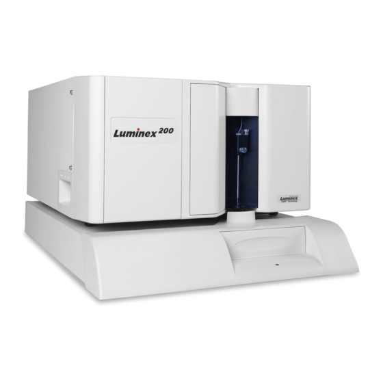
- Page 1 Lum/nex ® Luminex 200™ ® Installation Manual 89-00002-00-167...
- Page 2 Angleterre (TQMUK@aol.com) Luminex Corporation (Luminex) reserves the right to modify its products and services at any time. This guide is subject to change without notice. Although prepared to ensure accuracy, Luminex assumes no liability for errors or omissions, or for any damages resulting from the application or use of this information.
- Page 3 DAMAGE UNLESS SUCH PERSONAL INJURY OR PROPERTY DAMAGE IS CAUSED BY SELLER'S GROSS NEGLIGENCE. 3. Buyer's Use of Product -Buyer agrees that no rights or licenses under Luminex's patents shall be implied from the sale of the Product, except as expressly provided herein, and Buyer does not receive any right under Luminex's patent rights hereunder.
- Page 4 Buyer or made available to Buyer by others. 5. Patent Disclaimer - Neither Seller nor Luminex warrants that the use or sale of the Product will not infringe the claims of any United States or other patents covering the product itself or the use thereof...
- Page 5 (30) days written notice to you. Your rights under this EULA automatically terminate without further action on the part of Luminex if you do not comply with any of the terms or conditions of this EULA. Upon any...
- Page 6 The waiver or failure of Luminex or you to exercise in any respect any right or rights provided for herein shall not be deemed a waiver of any further right hereunder.
-
Page 7: Table Of Contents
About This Manual ........1 The Luminex 200 System ....... . . 1 Hardware. - Page 8 Luminex 200 Installation Manual...
-
Page 9: About This Manual
Luminex 200 System analyzer, Luminex software, computer, monitor, keyboard, mouse, Luminex XY Platform instrument (Luminex XYP™), Luminex Sheath Delivery System (Luminex SD™), barcode reader, sheath and waste containers, and xMAP technology reagents. Hardware The Luminex 200 system includes the following hardware: •... -
Page 10: Xmap Technology Reagents
Classification control microspheres (CON1) • Reporter control microspheres (CON2) • xMAP sheath fluid Required Laboratory The following items are necessary to run the Luminex 200 system. Reagents They are not provided by Luminex. • Household bleach • 70% isopropanol or 70% ethanol •... -
Page 11: Warnings And Notes
Luminex 200 Installation Manual Symbol Description Symbol Description Symbol Description Warning Warning Alternating current (refer to manual) (refer to manual) (ac) Warning Warning Protective ground (refer to manual) (refer to manual) Warning Warning (refer to (refer to manual) manual) Catalog Number... -
Page 12: Safety Precautions
Corporation. Various informational labels appear on the back of Luminex system components. Refer to the Luminex System User Manual for more details about the labels. This caution label appears on the back of the Luminex 200 analyzer and on the Luminex XYP instrument. Figure 1. Fuse Caution Label Do not perform any maintenance or cleaning of the system’s... -
Page 13: Fcc Label
Luminex 200 Installation Manual This voltage label appears on the back of the Luminex 200 analyzer: Figure 3. Luminex 200 Serial Number Label This label appears on the back of the Luminex XYP instrument. Figure 4. Luminex XYP Serial Number Label... -
Page 14: Fluidics
If biological samples are tested with the system, use standard laboratory safety practices when handling system waste. Luminex 200 Analyzer The Luminex 200 system classifies per FDA 21 CFR 1040.10 and Laser 1040.11 as a Class II laser product consisting of a Class I laser product (Luminex 200 analyzer) and a Class II laser product (barcode reader). -
Page 15: Barcode Reader Laser
Under NO circumstances should you remove the Luminex 200 analyzer cover! When performing routine maintenance, turn power to the Luminex 200 analyzer OFF and the disconnect the power cord. All laser apertures are located within the Luminex 200 analyzer and are contained within a protective housing. -
Page 16: Mechanical
Do not touch the heater plate. Blue Indicator Light The blue light above the Luminex 200 analyzer sample arm indicates the on/off status of the analyzer; it is harmless. The blue light- emitting diode (LED) does not emit light in the UV spectrum. -
Page 17: Technical Support
Perform the following procedures to set up the system. Each of these steps can be found on the page number shown in parentheses: 1. Connect the Luminex 200 Analyzer and Luminex XYP to the PC (page 10). 2. Connect Sheath and Waste Containers (page 12). -
Page 18: Connect The Luminex 200 Analyzer And Luminex Xyp To
2. Unpack the Luminex 200 analyzer and the Luminex XYP instrument. Review Hardware on page 1 to verify that each system component came with the system. 3. Place the Luminex XYP instrument on a clean, flat surface to the Note: Do not place the PC or left of the PC. - Page 19 SD to the analyzer is 2.5 feet long. 8. Attach the power cord to the input module of the Luminex 200 analyzer, then attach the USB cable (PN 85-10011-00-046) to P1 on the analyzer. Do not plug the power cord into the power outlet.
-
Page 20: Connect Sheath And Waste Containers
Connect the orange connector (middle) to the waste fitting on the waste bottle. Verify that the waste tubing is not elevated more than 12 inches above the Luminex 200. To maintain a stable flow rate, do not move the waste container or waste line during system operation. - Page 21 5. Push the light housing back into place. 6. Install the clear plastic shield that covers the sample probe area. 7. Plug the Luminex XYP instrument and the Luminex 200 analyzer into an approved outlet. Turn on the system components. The first time the software starts up, you have to acknowledge the license agreement.
-
Page 22: Adjust The Sample Probe Vertical Height
Luminex XYP instrument plate holder with position A1 in the top left corner. 4. Verify that the correct well location is selected in the Luminex software, and that you are using the appropriate number of alignment discs. Retract the plate. -
Page 23: Install The Luminex Xyp Instrument Reservoir
2. At the end of the Prime cycle, disconnect the sheath fluid bottle. Store it in a safe place. If you plan to use the Luminex SD system waste line, disconnect the waste bottle. Connect the system waste line to the instrument and insert the end into a large waste container or dedicated drain. - Page 24 • Lower the stainless steel filter end of the sheath fluid line to the bottom of a full 20 liter box of Luminex xMAP Sheath Fluid. Secure the cap on the sheath fluid box. Place the sheath fluid container so that the cap is on the top.
- Page 25 4. Turn on the power to the Luminex SD system. It will automatically prime, and stop when the reservoir is 2/3 full. 5. Open the center access door on the Luminex 200 analyzer. Use a screwdriver to turn the regulator fully clockwise, about three to six full turns.
-
Page 26: Install The Luminex Xyp Instrument Heater Block
Step 1. Do not reroute or lengthen the waste tubing after it has been installed by a Luminex Certified Installer. If the waste tubing length is extended or rerouted, the flow rate must be readjusted. The maximum recommended waste tubing length is 12 feet, which is the length of the tubing provided with the SD system. -
Page 27: Prepare System For First Use
Instrument, you must decontaminate the system. Refer to the "Decontaminating the Luminex 200 Analyzer for Return Shipment" section in the Safety chapter of the Luminex 200 System Manual. Next, contact Luminex Technical Support for a Recycled Returned Materials Authorization (RMA) number. Call +1 512-381-4397 between the hours of 7:00 a.m. -
Page 28: Installation Drawing
Luminex 200 Installation Manual Installation Drawing...
Need help?
Do you have a question about the Luminex 200 and is the answer not in the manual?
Questions and answers