Advertisement
Table of Contents
- 1 Table of Contents
- 2 Product Specifications
- 3 Operating Instructions
- 4 Technical Document
- 5 Disassembly and Reassembly
- 6 Refrigerating Cycle Diagram
- 7 Set up the Model Option
- 8 Troubleshooting
- 9 Exploded Views and Parts List
- 10 Parts List
- 11 PCB Diagram
- 12 Wiring Diagram
- 13 Schematic Diagram
- Download this manual
SERVICE
AIR CONDITIONER
MULTI AIR CONDITIONER
INDOOR UNIT
MH18AP1(P2)-09
MH19AP1(P2)-07
MH19AP1(P2)-12
MH24AP1(P2)-12
MH26AP1(P2)-07
MH26AP1(P2)-12
Manual
CONTENTS
OUTDOOR UNIT
MH18AP1(P2)X
MH19AP1(P2)X
MH24AP1(P2)X
MH26AP1(P2)X
Advertisement
Table of Contents

Related Manuals for Samsung MH18AP1(P2)-09


Summary of Contents for Samsung MH18AP1(P2)-09
-
Page 1: Table Of Contents
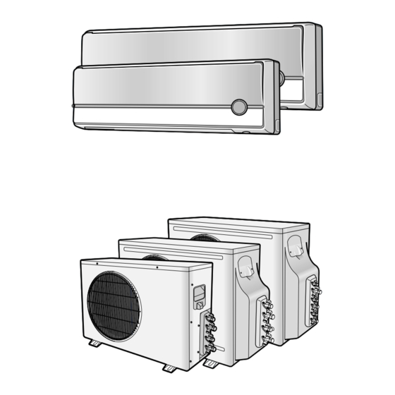
MULTI AIR CONDITIONER INDOOR UNIT OUTDOOR UNIT MH18AP1(P2)-09 MH18AP1(P2)X MH19AP1(P2)-07 MH19AP1(P2)X MH19AP1(P2)-12 MH24AP1(P2)-12 MH24AP1(P2)X MH26AP1(P2)-07 MH26AP1(P2)X MH26AP1(P2)-12 Manual SERVICE AIR CONDITIONER CONTENTS 11. Product Specifications 12. Operating Instructions & Technical Document 13. Disassembly and Reassembly 14. Refrigerating Cycle Diagram 15. Set Up the Model Option 16. -
Page 2: Product Specifications
1. Product Specifications 1-1 Table MH18AP1(P2) MH19AP1(P2) Model INDOOR UNIT OUTDOOR UNIT INDOOR UNIT OUTDOOR UNIT MH19AP1(P2)-07 MH18AP1(P2)-09 MH18AP1(P2)X MH19AP1(P2)X Item MH19AP1(P2)-12 Type WALL-MOUNTING MULTI SPLIT WALL-MOUNTING MULTI SPLIT Cooling/Heating 1 Unit(A) 2.65 / 2.78 2.05 / 2.25 1 Unit(B/C) 2.65 / 2.78... - Page 3 A,B-UNIT:CAPILLARY TUBE B,C-UNIT:ELEC.EXPANSION V/V Refrigerant to Change(R410A) A-UNIT:1,000g / B-UNIT:1,000g A-UNIT:910g / B-UNIT:1,290g 16(A-UNIT) Additional Refrigerant 16(A,B-UNIT) 21(B+C-UNIT) (Refrigerant must be added if the piping) RAC12128-9622 RAC12128-9622 Protection Device RAC12122-9622 Standard Conditions ISO R5151 STANDARD ISO R5151 STANDARD Samsung Electronics...
- Page 4 MEMO Samsung Electronics...
-
Page 5: Operating Instructions
After 30minutes, the air conditioner is reset automatically to the previous mode. Sleep button. The sleep timer can be used when you are cooling or heating your room to switch the air conditioner off automatically after a period of 6 hours. Samsung Electronics... - Page 6 After setting On Timer or Off Timer, press the button to set it completely. And press the button again to cancel On Timer or Off Timer set. Digital On/Off button. If you want to turn off the display during operation press the button. Samsung Electronics...
- Page 7 Room Temperature Operating Mode Temperature Setting heat exchanger temperature and accumulating time of Less than 21˚C Heat 24˚C approx. compressor's operation. 21˚C or above Cool 22˚C approx. Deice ends by sensing of the processing time by deice condition. Samsung Electronics...
- Page 8 In case of option data error 12. BUZZER SOUND : Whenever the On/Off button is pressed or whenever change occurs to the condition which is set up or select, the compulsory operation mode, buzzer is sounded "beep". Samsung Electronics...
-
Page 9: Technical Document
27/19 35/24 31.6 30.4 27/19 43/26 38.5 38.8 38.8 38.5 31.6 28.8 28.8 28.8 30.4 26.5 27.2 25.2 25.2 25.2 A-unit B-unit Outdoor Temperature (ßC) 9.52 9.52 8.73 8.73 A-unit 8.28 8.28 8.51 8.51 B-unit Outdoor Temperature (ßC) Samsung Electronics... - Page 10 25.0 27/19 27/20 26.8 24.4 Cooing 27/19 35/24 32.3 31.3 27/19 43/26 38.2 37.9 38.2 37.9 32.3 27.8 31.3 26.8 25.0 25.0 25.0 25 25 24.4 24.4 24.4 A-unit B-unit Outdoor Temperature (ßC) A-unit B-unit Outdoor Temperature (ßC) Samsung Electronics...
- Page 11 (27.8) (27.8) 27.8 27.5 25.69 25.69 25.7 25.5 23.85 23.85 23.9 23.8 23.5 21.5 19.5 20.2 17.5 15.5 A-unit B-unit 13.5 11.5 Outdoor Temperature (ßC) 6.84 6.84 (5.9) (5.9) 3.68 3.68 A-unit B-unit 3.72 3.72 Outdoor Temperature (ßC) Samsung Electronics...
- Page 12 19.6 Heating 20/15 29.0 25.7 31.5 29.0 29.5 27.4 27.5 25.5 23.93 23.93 23.9 25.7 23.5 23.8 21.5 19.5 19.6 17.5 A-unit 15.5 B-unit 13.5 11.5 Outdoor Temperature (ßC) (27.4) (27.4) (5.9) (5.9) A-unit B-unit Outdoor Temperature (ßC) Samsung Electronics...
- Page 13 B-unit A-unit B-unit 27/19 21/15 27.2 27.0 27/19 27/20 26.8 26.6 Cooing 27/19 35/24 31.8 31.6 27/19 43/26 38.4 37.6 38.4 37.6 31.8 31.6 27.2 26.8 27.0 26.6 A-unit B-unit Outdoor Temperature (ßC) A-unit B-unit Outdoor Temperature (ßC) Samsung Electronics...
- Page 14 B-unit A-unit B-unit 27/19 21/15 27.4 27.2 27/19 27/20 27.0 26.8 Cooing 27/19 35/24 32.0 31.8 27/19 43/26 38.6 37.8 38.6 37.8 32.0 31.8 27.4 27.0 27.2 26.8 A-unit B-unit Outdoor Temperature (ßC) A-unit B-unit Outdoor Temperature (ßC) Samsung Electronics...
- Page 15 Operating Instructions & Technical Document Heating(7.5m–Piping) High Pressure Low Pressure Indoor Outdoor (DB/WB) (DB) A-unit B-unit A-unit B-unit 20/15 –10 22.7 27.5 Heating 20/15 27.7 33.1 33.1 27.5 27.7 A-unit B-unit 22.7 Outdoor Temperature (ßC) A-unit B-unit Outdoor Temperature (ßC) Samsung Electronics...
- Page 16 Indoor Outdoor (DB/WB) (DB) A-unit B-unit A-unit (7.5m) B-unit (32.5m) 20/15 –10 21.3 26.7 Heating 20/15 26.3 32.3 36.5 32.3 31.5 26.7 26.5 26.3 21.5 21.3 16.5 A-unit B-unit 11.5 Outdoor Temperature (ßC) A-unit B-unit Outdoor Temperature (ßC) Samsung Electronics...
- Page 17 21/15 28.8 26.0 27/19 27/20 27.9 25.4 Cooing 27/19 35/24 31.1 30.1 27/19 43/26 38.0 38.0 38.0 38.0 31.1 28.75 28.75 28.8 27.9 30.1 26.0 25.4 25.4 25.4 A-unit B-unit Outdoor Temperature (ßC) A-unit B-unit Outdoor Temperature (ßC) Samsung Electronics...
- Page 18 26.0 27/19 27/20 26.9 24.4 Cooing 27/19 35/24 30.1 29.1 27/19 43/26 37.3 37.0 37.3 37.0 37 37 30.1 30.1 30.1 27.8 26.9 29.1 26.0 24.4 24.4 24.4 A-unit B-unit Outdoor Temperature (ßC) A-unit B-unit Outdoor Temperature (ßC) Samsung Electronics...
- Page 19 26.7 31.5 30.0 29.5 (28.4) (28.4) 28.4 27.5 26.7 24.9 25.5 (24.8) (24.8) 24.8 23.5 21.5 19.5 20.61 20.61 20.6 17.5 A-unit 15.5 B-unit 13.5 11.5 Outdoor Temperature (ßC) 6.85 6.85 (5.9) (5.9) A-unit B-unit Outdoor Temperature (ßC) Samsung Electronics...
- Page 20 B-unit 20/15 –10 23.9 19.6 Heating 20/15 29.0 25.7 31.5 29.0 29.5 27.4 27.5 25.7 25.5 23.91 23.91 23.9 23.5 23.8 21.5 19.6 19.5 17.5 A-unit 15.5 B-unit 13.5 11.5 Outdoor Temperature (ßC) A-unit B-unit Outdoor Temperature (ßC) Samsung Electronics...
- Page 21 38.0 43.0 39.5 39.0 38.0 35.0 32.2 31.0 31.3 27.3 27.1 27.0 25.46 25.46 25.5 25.06 25.06 25.1 23.0 A-unit 19.0 B-unit 15.0 Outdoor Temperature (ßC) 10.0 9.31 9.31 A-unit B-unit 6.77 6.77 6.64 6.64 Outdoor Temperature (ßC) Samsung Electronics...
- Page 22 32.9 29.57 29.57 29.6 31.0 32.40 32.40 32.4 28.6 29.32 29.32 29.3 27.0 28.1 23.0 A-unit 19.0 B-unit 15.0 Outdoor Temperature (ßC) 10.0 9.12 9.12 8.33 8.33 8.33 8.14 8.14 A-unit B-unit 7.62 7.62 7.62 Outdoor Temperature (ßC) Samsung Electronics...
- Page 23 (DB) A-unit B-unit A-unit B-unit 20/15 –10 20.0 19.3 Heating 20/15 24.8 24.7 20/15 28.0 27.2 28.0 27.2 24.8 24.7 A-unit B-unit 20.0 19.3 Outdoor Temperature (ßC) 6.38 6.38 (5.22) (5.22) 3.27 3.27 A-unit B-unit Outdoor Temperature (ßC) Samsung Electronics...
- Page 24 High Pressure Low Pressure Indoor Outdoor (DB/WB) (DB) A-unit B-unit A-unit B-unit 20/15 –10 19.7 19.0 Heating 20/15 24.4 24.3 20/15 27.7 25.5 27.7 24.4 25.5 24.3 19.7 A-unit B-unit 19.0 Outdoor Temperature (ßC) A-unit B-unit Outdoor Temperature (ßC) Samsung Electronics...
-
Page 25: Disassembly And Reassembly
6) Loosen one of the right screw and detach the Terminal Cover. 7) Detach the thermistor from the Front Grille. 8) Loosen 5 fixing screws of Front Grille. 9) Pull the lower left and right of discharge softly for the outside cover to be pulled out. Samsung Electronics... - Page 26 Power Cord) (Main PCB) 2) Detach the outdoor unit connection wire from the Terminal Block. 3) If pulling the main PCB up, it will be taken out. 1) Pull Tray Drain out from the Back Body. Tray Drain Samsung Electronics...
- Page 27 1) Loosen 2 fixing screws and detach the Fan Motor Motor Holder. & Cross Fan 2) Loosen 1 fixing screw of Fan Motor. (with a M3 wrench) 3) Detach the Fan Motor from the Fan. 4) Detach the Fan from the left Holder Bearing. Samsung Electronics...
- Page 28 * When you assemble the parts, check if the each parts and Component Electric Box are fixed firmly. <MH24AP1(P2)X/MH26AP1(P2)X> <MH18AP1(P2)X/MH19AP1(P2)X> 1) Detach the Nut Flange. Fan Motor (Turn to the clockwise) & 2) Disassemble the Propeller Fan. Propeller Fan <MH24AP1(P2)X/MH26AP1(P2)X> Samsung Electronics...
-
Page 29: Refrigerating Cycle Diagram
4. Refrigerating Cycle Diagram 4-1 MH18AP1(P2)X 3/8" A-Room 3/8" 3/8" ID1.3*650L 7.94mm sensor sensor Comp-A 1/4" 3/8" 3/8" 3/8" 3/8" B-Room 7.94mm ID1.3*650L sensor sensor Comp-B 1/4" 3/8" Samsung Electronics... - Page 30 4-2 MH19AP1(P2)X 3/8" A-Room 3/8" ID 1.3*800L 3/8" 7.94mm sensor sensor Comp-A 1/4" 3/8" 3/8" 3/8" 3/8" sensor 7.94mm 1/4" 1/4" ID1.3*550L 5/16" ¿4.76 B-Room Comp-B sensor ID 1.3*500L 1/4" 3/8" Samsung Electronics...
- Page 31 4-3 MH24AP1(P2)X 3/8" 3/8" 3/8" sensor ID 1.3*550 7.94mm A-Room sensor Comp-A 1/4" 3/8" 3/8" 3/8" 3/8" sensor 7.94mm sensor ID1.3*650 B-Room Comp-B 3/8" 1/4" Samsung Electronics...
- Page 32 4-4 MH26AP1(P2)X B-Room (MH26AP2-07) sensor A-Room (MH26AP2-12) sensor C-Room (MH26AP2-07) sensor ID1.5*700 sensor ID1.3*500 1/4"(7.5m) 3/8"(7.5m) ID1.3*650 Distributor 1/4"(7.5m) Elec.expansion valve 3/8"(7.5m) ID1.3*650 Comp-B/C 1/4"(7.5m) Comp-A sensor Elec.expansion valve 3/8"(7.5m) Samsung Electronics...
-
Page 33: Set Up The Model Option
. . . repeatedly. Push the button to set the display panel to Setting is not required if you must Every time you push the button, the display panel reads a value which has a default..repeatedly. Samsung Electronics... - Page 34 If all lamps of indoor unit are flickering, Plug out and plug in again and pressing ON/OFF key to retry. If the unit is not working properly or all lamps are continuously flickering after setting the option code, see if the correct option code is set up for it's model. Samsung Electronics...
- Page 35 Set up the Model Option Table of the option code MODEL OPTION CODE MH18AP1(P2)-09 024553-106340 MH19AP1(P2)-07 023553-10620c MH19AP1(P2)-12 067503-106362 MH24AP1(P2)-12 067533-106362 MH26AP1(P2)-07 023753-10420c MH26AP1(P2)-12 067553-104351 Samsung Electronics...
-
Page 36: Troubleshooting
The compressor stops intermittently in a The compressor stops intermittently or the fan speed of the COOL mode or DRY mode, and fan speed of the indoor unit decreases to prevent inside/outside air frozen indoor unit decreases. depending on the inside/outside air temperature. Samsung Electronics... -
Page 37: Checking And Testing Operations
ROOM NO 1(#51) 2(#52) A unit A unit B unit C unit 2. Apply the power to the outdoor unit. - Check the fuse (250V~, 5A) : The fuse is opened when the power line (L, N) is short. Samsung Electronics... - Page 38 Result: If all of three units display lamps are flickering, the connection wires and the room option connections are good. MH18–/MH19–/MH24– MH26– OUTDOOR UNIT OUTDOOR UNIT TEST OPERATING S/W-A S/W-B S/W-C TEST OPERATING A : PCB display A : PCB display B : Red LED B : Red LED C : PCB switch C : PCB switch Samsung Electronics...
- Page 39 Communication unit number display : C unit • During the test operation the unit under test is on and off every 0.25s. (In case of triple split multi air conditioner) High temperature of the A cond High temperature of the B cond Samsung Electronics...
- Page 40 Check the temperature sensor of A Outdoor unit sensor error(short/open) condenser pipe. Check the outdoor temperature sensor. Outdoor unit sensor error(short/open) Error in setting indoor unit's address & outdoor unit Check the indoor unit's address. communication error Samsung Electronics...
- Page 41 5. Check the operation is normal. Start up is over. MH18–/MH19–/MH24– MH26– OUTDOOR UNIT OUTDOOR UNIT TEST OPERATING S/W-A S/W-B S/W-C TEST OPERATING A : PCB display A : PCB display B : Red LED B : Red LED C : PCB switch C : PCB switch Samsung Electronics...
-
Page 42: Fault Diagnosis By Symptom
Check PCB pattern. Replace IC02 10ms Replace main PCB. Is voltage output terminal of PC814(PC02) normal? Are voltage at #23 and #24 of the micom normal? Replace resonator (X301) 250ns Replace PC814(PC02) Is operation normal? Replace micom Samsung Electronics... - Page 43 Replace the fuse (250V, 3.15A). receiving module? Replace of Ass'y display PCB Is the output voltage of electrostatic voltage KA7805 is out of order - replace regulator IC (KA7805) DC 4.5V ~ 5.5V? Replace the main PCB of indoor unit Samsung Electronics...
- Page 44 Check whether the output voltage of IC01 diode of power side (D101-D104) (KA7812) is DC 12V. and KA7812. Check whether the output voltage of IC02 Replace the IC02 (KA7805) (KA7805) is DC 5V. Replace the outdoor unit Ass'y main PCB. Samsung Electronics...
- Page 45 Replace the IC07(ULN2003A) and Is the pin #15 of IC07(ULN2003A) SS71(G3MB202PL or AQG22212) the old type? 120Hz Is the pin #17 of MICOM the Replace Q501(2SC2412K) old type? Replace the indoor unit PCB Ass'y due to the Micom defect. Samsung Electronics...
- Page 46 (3) Perform the comp ON/OFF control in the dry mode. (4) When it is under the operation of anti-freezing, overload protection, defrost operation, it may be Low, high or Off. (5) Hi = High speed, Low = Low speed Samsung Electronics...
- Page 47 Voltage at pin #26~#29 of micom (IC04) change? Micom (IC04) is faulty. (Squarewave) Driver IC06(ULN2003A) or Voltage at pin #10~#12 of IC06, #16 of IC07(ULN2003A) IC07(ULN2003A) is faulty. change? (Squarewave) UP/DOWN louver motor is faulty. Samsung Electronics...
- Page 48 Voltage at pin #30 of Remocon Micom change? Q601(C4375Y) or Q602(C1623Y) is faulty. Voltage at collector of Q601 or Q602 change? IR LED(CL-1L5EU) is faulty. Voltage at pin #15 of micom (IC04) change (INDOOR UNIT)? Receiver module is faulty. Micom (IC04) is faulty. Samsung Electronics...
- Page 49 (2) During the heating operation put the 4-Way valve A(B) on. (3) The changeover of heating to cooling : put the 4-Way valve off immediately (in case of B and C room). (4) The changeover of cooling to heating : it is on after 170 seconds delay. Samsung Electronics...
- Page 50 (2) Comp B : Comp on /off control in accordance with the B(C) room during the heating and cooling indoor unit operation Comp A(B) power measuring terminal (1) Comp A measuring ; RY73 (4) ↔ RY72 (4) RY73 (2) Comp B measuring ; RY71 (4) ↔ RY72 (4) (3) Power input ; RY72 (3) ↔ RY73(3) RY71 RY72 Samsung Electronics...
-
Page 51: Pcb Inspection
6-4-2 Procedure The parts should be replaced in the following procedure. Check for any faulty part. Detach the faulty part. Replace it with a new part. Check the operation of the new part. The repair is completed. Samsung Electronics... - Page 52 • Indoor unit fan motor is faulty. when RMC switch above 180V~ pushed. 2) Indoor unit fan motor does not operate. • Poor connection of indoor fan motor and 1. [FAN] mode connector of RPM sensing (CN44) 2. Fan speed [Hi] 3. Continuously operation Samsung Electronics...
-
Page 53: Exploded Views And Parts List
7. Exploded Views and Parts List 7-1 Indoor Unit 15-1 15-6 15-2 15-4 15-3 15-5 1-1-2 1-1-3 1-1-1 1-1-4 1-1-5 1-1-6 You can search for the updated part code number through the ITSELF. URL : http://itself.sec.samsung.co.kr Samsung Electronics... -
Page 54: Parts List
Exploded Views and Parts List Parts List Q'TY Code No. Description Specification MH18AP1(P2)-09 MH19AP1(P2)-12 MH26AP1(P2)-07 MH26AP1(P2)-12 MH19AP1(P2)-07 MH24AP1(P2)-12 DB92-00558A ASS'Y PANEL FRONT TOTAL ASS'Y DB92-00561A ASS'Y PANEL FRONT TOTAL ASS'Y DB92-00557A ASS'Y PANEL FRONT SUB P ASS'Y DB92-00560A ASS'Y PANEL FRONT SUB P... - Page 55 7-2 Outdoor Unit MH18AP1(P2)X / MH19AP1(P2)X 8(8-1~8-7) 11(11-1~11-5) 7(7-1) Samsung Electronics...
- Page 56 DB60-30028A NUT-WASHER 11-3 DB60-30018A NUT-FLANGE 11-4 DB63-10165D COVER TERMINAL PBT,2.5 11-5 DB35-00015W PROTECTOR O/L RAC12131-9622 DB35-00015T PROTECTOR O/L RAC12126-9622 DB35-00015V PROTECTOR O/L RAC12128-9622 DB96-01717F ASS'Y-COND UNIT ASS'Y DB96-01717G ASS'Y-COND UNIT ASS'Y DB32-00025C THERMISTOR-OUT ASS'Y ASS'Y DB63-00343A GUARD-COND SC-90073T Samsung Electronics...
- Page 57 Exploded Views and Parts List MH24AP1(P2)X (8-1~8-6) (1-1) (11-1~11-5) (5-1~5-2) Samsung Electronics...
- Page 58 ASS'Y PARTITION ASS'Y DB90-00569A ASS'Y CABI-UPPER ASS'Y G8C124JU1EL ROTARY COMPRESSOR G8C124JU1EL 11-1 DB73-00067A GROMMET ISOLATOR 11-2 DB60-30028A NUT-WASHER 11-3 DB60-30018A NUT-FLANGE 11-4 DB63-10165D COVER TERMINAL PBT,2.5 11-5 DB35-00015V PROTECTOR O/L RAC12128-9622 DB96-03285A ASS'Y-COND UNIT ASS'Y DB63-30027C GUARD COND SC-90073T Samsung Electronics...
- Page 59 Exploded Views and Parts List MH26AP1(P2)X 8-6~8-7 (7-2-1,7-2-2) (7-5-1,7-5-2) 11-4 11-3 11-5 11-6 11-2 (7-3-1,7-3-2) 11-1 Samsung Electronics...
- Page 60 11-1 DB73-00067A GROMMET ISOLATOR 11-2 DB60-30028A NUT-WASHER 11-3 DB60-30018A NUT-FLANGE 11-4 DB63-10165D COVER TERMINAL PBT,2.5 11-5 DB35-00015V PROTECTOR O/L RAC12128-9622 11-6 DB35-00015P PROTECTOR O/L RAC12122-9622 DB96-03365A ASS'Y-COND UNIT ASS'Y DB32-00025D THERMISTOR-OUT ASS'Y ASS'Y DB37-00003A CONNECTOR WIRE MOTOR ASS'Y Samsung Electronics...
- Page 61 7-3 Ass'y Control In (Indoor Unit) MH18AP1(P2)-09, MH19AP1(P2)-07 : DB93-02567A MH19AP1(P2)-12, MH24AP1(P2)-12 : DB93-02568A MH26AP1(P2)-07 : DB93-02567B MH26AP1(P2)-12 : DB93-02568B Samsung Electronics...
- Page 62 Exploded Views and Parts List Parts List Q'TY Code No. Description Specification MH18AP1(P2)-09 MH19AP1(P2)-12 MH26AP1(P2)-07 MH26AP1(P2)-12 MH19AP1(P2)-07 MH24AP1(P2)-12 DB61-01127A CASE-CONTROL AC DB61-01631A CASE-CONTROL AC DB93-02416A ASS'Y MAIN PCB ASS'Y DB93-02416B ASS'Y MAIN PCB ASS'Y DB93-01368G ASS'Y S/W & DISPLAY PCB...
-
Page 63: Pcb Diagram
8. PCB Diagram 8-1 MAIN PCB(Indoor Unit) Samsung Electronics... - Page 64 PCB Diagram BOTTOM Samsung Electronics...
- Page 65 R-CHIP 100Kohm,5%,1/8W,TP,2012 R201, R202, R203, R204 R-CHIP 100Kohm,5%,1/4W,TP,3216 R101 R-CHIP 100ohm,5%,1/8W,TP,2012 R205,R303,R505,R601 R-CHIP 10Kohm,5%,1/8W,TP,2012 R603,R901~R904 R206,R207,R211,R301 R-CHIP 1Kohm,5%,1/8W,TP,2012 R501,R502,R506,R602 R604,R610 R102 R-CHIP 2.2Kohm,5%,1/8W,TP,2012 R402,R404 R-CHIP 330ohm,5%,1/8W,TP,2012 R504,R606,R703 R-CHIP 4.7Kohm,5%,1/8W,TP,2012 R105,R302,R607,R608 R-CHIP 470ohm,5%,1/8W,TP,2012 R511,R512 R-CHIP 47Kohm,5%,1/8W,TP,2012 R401,R403 R-CHIP 6.8Kohm,1%,1/8W,TP,2012 Samsung Electronics...
- Page 66 FUSE-BLOCK 500V,-,100M CN71 CONNECTOR-HEADER 1WALL,3P,1R,7.92mm,STRAIGHT,SN,BL CN72 CONNECTOR-HEADER 1WALL,3P,1R,7.92mm,STRAIGHT,SN,WH CN44 CONNECTOR-HEADER BOX,3P,1R,2.5mm,STRAIGHT,SN CN63 CONNECTOR-HEADER BOX,5P,1R,2.5mm,STRAIGHT,SN CN91 CONNECTOR-HEADER BOX,14P,1R,2mm,STRAIGHT,SN CN45 CONNECTOR-HEADER BOX,3P,1R,2mm,STRAIGHT,SN CN41 CONNECTOR-HEADER BOX,4P,1R,2mm,STRAIGHT,SN CN61 CONNECTOR-HEADER BOX,5P,1R,2mm,STRAIGHT,SN IC04 IC MICOM MB89538APF-101,MB89538APF-101,64P,+5V,10M ST11 TRANS SWITCHING TRANS SWITCHING;-,JT1916-09,-,310V,FERRITE,-,EI191 FT71 COIL,CHOKE LS404190M,AS-S660,19MH,+50,-30%,-,300Mohm,2A,-,-,- Samsung Electronics...
- Page 67 8-2 MAIN PCB(Outdoor Unit) 18K/19K/24K Samsung Electronics...
- Page 68 PCB Diagram Samsung Electronics...
- Page 69 D101~D104,D701 DIODE-RECT 1N4007 D401~D408 DIODE-SWITCHING 1N4148 ZD71 ZENNER-DIODE UZP30P 30V SEG1 LED-DISPLAY SSD-A3202GMT-S GRN SEG1 HOLDER-SEVEN LED1 LED-LAMP RED LTL-4213 FT71 FILTER NOISE MD250V 1.6A 6mH X101 PERSONATOR-CERAMIC 10MHz Q901,Q902 TRANSISTOR KSR2002 Q301,Q302 TRANSISTOR KSR1002 S/W-A,S/W-B,S/W-C SWITCH-TACT KPT-1115V Samsung Electronics...
- Page 70 CONNECTOR WAFER YW396-03AV WHT CN76 CONNECTOR WAFER YW396-03AV RED CN91,CN92 CONNECTOR WAFER YW250-14 WHT CN61 CONNECTOR WAFER YW250-05 WHT CN62 CONNECTOR WAFER YW250-05 BLU GT01 CONNECTOR-TERMINAL GP88191-2 IC01 SCREW-PH M3 * G FeFzY IC01 HEATSI-PH AL H25 PCB-OUT FR-1 Samsung Electronics...
- Page 71 8-3 ASS'Y DISPLAY PCB : DB93-01368G Parts List Description Specification Q'TY Remark ASS'Y LED MODULE PCB-DISPLAY FR-1 T1.6 TACT SWITCH KPT-1105A RESISTOR 200ohm, 2W RESISTOR 100ohm, 2W CONNECTOR WIRE Samsung Electronics...
- Page 72 FR1 T1.6 CONNECTOR-HEADER BOX, 3P, 1R, 2mm, ANGLE, SN C-CERAMIC, MLC-AXIAL 1nF, 10%, 50V, Y5P, TP, 1.9 x 3.5, - DIODE-SWITCHING 1N4148, 100V, 200mA, DO-35, TP C-CERAMIC, MLC-AXIAL 100nF, +80-20%, 50V, Y5V, TP, 3.5 x 1 MODULE FRP4021H7 Samsung Electronics...
- Page 73 MEMO Samsung Electronics...
-
Page 74: Wiring Diagram
9. Wiring Diagram 9-1 Indoor Unit Code No : DB98-15806A This Document can not be used without Samsung's authorization. Samsung Electronics... - Page 75 9-2 Outdoor Unit MH18AP1(P2)X/MH19AP1(P2)X/MH24AP1(P2)X Code No : DB68-20814A This Document can not be used without Samsung's authorization. Samsung Electronics...
- Page 76 Wiring Diagram MH26AP1(P2)X Code No : DB68-01437A This Document can not be used without Samsung's authorization. Samsung Electronics...
- Page 77 MEMO Samsung Electronics...
-
Page 78: Schematic Diagram
10. Schematic Diagram 10-1 Indoor Unit This Document can not be used without Samsung's authorization. Samsung Electronics... - Page 79 10-2 Outdoor Unit MH18AP1(P2)X/MH19AP1(P2)X/MH24AP1(P2)X This Document can not be used without Samsung's authorization. Samsung Electronics...
- Page 80 Schematic Diagram MH26AP1(P2)X This Document can not be used without Samsung's authorization. Samsung Electronics...
- Page 81 MEMO Samsung Electronics...
- Page 82 ELECTRONICS © Samsung Electronics Co., Ltd. Feb. 2004. This Service Manual is a property of Samsung Electronics Co., Ltd. Any unauthorized use of Manual can be punished under applicable Printed in Korea. International and/or domestic law. Code No. DB98-16045A(4)
Need help?
Do you have a question about the MH18AP1(P2)-09 and is the answer not in the manual?
Questions and answers