
Related Manuals for CS SR50A

Summary of Contents for CS SR50A
- Page 1 SR50A, SR50A-316SS, and SR50AH Sonic Ranging Sensors Revision: 10/16 C o p y r i g h t © 2 0 0 7 - 2 0 1 6 C a m p b e l l S c i e n t i f i c ,...
-
Page 3: Limited Warranty
Limited Warranty “Products manufactured by CSI are warranted by CSI to be free from defects in materials and workmanship under normal use and service for twelve months from the date of shipment unless otherwise specified in the corresponding product manual. (Product manuals are available for review online at www.campbellsci.com.) Products not manufactured by CSI, but that are resold by CSI, are warranted only to the limits extended by the original manufacturer. - Page 4 Assistance Products may not be returned without prior authorization. The following contact information is for US and international customers residing in countries served by Campbell Scientific, Inc. directly. Affiliate companies handle repairs for customers within their territories. Please visit www.campbellsci.com determine which Campbell Scientific company serves your country.
- Page 5 Safety DANGER — MANY HAZARDS ARE ASSOCIATED WITH INSTALLING, USING, MAINTAINING, AND WORKING ON OR AROUND TRIPODS, TOWERS, AND ANY ATTACHMENTS TO TRIPODS AND TOWERS SUCH AS SENSORS, CROSSARMS, ENCLOSURES, ANTENNAS, ETC. FAILURE TO PROPERLY AND COMPLETELY ASSEMBLE, INSTALL, OPERATE, USE, AND MAINTAIN TRIPODS, TOWERS, AND ATTACHMENTS, AND FAILURE TO HEED WARNINGS, INCREASES THE RISK OF DEATH, ACCIDENT, SERIOUS INJURY, PROPERTY DAMAGE, AND PRODUCT FAILURE.
-
Page 7: Table Of Contents
Table of Contents PDF viewers: These page numbers refer to the printed version of this document. Use the PDF reader bookmarks tab for links to specific sections. 1. Introduction ..............1 2. Precautions ..............1 3. Initial Inspection ............1 4. - Page 8 Configure Tera Term for Serial 9600 BPS Communication .... E-1 Firmware Update ................E-5 E.2.1 Configure Tera Term to Send SR50A/T Firmware Update ..E-5 E.2.2 Sending New Firmware to a SR50A/T Sensor ......E-6 F. SR50AH Heater Operation ........F-1 Heater Specifications ................
- Page 9 Beam Angle Clearance ................. 7 7-2. Distance from Edge of Transducer Housing to Grill ......8 7-3. SR50A Mounted to a Crossarm via the 19517 Mounting Kit ....9 7-4. Another Angle of the 19517 Mounting Kit .......... 9 7-5.
- Page 10 Table of Contents B-4. CR1000 Programming Example Using an MD485 and SC110 9-pin Male Connector ..............B-10 B-5. CR6 RS-485 Programming Example ..........B-13 B-6. CR1000 Heater Program Example ..........B-16 B-7. CR6 Heater Program Example ............B-19...
-
Page 11: Introduction
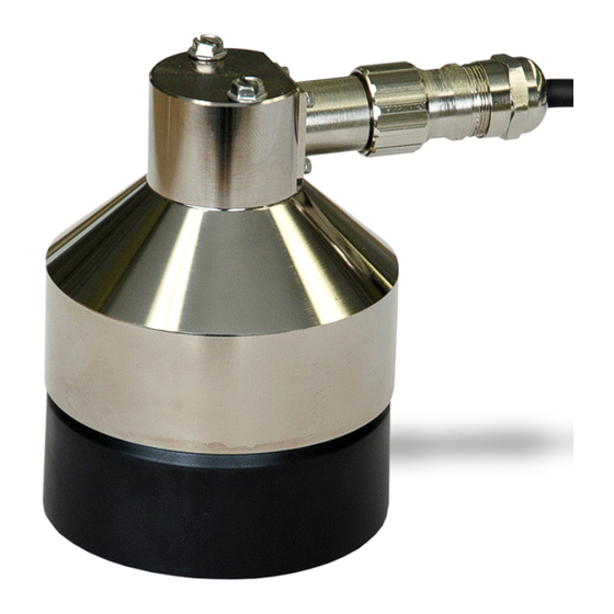
SR50A-Series Sonic Ranging Sensor Introduction The SR50A, SR50A-316SS, and SR50AH are sonic ranging sensors that provide a non-contact method for determining snow or water depth. They determine depth by emitting an ultrasonic pulse and then measuring the elapsed time between the emission and return of the pulse. An air temperature measurement is required to correct for variations of the speed of sound in air. -
Page 12: Quickstart
SR50A-Series Sonic Ranging Sensors QuickStart Short Cut is an easy way to program your datalogger to measure the SR50A and assign datalogger wiring terminals. Short Cut is available as a download on and the ResourceDVD. It is included in installations of www.campbellsci.com... - Page 13 Data defaults to meters, which can be changed by clicking the Unit of measure box and selecting cm, ft, or in. Enter the Distance to base, which is the distance from the SR50A’s wire mesh face to the ground. SDI-12 Address defaults to 0. Enter the correct SDI-12 Address for the SR50A if it has been changed from the factory-set default value.
-
Page 14: Overview
Overview The SR50A-series sensors measure the distance from the sensor to a target. They determine the distance to a target by sending out ultrasonic pulses (50 kHz) and listening for the returning echoes that are reflected from the target. -
Page 15: Specifications
SR50A. The SR50A is factory configured as an SDI-12 sensor (address 0) because Campbell dataloggers typically use the SDI-12 format. To use the RS-232 or RS-485 format, three jumpers inside the SR50A need to be moved (Section 9.1, Disassembly/Assembly Procedures , and Appendix C, (p. - Page 16 SR50A-Series Sonic Ranging Sensors Accuracy: ±1 cm (±0.4 in) or 0.4% of distance to target, whichever is greater. Accuracy specification excludes errors in the temperature compensation. An external temperature compensation is required for the SR50A. Resolution: 0.25 mm (0.01 in) Required Beam Angle Clearance: 30°...
-
Page 17: Installation
FIGURE 7-1. Beam Angle Clearance 7.1.2 Mounting Height Mount the SR50A so that the face of the transducer is at least 50 cm (19.7 in) away from the target. However, mounting the sensor too far from the target can increase the absolute error increases. For example, if your sensor is measuring... -
Page 18: Reference Point
FIGURE 7-2. Distance from Edge of Transducer Housing to Grill 7.1.3 Mounting Options To achieve an unobstructed view for the SR50A’s beam, the SR50A is typically mounted to a tripod mast, tower leg, or user-supplied pole using the CM206 6-ft crossarm or a pipe with a 1-inch to 1.75-inch outer diameter. The 19517 mounting kit attaches directly to the crossarm or pipe. -
Page 19: Sr50A Mounted To A Crossarm Via The 19517 Mounting Kit
SR50A-Series Sonic Ranging Sensors FIGURE 7-3. SR50A Mounted to a Crossarm via the 19517 Mounting FIGURE 7-4. Another Angle of the 19517 Mounting Kit FIGURE 7-5. SR50A Mounted to a 19484 Mounting Stem... -
Page 20: Sdi-12 Wiring
SR50A-Series Sonic Ranging Sensors FIGURE 7-6. SR50A-316SS Mounted to a Crossarm with the 19484 and Nu-Rail Fitting SDI-12 Wiring Power down your system before wiring the SR50A. Never CAUTION operate the sensor with the shield wire disconnected. The shield wire plays an important role in noise emissions and susceptibility as well as transient protection. -
Page 21: Sdi12Recorder() Instruction
The closest object to the sensor will be detected if it is within this field of view. Unwanted objects must be outside the field of view. If a target is in motion, the SR50A may reject a reading if the target distance changes at a rate of 4 centimeters per second or more. -
Page 22: Quality Numbers
1 second due to the long communication times associated with the 1200 bps data rate. If the SR50A rejects a reading or does not detect a target, zero will be output for distance to target or –999 for depth values. -
Page 23: Sdi-12 Measurements
SR50A-Series Sonic Ranging Sensors SDI-12 Measurements 8.3.1 SDI-12 Addresses The SR50A can be set to one of ten addresses (0 to 9) which allows up to ten sensors to be connected to a single digital I/O channel (control port) of an SDI-12 datalogger. - Page 24 (5 digits) Address Query aAb! Change Address command b is the new address aXM;D.DDD! Set the distance to ground parameter in the SR50A. The Extended distance must be in meters with no more than three Address is returned command decimal places.
-
Page 25: Maintenance And Troubleshooting
SR50A-Series Sonic Ranging Sensors Maintenance and Troubleshooting The SR50A’s electrostatic transducer requires equal pressure on both sides. Vent holes in the transducer housing are used to equalize pressure. Desiccant (pn 4091) placed inside the transducer housing helps prevent condensing humidity. Regularly inspect the desiccant and, if required, replace it. Desiccant capable of absorbing moisture is blue. -
Page 26: Remove Six Screws From The Transducer Housing
SR50A-Series Sonic Ranging Sensors FIGURE 9-2. Remove Six Screws from the Transducer Housing FIGURE 9-3. Remove Transducer Housing and Disconnect Wires... -
Page 27: Location Of Desiccant In Transducer Housing Assembly
SR50A-Series Sonic Ranging Sensors FIGURE 9-4. Location of Desiccant in Transducer Housing Assembly FIGURE 9-5. Remove and Replace Desiccant... -
Page 28: Data Interpretation And Filtering
9.2.2 Data Filtering There are scenarios where the SR50A can produce values with higher than expected errors. For example, in very low density snow, very little echo is returned back to the sensor. The increase in echo quality numbers is an indication of the weak signals. - Page 29 SR50A-Series Sonic Ranging Sensors prone to the occasional erroneous reading from flying debris, drifting snow, or mounting hardware just outside the beam angle. The reason not to average values is that occasionally a number with a very high error value is produced, skewing the average. The value should be ignored and not averaged.
- Page 30 SR50A-Series Sonic Ranging Sensors...
-
Page 31: Importing Short Cut Code Into Crbasic Editor
Appendix A. Importing Short Cut Code Into CRBasic Editor This tutorial shows the following: How to import a Short Cut program into a program editor for • additional refinement • How to import a wiring diagram from Short Cut into the comments of a custom program Short Cut creates files, which can be imported into CRBasic Editor. -
Page 33: Example Programs
'CR1000 'This program contains a number of features not found in Short Cut. 'The initial distance value from the SR50A head to the ground is 'measured by setting the flag SR50A_MID to TRUE. Set this flag after 'installing the SR50A in the field. Setting this flag will initiate 'a measurement cycle and the resulting value stored as the initial 'distance. - Page 34 Alias SR50A_Raw(2) = RawQ : Units RawQ = unitless 'Quality number. 'Array to hold 11 SR50A measurements composed of a distance and 'quality number. Public SR50A(11,2) 'Sorted array of 11 SR50A measurements composed of a distance and 'quality number. Measurements are sorted by the distance value from 'smallest to largest.
-
Page 35: Cr6 Sdi-12 Program
If TimeIntoInterval (58,60,Min) Then SR50ACtrl = True EndIf 'Set this flag to true to get the initial distance from the SR50A 'to the ground. SR50A_MID Then SR50ACtrl = True 'Logic to make 11 snow depth measurements, sort them, and store 'the corrected values. - Page 36 PnlTmp_C : Units PnlTmp_C = °C 'CR6 panel temperature Public AirTempC : Units AirTempC = °C 'Air temperature 'Array to hold 11 SR50A measurements composed of a distance and 'quality number. Public SR50A(11,2) Public SR50A_Raw(2) Alias SR50A_Raw(1) = DT Units = meters 'Distance from the SR50A.
- Page 37 If TimeIntoInterval (13,15,Min) Then SR50ACtrl = True EndIf 'Set this flag to true to get the initial distance from the SR50A 'to the ground. SR50A_MID Then SR50ACtrl = True 'Logic to make 11 snow depth measurements, sort them, and store 'the corrected values.
-
Page 38: Rs-232 Example Programs
'CR1000 Series Datalogger 'This program contains a number of features not found in Short Cut. 'The initial distance value from the SR50A head to the ground is 'measured by setting the flag SR50A_MID to TRUE. Set this flag after 'installing the SR50A in the field. Setting this flag will initiate 'a measurement cycle and the resulting value stored as the initial 'distance. - Page 39 Alias ParseVals(5)=Chcksum Units Chcksum = value 'Array to hold 11 SR50A measurements composed of a distance and 'quality number. Public SR50A(11,2) 'Sorted array of 11 SR50A measurements composed of a distance and 'quality number. Measurements are sorted by the distance value from 'smallest to largest.
- Page 40 'Automated snow depth measurement. Must occur two minutes before 'actual storage time to get 11 measurements completed. If TimeIntoInterval (58,60,Min) Then SR50ACtrl = True EndIf 'Set this flag to true to get the initial distance from the SR50A 'to the ground. SR50A_MID Then SR50ACtrl = True SR50ACtrl Then 'Transmit serial command "p33<CR>"...
-
Page 41: Rs-485 Example Programs
B.3.1 CR1000 Programming Example Using an MD485 and SC110 9-pin Male Connector For this example, an MD485 is used to convert the SR50A RS-485 signals to RS-232. A SC110 9-pin male connector cable is used to free up the RS-232 port on the datalogger. -
Page 42: Sr50A (Configured For Md485) Wiring To Md485 (9-Pin Connector Plugged Into Md485 Rs-232 Port
'Program: SR50A_RS485_Port_C1-C2.CR1 'This program contains a number of features not found in Short Cut. 'The initial distance value from the SR50A head to the ground is 'measured by setting the flag SR50A_MID to TRUE. Set this flag after 'installing the SR50A in the field. Setting this flag will initiate 'a measurement cycle and the resulting value stored as the initial 'distance. - Page 43 Alias ParseVals(5)=Chcksum Units Chcksum = value 'Array to hold 11 SR50A measurements composed of a distance and 'quality number. Public SR50A(11,2) 'Sorted array of 11 SR50A measurements composed of a distance and 'quality number. Measurements are sorted by the distance value from 'smallest to largest.
- Page 44 'Automated snow depth measurement. Must occur two minutes before 'actual storage time to get 11 measurements completed. If TimeIntoInterval (58,60,Min) Then SR50ACtrl = True EndIf 'Set this flag to true to get the initial distance from the SR50A 'to the ground. SR50A_MID Then SR50ACtrl = True SR50ACtrl Then 'Transmit serial command "p33<CR>"...
-
Page 45: Cr6 Rs-485 Programming Example
'CR6 Series Datalogger 'This program contains a number of features not found in Short Cut. 'The initial distance value from the SR50A head to the ground is 'measured by setting the flag SR50A_MID to TRUE. Set this flag after 'installing the SR50A in the field. Setting this flag will initiate 'a measurement cycle and the resulting value stored as the initial 'distance. - Page 46 Alias ParseVals(5)=Chcksum Units Chcksum = value 'Array to hold 11 SR50A measurements composed of a distance and 'quality number. Public SR50A(11,2) 'Sorted array of 11 SR50A measurements composed of a distance and 'quality number. Measurements are sorted by the distance value from 'smallest to largest.
- Page 47 'Automated snow depth measurement. Must occur two minutes before 'actual storage time to get 11 measurements completed. If TimeIntoInterval (58,60,Min) Then SR50ACtrl = True EndIf 'Set this flag to true to get the initial distance from the SR50A 'to the ground. SR50A_MID Then SR50ACtrl = True SR50ACtrl Then 'Transmit serial command "p33<CR>"...
-
Page 48: Heater Program Examples
'CR1000 'This program contains a number of features not found in Short Cut. 'The initial distance value from the SR50A head to the ground is 'measured by setting the flag SR50A_MID to TRUE. Set this flag after 'installing the SR50A in the field. Setting this flag will initiate 'a measurement cycle and the resulting value stored as the initial 'distance. - Page 49 Alias SR50A_Raw(2) = RawQ : Units RawQ = unitless 'Quality number. 'Array to hold 11 SR50A measurements composed of a distance and 'quality number. Public SR50A(11,2) 'Sorted array of 11 SR50A measurements composed of a distance and 'quality number. Measurements are sorted by the distance value from 'smallest to largest.
- Page 50 If TimeIntoInterval (58,60,Min) Then SR50ACtrl = True EndIf 'Set this flag to true to get the initial distance from the SR50A 'to the ground. SR50A_MID Then SR50ACtrl = True 'Logic to make 11 snow depth measurements, sort them, and store 'the corrected values.
-
Page 51: B-7. Cr6 Heater Program Example
'CR6 'This program contains a number of features not found in Short Cut. 'The initial distance value from the SR50A head to the ground is 'measured by setting the flag SR50A_MID to TRUE. Set this flag after 'installing the SR50A in the field. Setting this flag will initiate 'a measurement cycle and the resulting value stored as the initial 'distance. - Page 52 If TimeIntoInterval (13,15,Min) Then SR50ACtrl = True EndIf 'Set this flag to true to get the initial distance from the SR50A 'to the ground. SR50A_MID Then SR50ACtrl = True 'Logic to make 11 snow depth measurements, sort them, and store 'the corrected values.
- Page 53 Appendix B. Example Programs CallTable Daily CallTable Hour NextScan EndProg B-21...
- Page 54 Appendix B. Example Programs B-22...
-
Page 55: Jumper Settings
Never install more than three jumpers and never mix the jumpers among the SDI-12, RS-232 or RS-485 locations. The other jumper located on the SR50A places the sensor in either the normal operation mode or in the program update mode. The program mode is only used for updating the internal firmware of the sensor. -
Page 57: D. Rs-232 And Rs-485 Operation
D.1 RS-232 Operation The SR50A sensor comes from the factory with the internal jumpers set to SDI-12 mode. To use the SR50A in the RS-232 mode of operation, the jumpers need to be set as outlined in Appendix C, Jumper Settings . -
Page 58: Rs-485 Operation
D.2 RS-485 Operation The SR50A sensor comes from the factory with the internal jumpers set to SDI-12 mode. To use the SR50A in the RS-485 mode of operation, the jumpers need to be set as outlined in Appendix C, Jumper Settings . -
Page 59: Connections For Rs-485 Mode
Appendix D. RS-232 and RS-485 Operation sensors that require lead lengths that exceed the limits of either RS-232 or SDI-12 communications. The SR50A can be connected directly the RS-485 port on the CR6 datalogger. D.2.1 RS-485 Wiring Using a MD485 TABLE... -
Page 60: Rs-485 Wiring To A Cr6 Datalogger
Appendix D. RS-232 and RS-485 Operation D.3 RS-485 Wiring to a CR6 Datalogger The SR50A is a half-duplex device and can only be used on the COM1 (C1 and C2) terminal blocks. TABLE D-4. Connections for CR6 RS-485 Mode Color... - Page 61 To enter Setup mode, type “setup” in the terminal window and press the Enter key. The word “setup” and all options in the setup menu are not case sensitive. The SR50A should respond with the setup menu shown in FIGURE D-4. FIGURE D-4. SR50A Setup Menu...
-
Page 62: Baud Rate Setting
(19200 or 38400 bps) may be used where faster communications are required. The quiescent current draw for the SR50A in serial mode is normally 1.25 mA for baud rates of 9600 or less. The current draw increases to 1.5 and 2.25 mA... -
Page 63: Address
Appendix D. RS-232 and RS-485 Operation It is possible to download a firmware update to the SR50A via the RS-232 or RS-485 communication interface. Higher baud rates may be desirable to speed up this process. It may take up to 30 minutes using a speed of 1200 bps, 7 minutes using 9600 bps, or 3 minutes using 38400 bps. -
Page 64: Distance To Target Or Depth
To obtain a valid snow depth value the parameter distance to ground must be entered in. The SR50AT will compensate the readings for temperature. Do not use this option on the SR50A sensor unless the SR50A is sent valid temperature reading via the Temperature Input command. D.4.5 Distance to Ground A valid distance to ground must be entered when the SR50A is configured to output snow depth values. -
Page 65: Output Unit
Appendix D. RS-232 and RS-485 Operation D.4.8 Output Unit The SR50A always outputs the distance to the target. The units for the distance value can be set to any of the following values: • Meters • Centimeters • Millimeters •... -
Page 66: Temperature Input Command
“i33<CR>” – information command with factory address of 33 D.5.4 Temperature Input Command The temperature input command is used to send the SR50A version of the sensor a temperature value that is to be used for temperature compensation. The value sent must be in degrees Celsius and should not exceed eight characters. - Page 67 152 to 600, where 600 is the poorest quality. TT.TT This setting must be set to Off. The SR50A will output a –999.00 if the Temperature Output option is set to ON. VVVVV This is the diagnostic output value. Each digit represents a pass or a fail on a diagnostic test.
-
Page 68: Information Message Output
Appendix D. RS-232 and RS-485 Operation D.6.2 Information Message Output The measurement output string for the SR50A is as follows: <STX>aa;SSSSS;H.H;F.F;BBBBB;WWWWW<CR><LF><ETX> <STX> is the hex character 0x02 (2 in decimal) These two characters are the serial address of the sensor. The default is 33. -
Page 69: Tera Term Quickstart
Click on the radio button next to Serial. Click on the down arrow to the far right of Port and pick the COM port you are using to communication with the SR50A/T. NOTE COM port 4 is used in the examples in this section. Your COM port may be different. -
Page 70: E-3. Terminal Configuration
FIGURE E-2. Setup Selections Select Terminal from the drop-down menu list in Setup. The SR50A/T does not echo characters sent to it. To see what you’re typing, Local Echo needs to be switched on by checking the box next to Local Echo (FIGURE E-3). -
Page 71: E-4. Windows Setup Changes
Appendix E. Tera Term QuickStart Select Window from the drop-down menu list in Setup. Change the title in the Window setup to SR50A 9600 Baud. The title is displayed at the top of the terminal session screen. By default, Tera Term works with white characters on a black background, but can be changed to black characters on a white background. -
Page 72: Configuring The Serial Port
Appendix E. Tera Term QuickStart Select Serial port from the drop-down list in Setup. Change the port to reflect what you will be using to work with the SR50A/T. Leave the other settings at their default values. Click the OK button when finished (FIGURE E-6). -
Page 73: Firmware Update
Configure Tera Term for Serial 9600 BPS Communication (p. E-1) Select Window from the drop-down menu list in Setup and change the title to SR50A/T Firmware Download. The title is displayed at the top of the terminal session screen. Configure the serial port as follows (FIGURE E-8). -
Page 74: Sending New Firmware To A Sr50A/T Sensor
SR50A_May_29_2007_V_1_3.TXT will be sent to a SR50AT. This firmware update is used for either the SR50A or SR50AT. To send a firmware update to the SR50A/T, the jumpers must be configured for RS-232 operation and the jumper moved from RUN to PROG. See FIGURE below. - Page 75 PROG (program) position. Connect to the DB-9 connector on the SR50A/T PC board. Connect the cable back to the SR50A/T. The cable should be providing the SR50A/T with power. When power is reestablished, you will see a green LED light up close by the RUN/PROG jumper.
- Page 76 You will see the following screen indicating that the transfer process is occurring in Tera Term. Directly above the Send File window, you will see the lines of code being sent to the SR50A/T. Do not click on any of the buttons in the Send File window. The window will automatically disappear after the file has been sent.
- Page 77 Appendix E. Tera Term QuickStart 13. After the reprogramming is successful, disconnect power from the sensor and disconnect the serial cable from the DB-9 connector. 14. Move the jumper from PROG back to RUN. 15. Reassemble the sensor. Line up the notch on the disk/circuit assembly with the V in the main metal housing.
- Page 78 Appendix E. Tera Term QuickStart E-10...
-
Page 79: Sr50Ah Heater Operation
Appendix F. SR50AH Heater Operation The heater option on the SR50AH is intended for installations where rime ice is problematic. The heater will help to prevent the ice from forming on the transducer, which can impair proper operation of the sensor. The heater option is easily identifiable as the transducer housing contains a cable port for the heater supply cable. -
Page 80: Heater Maintenance
The procedure to disassemble the SR50AH for desiccant replacement or transducer replacement is as follows: Remove the six Phillips screws on the outermost hole pattern. NOTE The screws used on the SR50A have changed from the slotted type to Phillips. - Page 81 Appendix F. SR50AH Heater Operation Separate the housing from the sensor body and disconnect the connector from the transducer to the main sensor body. To replace the desiccant, remove the desiccant holder plate with the Phillips 4-40 screw. Cutting the tie strap will allow the old packets to be removed for replacement.
-
Page 82: F-2. Complete Transducer Assembly With Power Connection
Appendix F. SR50AH Heater Operation Remove the three screws from the innermost hole pattern as shown. Replace the transducer assembly and the second O-ring that seats under the transducer assembly. Reassemble the sensor in the reverse order. Please observe the orientation of the parts, wiring, and desiccant. - Page 84 Campbell Scientific Companies Campbell Scientific, Inc. Campbell Scientific Canada Corp. 815 West 1800 North 14532 – 131 Avenue NW Logan, Utah 84321 Edmonton AB T5L 4X4 UNITED STATES CANADA www.campbellsci.com • info@campbellsci.com www.campbellsci.ca • dataloggers@campbellsci.ca Campbell Scientific Africa Pty. Ltd. Campbell Scientific Centro Caribe S.A.
Need help?
Do you have a question about the SR50A and is the answer not in the manual?
Questions and answers