Table of Contents
Advertisement
Advertisement
Table of Contents

Related Manuals for Raven ENVIZIO PLUS

Summary of Contents for Raven ENVIZIO PLUS
- Page 1 ENVIZIO PLUS...
-
Page 2: Initial Start-Up
Once these two settings are made, the Envizio Plus is ready for use. You will not be prompted again for these two settings, only the very first time you power-on the system. After that, if you wish to change these settings, you may do so via the Configuration Pages, which you will learn about later in this manual. - Page 3 If you touch ‘Cancel’ on either of the two configuration screens above, you will be prompted again to set these the next time you power-on the Envizio Plus system. • This is the overall boom width for guidance. To configure individual booms, see the configuration section.
- Page 4 Touch the icon to turn the log on or off. Screen Name and Time Shows the current screen name and time. Note: The time is only available if the Envizio Plus system is receiving RMC or ZDA NMEA messages. Job Status Shows the current status of the job as well as the job name that is displayed (if a job is started).
-
Page 5: Status Symbols
Status Symbols The following symbols can appear on the Home screen, and refer to the status of the GPS, File space, or Log files. Icon Name Description Green Check Mark: This part of the system is normal/enabled and all operating conditions are met. - Page 6 Speed, Course A-B Line Over Ground (COG), Green indicates that the booms or Rates (if using a are on and coverage is being logged Raven console. (touch to toggle) Coverage Area Switch to this guidance pattern Distance To Line Guidance Line...
-
Page 7: Screen Icons
Screen Icons The following screen icons appear on the Guidance screen. Icon Name Description Menu Button: Shows the current menu options for the job when you touch the icon. Straight A-B Pattern: Allows you to switch to the Straight A-B pattern from the pattern you are presently running by touching the icon. - Page 8 Icon Name Description SmarTrax Icon: This icon shows the status of the SmarTrax system, with green being system ‘On’ and the red X being system ‘Off’. Autoboom Icons: Autoboom is on and both booms are on. Autoboom is on, the left boom is on, the right boom is off.
-
Page 9: Starting Guidance
A 360 degree (or circle) pattern. Last Pass Guidance based on the last nearest pass driven. Helpful Hints: The Envizio Plus system will allow you to save up to 100 A-B Lines. See the ‘Saving an A-B Line’ section for more information. - Page 10 Press OK to proceed with the system generated file name, or touch ‘Change Name’ to type in a name for the file. Helpful Hints: • The default file name contains the date and time as received by GPS. This will only appear if the Log status is ‘On’.
- Page 11 If you are using a CAN system, the Start Job Options screen displays. Select if you will be using AccuBoom (and if using a spray zone map) or AutoBoom for the job, then press OK to start the job. The Using AutoBoom screen appears. Press OK to review your AutoBoom settings.
- Page 12 Setting the A-B Line Pattern If you chose the Straight pattern, you will now need to set the A-B Line. When you are ready to set Point A, touch the green ‘Set A’ box on the screen. Next you will need to set Point B. Touch the green ‘Set B’ box on the screen to set Point B.
- Page 13 Setting an A-B Line by Heading Touch the Speed/Course Over Ground area to change the setting to ‘COG’. Touch the green ‘Set A’ box on the screen to set Point A. Touch the Menu button. Touch A-B Functions. Touch ‘Set B Using Heading’. Enter the heading for the A-B Line and touch OK.
- Page 14 Setting the Last Pass Pattern From the Home screen, select ‘Start Guidance’. Then select ‘Last Pass’ as your pattern. Touch OK to proceed with the system generated file name, or touch ‘Change Name’ to type in a name for the file. If you are using a CAN system, the Start Job Options screen displays.
- Page 15 The AutoBoom Setup screen displays. Select the desired settings and press Done when finished. Since you have chosen the Last Pass pattern, you will not have to set an A-B Line and you can immediately start applying your product. Remember: Coverage (or boom) must be on in order to get guidance.
- Page 16 When you get to the end of your pass and turn the vehicle, Envizio Plus will detect the nearest area that you mapped and use this as your guid- ance on the next swath line. Setting the Pivot Pattern From the Home screen, touch ‘Start Guidance’. Then select ‘Pivot’ as your pattern.
- Page 17 The Using AutoBoom screen appears. Press OK to review your AutoBoom settings. The AutoBoom Setup screen displays. Select the desired settings and press Done when finished.
- Page 18 You will now need to set Point A so that the system knows where the starting point in your circle is located. When you are ready to set Point A, touch the green ‘Set A’ box on the screen. Important: Currently, this pattern does not require that a complete pivot pass be driven in order to generate guidance, but the further you drive before...
-
Page 19: Using Accuboom
Using a Raven Console If you are using a Raven console to data log information with the Envizio Plus system, you have the capability to view rate information on the guidance screen. - Page 20 OK, or touch Cancel to go back to the Home screen. The job opens. You can now continue with the job. Helpful Hint: You will not be able to open previous jobs that were saved prior to Envizio Plus firmware.
- Page 21 A-B Lines Saving an A-B Line After you set an A-B line, you can save it to memory for later use. To save an A-B line: After you have set the A-B line, touch the menu button. Touch the ‘A-B Functions’ button. Three options display.
- Page 22 Loading an A-B Line If you have a saved A-B line, you can open it for use at a later time. To load a saved A-B line: After you have either started a new straight job, reset an A-B line, or loaded a previous job, touch the ‘Menu button’.
-
Page 23: Configuration Pages
Configuration Pages From the Configuration Pages screen, you can configure many components of the Envizio Plus system. To get to the Configuration Pages screen, touch the ‘Configuration Pages’ button on the Home screen. There are five Configuration Pages with different options. To get to each of the Configuration options, navigate through the Configuration Pages by touching the ‘Next’... - Page 24 Swath Configuration Use this screen to change/set the swath width: From the ‘Configuration Page 1’, touch the ‘Swath Configuration’ button. The ‘Swath Width’ screen displays. Press either the ‘10’ or the ‘1’ and then the right or the left red arrow to either increase or decrease the swath width by increments of 10 or 1.
- Page 25 Boom Configuration Use this screen to change/set the number of booms. This position should be set in relation to the application point (left/right and fore/aft). From the ‘Configuration Page 1’ screen, touch the ‘Boom Configuration’ button. The ‘Boom Configuration’ screen displays, showing the current boom setup.
- Page 26 Use the red arrows to set the width for each boom, pressing Next to move to the next boom. To auto configure boom locations, press Yes. The Auto Config Boom Locations screen displays. To adjust the boom locations to something that they were auto-configured to, press Yes.
- Page 27 Use the red arrows to set the antenna distance for each boom, pressing Next to move to the next boom. When all the booms have been configured, Configuration Page 1 displays, showing your new settings.
- Page 28 ightbar Configuration This screen allows you to configure the lightbar setup, as well as enable an external lightbar and the tilt sensor. From the ‘Configuration Page 1’ screen, touch the ‘Lightbar Configuration’ button. The ‘Lightbar Configuration’ screen displays. To change the offset distance for an LED, touch the LED number (or the bar below it) and a box will appear around that number, along with arrows underneath it.
- Page 29 Enabling the External Lightbar Touch the ‘External Lightbar’ button. Since an external lightbar has more LEDs than the on-screen lightbar, additional LEDs will display. A button to turn the external lightbar on or off as well as a button to enable/disable the tilt function displays.
- Page 30 The external lightbar must have the tilt function activated and the ‘TLT’ output messages turned to ‘On’ before enabling the tilt sensor via the Envizio Plus system. For information on lightbar setup, please see the lightbar operator’s manual.
- Page 31 After the message goes away, set your antenna height (in inches) by touching the red up or down arrows and either the 1 or 10 for increments. Once you have the antenna height set and you are on level ground, touch the ‘Calibrate to Level Ground’ button. The Current Tilt Reading and the Calibrated Tilt Reading may now indicate different numbers (unless your tilt was originally zero).
- Page 32 Boom Control This screen allows you to set the boom controls, including AccuBoom, Autoboom, and the boom sense setting. From the ‘Configuration Page 1’ screen, touch the ‘Next’ button. The ‘Configuration Page 2’ screen displays. Touch the ‘Boom Control’ button. The ‘Boom Control Setup’...
- Page 33 AccuBoom Setup To setup the Accuboom control, touch the ‘AccuBoom Setup’ button. The Accuboom Setup screen displays. Touch the right or left arrows to adjust the timing for the different features. These features are defined as follows: • Turn Off Percent - The percentage of the boom that is over a previously applied area before it turns off.
- Page 34 Touch the ‘Spray Zones’ button to display the AccuBoom Spray Zones Screen. From this screen, you can create, modify, and delete spray zone maps. Creating a New Zone Map (with Field Boundary and Spray Zones) Press Create New Zone Map. Type in a name for the spray zone map and press OK.
- Page 35 The field boundary will appear on the screen. Press the Menu button and select Record No Spray Zone. Begin recording the no-spray zone. When you are finished, press the Menu button and select End Recording.
- Page 36 The no-spray zone will appear on the screen, along with the field boundary. 10. Press the Menu button and select Record Spray Zone. 11. Select the Recording Reference Point and press OK. 12. Begin recording the spray zone. When you are finished, press the Menu button and select End Recording.
- Page 37 AccuBoom master switch when the master switch is physically con- nected to the AccuBoom master switch wire. Raven Serial Console - selecting this will use your existing Raven console to get your applied rates. MUST HAVE A MASTER SWITCH CONNECTED AND BOOM SWITCHES OFF.
- Page 38 Navigation Screen Background This function allows you to change/set the background color of the screen. From the ‘Configuration Page 1’ screen, touch the ‘Next’ button. The ‘Configuration Page 2’ screen displays. There are two choices for the navigation screen background: white or black.
- Page 39 The ‘File Management’ screen displays. Choose one of the options available or touch ‘Cancel’ to return to the ‘Configuration Page 2’ screen. Touch the Manage Job Files button to display the Job File Management screen. Choose one of the options available or touch ‘Done’ to return to the ‘File Management’...
- Page 40 Touch the Manage AB Line Files button to display the ‘AB Line File Management’ screen. Choose one of the options available or touch ‘Done’ to return to the ‘File Management’ screen. The chart below shows the AB Line File Management options and their function: Button Function...
- Page 41 Touch the Manage Spray Zone Files button to display the ‘Spray Zone File Management’ screen. Choose one of the options available or touch ‘Done’ to return to the ‘File Management’ screen. The chart below shows the Spray Zone File Management options and their function: Button Function...
- Page 42 Install Program Update This function allows you to update the software for the Envizio Plus system. This may be done whenever there is a new software version available. You must have the software update stored on a USB storage device prior to beginning the update.
-
Page 43: Time Zone Settings
The update will automatically install. You will be prompted to re-start your Envizio Plus system. Power off the system via the power switch, then power-on again. Your update is now installed. TimeZone Settings This function allows you to set how you wish to configure the Daylight Savings Time and Timezone settings for the Envizio Plus system. -
Page 44: Display Units
Display Units This function allows you to set the units in which the measurements display for the Envizio Plus system. Your choices are ‘English’ or ‘Metric’. This button is a toggle button that will switch between the two settings. From the ‘Configuration Page 1’ screen, touch the ‘Next’... -
Page 45: Adjust Brightness
Adjust Brightness This function allows you set the screen brightness for the Envizio Plus system screen, the lightbar, and the external lightbar. From the ‘Configuration Page 1’ screen, touch the ‘Next’ button. From the ‘Configuration Page 2’ screen, touch the ‘Next’... -
Page 46: Select Language
Select Language This function allows you to set the display language for the Envizio Plus sys- tem. Currently, the options are English, Spanish, or Portuguese. From the Configuration Page 1 screen, touch the ‘Next’ button. From the Configuration Page 2 screen, touch the ‘Next’... - Page 47 OFF’. Touch ‘Done’ when you are finished with this setup page. Important: You must power off the Envizio Plus system after changing the demo mode configuration for it to take effect. After you power off, you can then power-on the system and resume normal operation.
- Page 48 Guidance Page Smoothing The Guidance Page Smoothing feature helps to smooth GPS coordinates when driving in rough or uneven terrain, resulting in better on-screen imaging for course over ground simulation. The default for this feature is LOW. This feature has settings for the low, medium, high, or off settings.
- Page 49 TM1 Tilt Sensor The TM1 Tilt Sensor is the configuration screen for the Raven external tilt sensor that can be installed externally. From the Configuration Page 1 screen, touch the ‘Next’ button until Configuration Page 5 displays. From the TM1 Tilt Sensor Setup screen, you can enable the tilt sensor,...
- Page 50 ‘powering off’ any other way may not close or save system files properly, which may result in corrupt files. By touching the ‘Shut Down’ button, you can shut down the Envizio Plus system. From the Home Screen, select Shut Down.
-
Page 51: Birds Eye View
Birds Eye View The ‘Birds Eye View’ screen displays an overhead view of your vehicle and swathing pattern for the job you are working on. While in a job, touch the ‘Menu’ button. The menu button expands. Touch the ‘Birds Eye View’ button. The ‘Birds Eye View’... - Page 52 Field Review Map The ‘Field Review Map’ screen displays a view showing the entire field that you are working on, as well as a coverage map for your job. While in a job, touch the ‘Menu’ button. The menu button expands. Touch the ‘Field Review Map’...
-
Page 53: Field Boundary
Field Boundary The ‘Field Boundary’ option is available for calculating field acres and also viewing the boundary at a later time. Remember: This feature is not available in the Guidance pages if AccuBoom is being used with a Spray/No Spray Zone map. However, if you are using AccuBoom, a field boundary can be created by going into the Modify Spray/No Spray Zone pages. - Page 54 Touch ‘Record Field Boundary’. A red box with ‘Boundary Rec’ appears, indicating that the system is recording the boundary. Helpful Hint: The on-screen painting does not have to be on to make a field boundary as it did in previous versions. When you have driven to the end of the boundary for the field, touch the ‘Menu’...
- Page 55 Loading a Field Boundary While in a job, touch the ‘Menu’ button. The menu button expands. Touch the ‘Field Boundary’ button. Touch ‘Load Field Boundary’. The ‘Select Field Boundary’ screen displays. Choose a field boundary (based on the job name) and touch...
- Page 56 To view the field boundary, touch the ‘Menu’ button, then ‘Field Map Review’. The boundary will display in blue, with a red symbol indicating where your vehicle is. Shows the total acreage of the field boundary Overlap icon Pan/Vehicle Lock icon Helpful Hints: •...
-
Page 57: Auto Save Feature
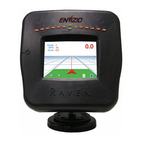
Auto Save Feature Each time the booms are turned off (Envizio Plus stops painting), either by touching the ‘Vehicle Arrow’ or turning off the master boom switch (if the boom sense is set to ‘Wired’), the current job will automatically save. If you do not have the ‘Log’... - Page 58 Envizio Plus LEDs and System Operation The built-in lightbar and LEDs on the front of the Envizio Plus system show guidance as well as system operation. Lightbar LEDs The built-in lightbar shows system guidance similar to that of an external lightbar.
- Page 59 System Operation LEDs Besides use as the built-in lightbar, some of the LEDs illuminate to show system operation functions, as detailed below. • If the lower center green LED is illuminated, DGPS is being received. • If the upper center green LED is illuminated, the system is online. •...
-
Page 60: System Diagrams
System Diagrams EXT LB DGPS... - Page 61 External Lightbar Cables: Description Comments 115-0171-394 Lightbar - wireless Also need 115-0171-629 cable 063-0171-953 Lightbar Also need 115-0171-629 cable 115-0171-401 Lightbar - wireless 063-0171-954 Lightbar 115-0171-628 Lightbar - wireless DGPS Cables: Description 115-0171-361 Invicta 115 115-0171-272 Invicta 210/310 115-0171-119 RPR 410 SmarTrax Controller 115-0171-350 RPR 100G...
-
Page 62: System Hardware
System Hardware Bottom View Power Cable Connection USB Port Right Side View USB Port Left Side View Power Switch... -
Page 63: Troubleshooting
Rear View Fan and Filter Troubleshooting See the table below for possible errors and solutions while using the Envizio Plus: GPS Errors Error Possible Solution(s) Could not find GPS. Make sure Go to the GPS Status screen by the GPS is connected and pow-... -
Page 64: Maintenance
Envizio Plus system. If the Envizio Plus turns on, but does not start-up properly and has a partially blank screen, you will need to ensure that voltage to the Envizio Plus system is at least +9.5 VDC and no greater than +15 VDC. Maintenance... - Page 65 RAVEN INDUSTRIES LIMITED WARRANTY WHAT IS COVERED? This warranty covers all defects in workmanship or materials in your Raven Flow Control Product under normal use, maintenance, and service. HOW LONG IS THE COVERAGE PERIOD? This warranty coverage runs for 12 months from the purchase date of your Raven Flow Control Product.
- Page 66 P.O. Box 5107 www.ravenprecision.com Sioux Falls, SD 57117-5107 fcdinfo@ravenind.com Notice: This document and the information provided are the property of Raven Industries, Inc. and may only be used as authorized by Raven Industries, Inc. All rights reserved under the copyright laws.
Need help?
Do you have a question about the ENVIZIO PLUS and is the answer not in the manual?
Questions and answers