ABB TTF300 Operating Instruction
Field mounted temperature transmitter
Hide thumbs
Also See for TTF300:
- Commissioning instructions (364 pages) ,
- Operating instruction (92 pages) ,
- Manual (48 pages)
Table of Contents
Advertisement
Advertisement
Table of Contents

Related Manuals for ABB TTF300


Summary of Contents for ABB TTF300
- Page 1 Operating Instruction Field mounted Temperature Transmitter OI/TTF300-EN TTF300...
- Page 2 Phone: +49 180 5 222 580 Fax: +49 621 381 931-29031 automation.service@de.abb.com © Copyright 2010 by ABB Automation Products GmbH Subject to changes without notice This document is protected by copyright. It assists the user in safe and efficient operation of the device.
-
Page 3: Table Of Contents
Connection for power supply cable ......................18 Connection for measuring element ......................19 Cable glands ..............................20 5.4.1 TTF300 without cable gland........................20 5.4.2 TTF300 EEx d models without cable gland ..................20 5.4.3 TTF300 EEX d models with standard cable gland................21 Electrical connections...........................23 5.5.1 Standard application ..........................24 5.5.2... - Page 4 2-HART measurement signals ........................44 Sensor redundancy / Sensor backup ......................44 Sensor drift detection ...........................46 Sensor error adjustment (TTF300 DTM: Adjust function / HMI LC display: Calibrate function) ....48 D/A analog output compensation (4 and 20 mA trim) ..................49 HART variable assignment...........................49 Communication / HART tag / Device address....................50...
- Page 5 Intrinsic Safety ATEX / IECEx.......................71 15.4.2 Safety specifications for intrinsic safety ATEX / IECEx ................71 15.4.3 Intrinsically Safe FM..........................72 15.4.4 Non-Incendive FM..........................72 15.4.5 Intrinsically Safe CSA..........................72 15.4.6 Non-Incendive CSA..........................72 Appendix ..............................73 16.1 Additional documents ...........................73 16.2 Approvals and certifications .........................73 Index ................................76 OI/TTF300-EN TTF300...
-
Page 6: Safety
The device is designed for use exclusively within the stated values on the name plate and in the technical specifications (see section "Specifications"). • The maximum operating temperature must not be exceeded. • The permitted operating temperature must not be exceeded. • The housing degree of protection must be observed. TTF300 OI/TTF300-EN... -
Page 7: Target Groups And Qualifications
Prior to using corrosive and abrasive materials for measurement purposes, the operator must check the level of resistance of all parts coming into contact with the materials to be measured. ABB Automation Products GmbH will gladly support you in selecting the materials, but cannot accept any liability in doing so. -
Page 8: Plates And Symbols
Failure to observe this safety information may result in damage to or destruction of the product and/or other system components. IMPORTANT (NOTICE) This symbol indicates operator tips, particularly useful information, or important information about the product or its further uses. It does not indicate a dangerous or damaging situation. TTF300 OI/TTF300-EN... -
Page 9: Name Plate
Name plate The name plate is located on the transmitter housing. Automation TTF300 Made in Germany Products GmbH 2006 O-Code: TTF300-Y0B4/OPT 8323455772 Ser.-No: 3452348673 HW-Rev: 1.05 SW-Rev: 01.00.00 U = +11...42 V, I = 4...20 mA, HART IP6X, NEMA 4X CFG: 2 x TC;... -
Page 10: Safety Information For Electrical Installation
According to EC guidelines for hazardous materials, the owner of hazardous waste is responsible for its disposal or must observe the following regulations for shipping purposes: All devices delivered to ABB Automation Products GmbH must be free from any hazardous materials (acids, alkalis, solvents, etc.). -
Page 11: Disposal
If it is not possible to dispose of old equipment properly, ABB Service can accept and dispose of returns for a fee. 1.10.2 RoHS Directive 2002/95/EC With the Electrical and Electronic Equipment Act (ElektroG) in Germany, the European Directives 2002/96/EC (WEEE) and 2002/95/EC (RoHS) are translated into national law. -
Page 12: Use In Potentially Explosive Atmospheres
Commissioning and operation must comply with EN 60079-14 (Installation of equipment in potentially explosive atmospheres). Approvals The approvals for use of the TTF300 temperature transmitter in potentially explosive atmospheres can be found in the section of the operating instructions titled "Ex relevant specifications". -
Page 13: Design And Function
Design and function Design and function TTF300 digital transmitters are communication-ready field devices with microprocessor- controlled electronics. For bidirectional communication, an FSK signal is superimposed on the 4 … 20 mA output signal via the HART protocol. The graphic user interface (DTM) can be used to configure, poll and test transmitters on a PC- specific basis. -
Page 14: Mounting
Wall installation A00089 Fig. 3 1 Wall 3 TTF300 transmitter 2 Wall mount 1. Locate an installation site close to the temperature sensor head. Warning - General risks! The transmitter can fall and be damaged if not firmly attached. There is also a risk that persons can be injured. -
Page 15: Pipe Installation
Fig. 4 1 Pipe 3 Transmitter 2 Pipe mount TTF300 1. Locate an installation site on a pipe close to the temperature sensor head. Important The pipe mount can be attached to a pipe with a maximum diameter of 2.5 inch. -
Page 16: Installing The Optional Lcd Display With Control Buttons
1 Front view 3 Rear view of LCD display / plug positions 2 Side view The LCD display is attached to the housing of the TTF300 transmitter. Power cables must be disconnected during installation. Warning - General risks! The connection head can be become very hot as a result of the process. There is a danger of burns. -
Page 17: Electrical Connections
From the lower edge of the housing (no cable gland) to the hole in the clamping area, an additional 100 mm of line is needed. An overall line length (without cable gland) of approx. 200 mm is required (approx. 100 mm bared). OI/TTF300-EN TTF300... -
Page 18: Connection For Power Supply Cable
4. Connect the (+) wire to the (+) terminal on the transmitter. 5. Connect the (-) wire to the (-) terminal on the transmitter. The connection of the line shield is optional. TTF300 OI/TTF300-EN... -
Page 19: Connection For Measuring Element
2. Release the clamping screws for terminals 1 to 6 using the proper screwdriver. Make sure that the screws do not fall out. 3. Insert the wires for the measuring element and sensor cable connection under the open terminals and carefully tighten the clamping screws for the connections. OI/TTF300-EN TTF300... -
Page 20: Cable Glands
5.4.2 TTF300 EEx d models without cable gland For delivery of the product variants TTF300-E3... (ATEX EEx d / flameproof enclosure) and TTF300-E4..(ATEX EEx d and EEx ia or flameproof enclosure and intrinsic safety) without cable gland an approved ATEX EEx d cable gland must be used according to EN 50018. -
Page 21: Ttf300 Eex D Models With Standard Cable Gland
Electrical connections 5.4.3 TTF300 EEX d models with standard cable gland General information Type Capri Outer diameter of Material ADE 1F threads cable 816674 No. 4 M20 x 1,5 Ø 6 ... 8.5 mm Nickel-plated brass or stainless steel 818674 No. 4 1/2“ NPT Ø... - Page 22 The customer must provide a strain relief device for the cable. Maintenance Check the glands during each maintenance session. If the cable is slack, retighten the cap(s) of the glands. If it is not possible to retighten them, the gland will need to be replaced. TTF300 OI/TTF300-EN...
-
Page 23: Electrical Connections
1 x RTD, two-wire circuit, and thermocouple protection is enabled 1 x thermocouple DIP switch 2: no function Interface for LC display Ground terminal for sensor and supply- / signal-cable shield connection 1) Sensor backup/redundancy, sensor drift monitoring, mean measurement or differential temperature measurement OI/TTF300-EN TTF300... -
Page 24: Standard Application
≥ 250 Ω (< 1100 Ω). The signal line can be connected with or without ground. When connecting the ground (minus side), make sure that only one side of the contact is connected to the equipotential bonding system. TTF300 OI/TTF300-EN... - Page 25 Mmin Smin Where Minimum operating voltage of transmitter (refer to technical data for transmitter) Mmin Minimum supply voltage of power supply / SPS input Smin : Line resistance between transmitter and power supply : Resistance for HART functionality OI/TTF300-EN TTF300...
- Page 26 ≤ (cable) ≤ Field (Ex area) Control room (secure area) A00096 Fig. 11 A Transmitter B Power supply SPS input Important Observe the “Technical specifications” and “Explosion-protection technical data” chapters (see data sheet and / or operating instructions). TTF300 OI/TTF300-EN...
-
Page 27: Installation In Explosion Risk Area
Fig. 12 A Sensor C Power supply [EEx ia] B Transmitter TTF300 D Interface for LC display The input for the repeater power supply must be designed to "EEx ia". When using the transmitter in Zone 0, you must ensure that impermissible electrostatic charging of the temperature transmitter is prevented (observe the warnings on the device). -
Page 28: Zone 2
Fig. 13 A Sensor C Power supply [EEx ib] B Transmitter TTF300 D Interface for LC display The input for the repeater power supply must be designed to "EEx ib" as a minimum. The user must ensure that sensor instrumentation meets the requirements of applicable Ex standards. - Page 29 Fig. 14 A Sensor C Power supply [EEx ib] B Transmitter TTF300 D Interface for LC display The input for the repeater power supply must be designed to "EEx ib" as a minimum. The user must ensure that sensor instrumentation meets the requirements of applicable Ex standards.
-
Page 30: Dust-Explosion Protection Zone 20
A00130 Fig. 16 A Sensor D Fuse, 32 mA B Transmitter TTF300 E Interface for LC display C Power supply The electric circuit of the transmitter must be limited by an upstream fuse per IEC 127 with a fuse current rating of 32 mA. This is not required if the power supply is in intrinsically safe "ia"... -
Page 31: Dust-Explosion Protection Zone 0/20
Fig. 17 A Sensor C Power supply B Transmitter TTF300 D Interface for LC display When using the sensor in zone 0, the transmitter must be in EEx ia (category 1G) design. If the transmitter is designed with intrinsic safety, the power supply must provide an intrinsically safe circuit. -
Page 32: Flameproof Protection Zone 1
A00132 Fig. 18 A Sensor D Fuse, 32 mA B TTF300 transmitter in Ex d housing E Interface for LC display C Power supply To achieve the flameproof protection, proper mounting of a specially certified cable gland that complies with the standards and relevant Ex designation on the cover sheet of the PTB 99... -
Page 33: Flameproof Protection Zone 0
Fig. 19 A Sensor C Power supply B TTF300 transmitter in Ex d housing D Interface for LC display To achieve the flameproof protection, proper mounting of a specially certified cable gland that complies with the standards and relevant Ex designation on the cover sheet of the PTB 99 ATEX 1144 certificate is required The input for the power supply must be in EEx ia design. -
Page 34: Commissioning
Via HART protocol with FSK modem, PC, and SMART VISION configuration software. • Via DTM in FDT 1.2 frame applications. • Configuration via fieldbus (PROFIBUS), if the superordinate remote I/O system is HART- enabled (e.g., ABB S800 or S900). * If necessary Fig. 20 1 Handheld terminal 3 Ground connection (optional) - Page 35 Configuration can also be performed with EDD master applications such as Siemens Simatic, which is approved for use with EDD. In contrast to DTM configuration, EDD has process- dependent, minor limitations such as configuration of a freestyle characteristic. OI/TTF300-EN TTF300...
-
Page 36: Configuration Via The Lc Display With Control Buttons
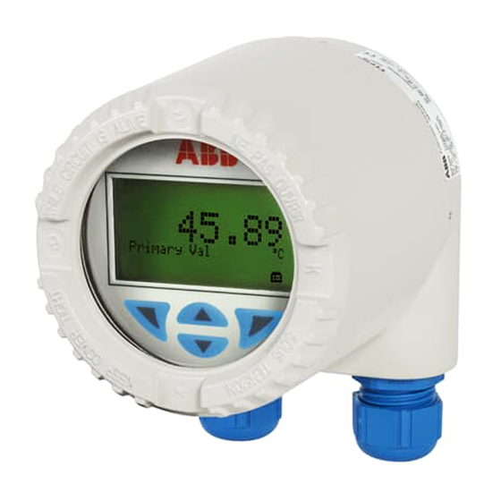
The housing cover must be unscrewed before the transmitter is configured. A00104 Fig. 21 1 Diagnostics 4 HART tag 2 Bar graph 5 Unit 3 Value 6 Optional: bar graph in % of configured measuring range TTF300 OI/TTF300-EN... -
Page 37: Menu Navigation
You can browse through the menu or select a number within a parameter value using the control button. The control button selects the desired menu item. • You can exit a parameter, a submenu, or the main menu at any time using the control button. OI/TTF300-EN TTF300... - Page 38 Fig. 23 1 Entering the menu 1. First, the transmitter voltage supply must be switched on. The “ABB connecting …“ display appears after a few seconds. The “Primary VAL“ value is subsequently displayed. 2. A symbol for calling up the menu is located on the LC display above the control button.
-
Page 39: Example Of Configuration Changes
4. In the submenu “Input Sensor 1” select the sensor type. 5. Use the (2) or (3) control button to select and confirm “TC Type K (IEC 584)”. 6. “Back” via the (1) control button in the submenu “Input Sensor 1” and menu item “Reference Point”. OI/TTF300-EN TTF300... -
Page 40: Activating Write Protection
In the write protection edit mode, an alphanumeric character chain is displayed. 1. Enter master password “0110”. 2. Use the (4) "OK" control button to confirm. The information “Write protection NO” is displayed. Important The master password for deactivating write protection cannot be changed. TTF300 OI/TTF300-EN... - Page 41 Thermocouple RJ* ext. RJ Temperature Input Sensor 2 Sensortype* R-Connection* 2-wire Resistance Thermocouple RJ* ext. RJ Temperature In-output Assignment Sensor 1 Sensor 2 Difference (S1-S2) Difference (S1-S2) Mean value Redundancy Electr. Meas. S1 Electr. Meas. S2 Temp. Electronics OI/TTF300-EN TTF300...
- Page 42 Softwareversion Hardwareversion HART Tag HART Descriptor Operating Time Display Main Operator View Process Variable Sensor 1 Sensor 2 Electr. Meas. S1 Electr. Meas. S2 Temp. Electronics Output Current Output % Bargraph Enable Bargraph View Output current Output % TTF300 OI/TTF300-EN...
- Page 43 HART Burstmode Status* Command # Calibrate Measured range Apply Lower Range Apply Upper Range Analog Output Trim 4 mA Trim 20 mA Diagnostics Looptest Device Status Temp. of Electronics Process value Sensor 1 reset Process value Sensor 2 reset OI/TTF300-EN TTF300...
-
Page 44: 2-Sensor Input Functionality / Dual Sensor Mode
Remote I/O systems such as ABB S900 read out these HART variables on a cyclic basis and provide them to the control system in the form of cyclic process data. - Page 45 22 mA for 50 seconds. The next cycle begins with a 10-second diagnostic alarm signal and subsequently starts again with a 50-second pulse width refresh rate with the normal 4 ... 20 mA temperature signal. OI/TTF300-EN TTF300...
-
Page 46: Sensor Drift Detection
2-HART measurement signal mode, and during averaging. Activation or configuration of sensor drift detection and analog diagnostic signaling (described in the previous section) can only be performed using TTF300 DTM configuration or EDD-based tools. Sensor drift detection can be activated for the following two sensor types (see "electrical connections"):... - Page 47 2 Temperature characteristic for sensor 2 -Off 3 4 ... 20 mA output signal -On -> Configurable pulse width 4 Maximum sensor drift differential -Continuous pulse (e.g., Δ > 1 °C) 6. Sensor drift detection time period (e.g., 2 minutes) OI/TTF300-EN TTF300...
-
Page 48: Sensor Error Adjustment (Ttf300 Dtm: Adjust Function / Hmi Lc Display: Calibrate Function)
2-sensor input functionality / Dual sensor mode Sensor error adjustment (TTF300 DTM: Adjust function / HMI LC display: Calibrate function) Sensor error adjustment can be performed in the TTF300 DTM by navigating to Device / Maintenance / Adjust / Trim low or Trim high. -
Page 49: D/A Analog Output Compensation (4 And 20 Ma Trim)
(Single point error correction: Offset or two-point error correction offset + linear gradient) D/A analog output compensation can be accessed in the HMI LCD display via the menu path Calibrate / Analog Output / Trim 4/20mA or via TTF300 DTM via the path Device / Maintenance / Adjust. -
Page 50: Communication / Hart Tag / Device Address
When burst mode is activated, the device continuously transmits a HART telegram containing reading information approx. every 500 ms without prompting by HART command. In burst mode as with point-to-point mode, the analog output signal is available and matches the primary variable defined during setup. TTF300 OI/TTF300-EN... -
Page 51: Description Of Parameters
Cal. Van Dusen 5 Sensor 1: Sensor <Device> <Device Setup> 2-wire Check safety connection type <Configuration> <Input sensor 1> 3-wire function Type of relevant for all connection <Sensor 1 / <Connection Type> 4-wire Pt, Ni, Cu Connection> resistance sensor types OI/TTF300-EN TTF300... - Page 52 Like sensor 1 connection relevant for all <Sensor 2 / requires check of <Connection Type> Pt, Ni, Cu Connection> following input / resistance output sensor types assignments: Sensor 2 Differential (S1-S2) Differential (S2-S1) Mean Redundancy Elec. reading 2 TTF300 OI/TTF300-EN...
- Page 53 Sensor 2 Parametrized <Device> <Device Setup> Check safety measuring range <Input / output function <Configuration> Sensor 2 of sensor 2 is assignment> <Measurement Type mapped to the / Primary Variable 4 … 20 mA (PV)> analog output OI/TTF300-EN TTF300...
- Page 54 The 4 … 20 mA <Device> <Device Setup> Elec. reading S2 Check safety reading S2 output signal <Configuration> function <Input / output matches the Ω or <Measurement assignment> mV signal of Type / Primary sensor 2 Variable (PV)> TTF300 OI/TTF300-EN...
- Page 55 3.6 mA low alarm <Parametrize> function <Fault Signaling> signal for sensor <Current Output / or device errors Output with Fault> HART tag Defines HART <Device> <Communication> 8 characters, alphanumeric Check safety tag name <Maintenance> <HART Tag> function <Poll Address / Tag> OI/TTF300-EN TTF300...
- Page 56 20.5 mA <Adjust / DAC Sensor URL at compensation fixed 20,000 mA for amplification at setpoint 20 mA> Simulation Output signal <Device> <Diagnostic> 3.5 ... 23.6 mA Check safety simulation <Simulation> function <Loop Test> corresponding to the value specified TTF300 OI/TTF300-EN...
- Page 57 Maintenance Response for maintenance Needs> maintenance needs (e.g., need failure of a sensor in redundancy mode or overshoot of max. sensor drift differential) * Safety check is performed acc. to SIL safety information based on the document SM/TTX3X/SIL-EN OI/TTF300-EN TTF300...
-
Page 58: Factory Settings
Fault signaling Override 22 mA Input Sensor 2 Sensortype In-output Assignment Sensor 1 HART Tag HART Descriptor TIXXX Display Main Operator View Process Variable Bargraph Enable Bargraph View Output % Language English Contrast 50 % Communication HART Burstmode Status TTF300 OI/TTF300-EN... -
Page 59: Error Messages
Diagnostic simulation mode No error, diagnostic info, measurement OK. Sensor Sensor 1 Measuring error. Check sensor connection. Sensor 1 Sensor short-circuit. Check sensor connection. Sensor 1 Wire break. Check sensor connection. Sensor 1 Above sensor range. Check measuring limits. OI/TTF300-EN TTF300... - Page 60 Sensors exceeded Application Calibrate sensors specified drift window Application Reconfiguration is running. Status info, no error. Incorrect application. Application Check configuration, connections; reset to factory settings; notify service. Application Calibration of analog Status info, no error. output active. TTF300 OI/TTF300-EN...
- Page 61 Application Limit LOW LOW. Lower limit value: Alarm Application Limit HIGH. Upper limit value: Warning. Application Limit LOW. Lower limit value: Warning. Explanations per NE 107 Designation Description OK or Information Check Function Off Specification Maintenance Required Failure OI/TTF300-EN TTF300...
-
Page 62: Additional Ttf300 Dtm Diagnostic Information
Additional TTF300 DTM diagnostic information 10 Additional TTF300 DTM diagnostic information Configuration has been changed Important The transmitter indicates that the parameters or configuration data have changed (HART: Configuration changed flag). After intentional or desired reconfiguration, the notification can be acknowledged via the <Reset>... -
Page 63: Maintenance / Repair
Faulty transmitters may not be placed into operation by the user. Repairs must be performed in the production plant. 11.2 Cleaning When cleaning the exterior of meters, make sure that the cleaning agent used does not corrode the housing surface and the gaskets. OI/TTF300-EN TTF300... -
Page 64: Ex Relevant Specifications
Protection type intrinsic safety Ex ia IIC (Part 1) 12.1 TTF300-E1XX, intrinsic safety ATEX Supply circuit Measurement current circuit / passive Explosion protection transducer (RTD) The TTF300 complies with the requirements of Max. voltage = 30 V = 6.5 V ATEX directive 94/9/EC Short circuit = 130 mA = 25 mA Approved for use in Zone 0. -
Page 65: Ttf300-E5Xx, Non-Sparking Atex + Dust Explosion Protection
Class I, Div. 2, Groups A, B, C, D Class II, Groups E, F, G; Class III Explosion protection Control drawing: 214830 The TTF300 complies with the requirements of ATEX directive 94/9/EC Approved for use in Zone 2/22 12.11 TTF300-L3XX, explosion proof FM... -
Page 66: Specifications
(dynamic range: 3.8 ... 20.5 mA in accordance with NE 43) Simulation mode 3.5 ... 23.6 mA Induced current consumption < 3.5 mA Maximum output current 23.6 mA Configurable error current signal Override 22 mA (20.0 … 23.6 mA) Underdrive 3.6 mA (3.5 … 4.0 mA) TTF300 OI/TTF300-EN... -
Page 67: Power Supply (Polarity Safe)
1250 1000 [V DC] [V DC] 11 16 A00001 Fig. 7: TTF300, HART communication resistance TTF300 in EEx ia design Max. power consumption P = U x 0.022 mA → e.g., U = 24 V = 0.528 W OI/TTF300-EN TTF300... -
Page 68: General Information
Change from one to two columns CE Marking 14.2 Electromagnetic compatibility The TTF300 meets all requirements as regards the CE Marking in accordance with Directive 2004 / 108 / EC Emitted interference in accordance with IEC EN 61326 (2006) and... -
Page 69: Measuring Accuracy
1) Percentages refer to the configured measuring span. omitted for PROFIBUS and FOUNDATION Fieldbus 2) Standard model 3) Include the internal reference point error for digital measuring accuracy: Pt1000. IEC 60751 Cl. B 4) Without reference point error OI/TTF300-EN TTF300... -
Page 70: Operating Influences
4) In the case of the option to expand the ambient temperature range up to -50 °C (-58 °F), the causal variables are doubled in the range between -50 ... -40 °C (-58 ... -40 °F) When calculating the influence of the ambient temperature. ME and MS correspond to the measuring ranges of the sensor. as defined by the relevant standard. TTF300 OI/TTF300-EN... -
Page 71: Type B Lcd Hmi
15.1 Features Callendar van Dusen coefficients, warning and alarm limits Software write protection for TTF300 configuration Transmitter-controlled graphic (alphanumeric) LCD display Character height, mode-dependent Sign, 4 digits, 2 decimal places 15.4 Ex relevant specifications... -
Page 72: Intrinsically Safe Fm
= 9V, I i / I < 65.2 mA, P i = 101 mW C i < 0.4 µF, L i = 0 Control Drawing: SAP_214 750 Change from one to two columns Change from one to two columns TTF300 OI/TTF300-EN... -
Page 73: Appendix
Identification for intended use in potentially explosive atmospheres according Protection ATEX directive (marking in addition to CE marking) IEC standards FM Approvals (US) CSA International (Canada) Important All documentation, declarations of conformity, and certificates are available in ABB's download area. www.abb.com/temperature OI/TTF300-EN TTF300... - Page 74 Appendix TTF300 OI/TTF300-EN...
- Page 75 Other toxic substances Radioactive Which substances have come into contact with the device? We hereby state that the devices / components shipped have been cleaned and are free from any dangerous or poisonous substances. Town/city, date Signature and company stamp OI/TTF300-EN TTF300...
-
Page 76: Index
Electrical connections ........23, 44 Note symbols .............8 Electrical interconnection.........26 Error messages..........46, 59 Operating Hours............62 Ex relevant specifications ........71 Operating hours per electronic unit temperature ..62 Ex relevant specifications ........12, 64 Operating influences ..........70 Example of configuration changes......39 Operating safety information........10 TTF300 OI/TTF300-EN... - Page 77 Sensor error adjustment ..........48 Sensor input functionality / Dual sensor mode ..44 Warranty ..............7 Sensor redundancy / Sensor backup ......44 Warranty provisions ...........7 Sensor short circuit ..........66 WEEE Directive ............11 Sensor wire break ............66 Change from one to two columns OI/TTF300-EN TTF300...
- Page 78 ABB has Sales & Customer Support expertise in over The Company’s policy is one of continuous product 100 countries worldwide. improvement and the right is reserved to modify the information contained herein without notice. www.abb.com/temperature Printed in the Fed. Rep. of Germany (04.2010) ©...
Need help?
Do you have a question about the TTF300 and is the answer not in the manual?
Questions and answers