Table of Contents
Advertisement
Available languages
Available languages
www.power-one.com
Aurora
®
Power Service
USA
Aurora
Power Service
France
®
Aurora
Power Service
Germany
®
Aurora
Power Service
Italy
®
Aurora
®
Power Service
Spain
Aurora
®
Power Service
Middle East
Aurora
®
Power Service
Australia
Aurora
®
Power Service
China
Aurora
®
Power Service
Singapore
Aurora
®
Power Service
Malaysia
R
e
. v
3.0
-
A
u
o r
a r
®
is a trademark by Power-One - Product is subject to technical improvements
BCB.00029.5
877-261-1374
00 800 00 28 76 72
0800-2200211
00 800 00 28 76 72
00 800 00 28 76 72
00 800 00 28 76 72
+61 2 9735 3111
+86 755 2988 5888
+65 6896 3363
+603-8025 9963
QUICK INSTALLATION GUIDE
PVI-AEC-EVO
Model:
PVI-AEC-EVO-LIGHT
Advertisement
Chapters
Table of Contents

Subscribe to Our Youtube Channel
Related Manuals for Aurora PVI-AEC-EVO


Summary of Contents for Aurora PVI-AEC-EVO
- Page 1 China +86 755 2988 5888 Aurora ® Power Service Singapore +65 6896 3363 Aurora ® Power Service Malaysia +603-8025 9963 QUICK INSTALLATION GUIDE PVI-AEC-EVO Model: PVI-AEC-EVO-LIGHT ® is a trademark by Power-One - Product is subject to technical improvements BCB.00029.5...
-
Page 2: Monitoring System
PVI-AEC-EVO PVI-AEC-EVO LIGHT Monitoring System - USER MANUAL - QUICK INSTALLATION GUIDE SAVE THESE DOCUMENT IN A SAFE PLACE! IMPORTANT SAFETY INSTRUCTION! This manual contains important safety instruction that must be followed during the installation and start-up of the device. It’s recommended to give special attention to the installation instruction in order to reduce the risks pf electric shock and prevent damage to the device. -
Page 3: Table Of Contents
PVI-AEC-EVO / PVI-AEC-EVO LIGHT QUICK INSTALLATION GUIDE CONTENTS Product Description Package Content User Interface and Use of the Display Pin-Outs of System Connectors Power Supply Connections and System Start Up Date and Time Settings Connection of the RS485 Line and Inverter Acquisition Check... -
Page 4: Product Description
Modbus communication interface. Note: For PVI-AEC-EVO LIGHT, the max number of string inverter manageable by the system is 5, which can be connected only by RS485/2 (Ref.Par.D).Only the followings (in all of their variants) are allowed: PVI-2000(-OUTD) UNO-2.0/2.5-I-OUTD... -
Page 5: Package Content
PVI-AEC-EVO / PVI-AEC-EVO LIGHT QUICK INSTALLATION GUIDE Package content AURORA PVI-AEC-EVO / PVI-AEC-EVO LIGHT Power Supply 100-240Vac 50-60Hz / 24Vdc Power Supply connection cable Quick Installation Guide SD Card (assembled) I/O Terminal Blocks Counterparts (assembled) RS485 Terminal Blocks Counterparts (assembled) -
Page 6: User Interface And Use Of The Display
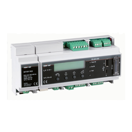
Monitoring System User interface and use of the display The system features a 2x16 character display,four buttons for navigating menus,and three LEDs to indicate device status. Using the display and the buttons on the front panel it is possible to perform the initial configuration of the system (check of parameter acquisition from inverter,analog input configuration,and configuration of LAN network parameters). -
Page 7: D. Pin-Outs Of System Connectors
Use the provided 6) AIn 2 power supply In the PVI-AEC-EVO LIGHT model the RS458/1 port (J17) is not available as inverter communication port, but can be used only to acquire parameters from ISKRAEMECO power meters equipped with Modbus communication interface. -
Page 8: Power Supply Connections And System Start Up
24Vdc.Disconnect the power supply from the power supply network. 2. Connect the output of the power supply to the power supply terminal block of the PVI-AEC-EVO respecting the polarity and using the wiring provided. -
Page 9: Date And Time Settings
The connection of the RS485 line must be carried out respecting the pin-outs of the J15 and/or J17 connectors. Note: For PVI-AEC-EVO LIGHT, the only usable RS485 port for inverter monitoring is the RS485/2, correspondent to connector J15. t is recommended to connect the RS485 line when all the equipment is switched off (both the monitoring system and the inverters) and to start up the monitoring system first and then the inverters. - Page 10 Monitoring System Note: For PVI-AEC-EVO LIGHT, the inverters must be set with addresses: 1, 2, 3, 4, 5. The configuration of address 1 corresponds to "AUTO" settings as inverter address. Note: When connecting multiple units (string inverter or/and 55kW conversion modules) it is necessary to wire the RS485 communication line according to the daisy-chain diagram (enter-exit).
- Page 11 PVI-AEC-EVO / PVI-AEC-EVO LIGHT QUICK INSTALLATION GUIDE 9 - EN...
- Page 12 Monitoring System 10 - EN...
-
Page 13: Configuration Of The Analog Inputs
CHANGE ENTER RACK Note: The time necessary for the PVI-AEC-EVO to scan and acquire the inverters depends on the number of inverterspresentonthesameline(sometimesseveralminutes). Configuration of the Analog Inputs The connection of the analogue sensors must be carried out respecting the pin-outs of the J3 connector. - Page 14 AIn2 input of the system (the selected model will be identified with an asterisk (*) ). Note: In case of connecting PT100/1000 sensors with only two terminals,connect a terminal to the PT_SENSE clampandaterminaltothePT_RTNclamp,thenmakeajumperbetweenPT_ALIMandPT_SENSE. SET PIN TO 0010 PVI-AEC-EVO ..menu pin 12.00.00 01/01/11 0***...
- Page 15 CHANGE INPUT Note: In the following table it is reported a list of the sensor which are present in the catalogue “Power-one” . Fortheconnectionofthesesensors,pleasemakereferencetodiagrams shown in Appendix 1. SENSORS WITH ANALOG OUTPUTS COMPATIBLE WITH PVI-AEC-EVO (POWER-ONE CATALOGUE) MODELL TYPE DISPLAY...
-
Page 16: System Configuration For Connection To The Lan Network (Ethernet Port)
In case of direct connection,it is enough to connect the two devices between them through a Ethernet cable and set the network parameters of PVI-AEC-EVO and of the PC to make sure they are compatible between them. Note: The IP address of the PC and the IP address of the PVI-AEC-EVO must belong to the same group but they... - Page 17 Gateway) compatible with the network parameters set in the PVI-AEC-EVO. DNS parameters fields can be let empty. Note: In case of direct connection between PVI-AEC-EVO and PC we suggest not to set “Gateway” parameters. Note: This type of procedure is to be considered only an example for the most popular operating systems.
- Page 18 Monitoring System CHANGETHE PVI-AEC-EVO NETWORK PARAMETERS :in order to change the PVI-AEC-EVO network parameters,please follow the procedure below: Power on the system and wait for the start up phase to complete (Ref.Par.'E’). Enter the main menu as administrator (Ref.Par.'C’). 3. Access the menu “SETTINGS”...
-
Page 19: Internal Webserver Access
PVI-AEC-EVO / PVI-AEC-EVO LIGHT QUICK INSTALLATION GUIDE Internal Webserver access In order to access to the Webserver pages of the system, after having done the connection of the system to the local network LAN or direct connection to the PC, open an internet browser (e.g. Internet Explorer) and type into the address bar the following address: http://<system IP address>... - Page 20 Monitoring System In order to allow the PVI-AEC-EVO to communicate with the Aurora Vision web portal,access the configuration page (CONFIG) of the network (NETWORK) and check that in section 'DATA TRANSFER', under item 'IP Address Portal' there is the IP address 63.236.63.180...
- Page 21 PVI-AEC-EVO / PVI-AEC-EVO LIGHT QUICK INSTALLATION GUIDE 19 - EN...
-
Page 22: Mac Address Identification
Monitoring System MAC Address Identification During the process of association of PVI-AEC-EVO in Aurora Vision you will be prompted to enter the MAC address of the PVI-AEC-EVO present in the system. It is possible to obtain the MAC Address of your PVI-AEC-EVO observing the label on the right side of the product. -
Page 23: Firmware Updating
9. Remove the SD Card from the SD Card reader or from the SD Card reader slot. 10. Insert the SD Card into the slot on the PVI-AEC-EVO front panel by pressing the SD Card gently to lock it into place. - Page 24 Monitoring System 16. Follow the path “SETTINGS>UPGRADEFIRMWARE>UPGRADEDISPLAY” press ENTER to confirm;wait the completing of upgrade (few minutes).The upgrading process will be completed when the message “Upgrade Success” will be displayed. 17. Follow the path “SETTINGS > UPGRADE CONFIG” press ENTER to confirm; wait the completing of upgrade (few minutes).The upgrading process will be completed when the message “UPGRADE CONFIG”...
- Page 25 PVI-AEC-EVO / PVI-AEC-EVO LIGHT GUIDA DI INSTALLAZIONE RAPIDA INDICE Descrizione del prodotto Contenuto della confezione Interfaccia Utente ed utilizzo del display Piedinatura dei connettori del sistema Collegamento dell’alimentazione del sistema Impostazione di data ed ora Collegamento della linea RS485 e verifica dell’acquisizione degli inverter...
-
Page 26: A. Descrizione Del Prodotto
RS485/1 (rif. capitolo D) per l’acquisizione di parametri da contatori ISKRAMECO MT831 dotati di interfaccia comunicazione Modbus. Nota: Nella versione PVI-AEC-EVO LIGHT il numero di inverter monitorabili è limitato ad un massimo di 5 inverter di stringa,collegabili unicamente alla porta RS485/2 (Rif.Par.D). I modelli compatibili (in tutte... -
Page 27: Contenuto Della Confezione
PVI-AEC-EVO / PVI-AEC-EVO LIGHT GUIDA DI INSTALLAZIONE RAPIDA Contenuto della confezione AURORA PVI-AEC-EVO / PVI-AEC-EVO LIGHT Alimentatore 100-240Vac 50-60Hz / 24Vdc Cablaggio connessione alimentatore Guida di installazione rapida SD Card (assemblata) Controparti morsettiere I/O (assemblate) Controparti morsettiere Rs485 (assemblate) Controparte morsettiera Relè (assemblata) -
Page 28: Interfaccia Utente Ed Utilizzo Del Display
Monitoring System Interfaccia Utente ed utilizzo del display Il sistema dispone di un display 2x16 caratteri, quattro pulsanti per la navigazione nei menu e tre LED che indicano lo stato del dispositivo. Attraverso l’uso del display e dei pulsanti posti sul pannello frontale è possibile effettuare la configurazione iniziale del sistema (verifica dell'acquisizione dei parametri da inverter, configurazione degli ingressi analogici, configurazione dei parametri di rete LAN). -
Page 29: Piedinatura Dei Connettori Del Sistema
Use the provided 6) AIn 2 power supply Nel modello PVI-AEC-EVO LIGHT la porta RS485/1 (J17) non è disponibile per l’acquisizione degli inverter,ma è utilizzabile unicamente per l'acquisizione di parametri da contatori ISKRAEMECO dotati di interfaccia di comunicazione ModBus. 5 - IT... -
Page 30: Collegamento Dell'alimentazione Del Sistema
è in grado di ricevere input da parte dell'utente, il led verde “Power ON” rimarrà stabilmente acceso.A display sarà visibile la scritta“PVI-AEC-EVO..”(nella prima delle due righe) e data/ora (nella seconda delle due righe). -
Page 31: Impostazione Di Data Ed Ora
Il collegamento della linea RS485 deve essere eseguito rispettando la piedinatura dei connettori J15 e/o J17. Nota: Nella versione PVI-AEC-EVO LIGHT l’unica porta RS485 utilizzabile per il monitoraggio degli inverter è la porta RS485/2 contrassegnata dal connettore J15 . - Page 32 Nota: Il numero massimo di unità (inverter di stringa o/e moduli di conversione da 55kW) collegabili ad una porta RS485 del PVI-AEC-EVO è 62; per collegare un numero maggiore di 62 unità è necessario utilizzare la seconda porta RS485/2 rispettando lo stesso schema di collegamento utilizzato per la porta RS485/1 principale.
- Page 33 PVI-AEC-EVO / PVI-AEC-EVO LIGHT GUIDA DI INSTALLAZIONE RAPIDA 9 - IT...
- Page 34 Monitoring System 10 - IT...
-
Page 35: H. Configurazione Degli Ingressi Analogici
CHANGE ENTER RACK Nota: Il tempo impiegato dal PVI-AEC-EVO per effettuare la scansione ed acquisire gli inverter può variare dipendentemente dal numero degli inverter presenti sulla stessa linea (talvolta alcuni minuti). Configurazione degli ingressi analogici Il collegamento dei sensori analogici deve essere effettuato rispettando la piedinatura del connettore J3. - Page 36 Nota: In caso di collegamento di sensori PT100/1000 con due soli terminali, collegare un terminale al morsetto PT_SENSE ed un terminale al morsetto PT_RTN; realizzare poi un ponticello tra PT_ALIM e PT_SENSE. SET PIN TO 0010 PVI-AEC-EVO ..menu pin 12.00.00 01/01/11...
- Page 37 20.0 DEGC CHANGE INPUT Nota: Nella tabella di seguito si riporta la lista dei sensori presenti nel sistema ed offerti a catalogo Power- One. PerlaconnessioneditalisensorifareriferimentoaglischemipresentiinAppendice1. SENSORI CON USCITA ANALOGICA COMPATIBILI CON PVI-AEC-EVO (A CATALOGO POWER-ONE) MODELLO TIPOLOGIA IDENTIFICATIVO RANGE DISPLAY OPERATIVO Sensore Irraggiamento (W/m -->...
- Page 38 La subnet mask deve essere la stessa in entrambi i dispositivi, ad esempio: 255.0.0.0 In caso di connessione ad una rete locale LAN preesistente si rende necessario assegnare al PVI-AEC-EVO dei parametri di rete compatibili con la rete locale al quale il PVI-AEC-EVO è connesso. Fare riferimento all’amministratore di rete per ottenere i corretti parametri di rete.
- Page 39 PVI-AEC-EVO. I campi relativi al DNS possono essere lasciati vuoti. Nota: In caso di connessione diretta tra PVI-AEC-EVO e PC si consiglia di non configurare il parametro “Gateway”. Nota: La procedura indicata è da considerasi di solo esempio per i sistemi operativi più diffusi.
- Page 40 Monitoring System MODIFICA DEI PARAMETRI DI RETE DEL PVI-AEC-EVO Per modificare i parametri di rete del PVI-AEC-EVO seguire la procedura sottostante: 1. Alimentare il sistema ed attendere il completamento della fase di avvio (Rif.Par.”E”). 2. Accedere al menu principale come amministratore (Rif.Par.“C”)
-
Page 41: L. Accesso Al Webserver Interno
PVI-AEC-EVO / PVI-AEC-EVO LIGHT GUIDA DI INSTALLAZIONE RAPIDA Accesso al Webserver interno Per accedere alle pagine di Webserver del sistema dopo aver effettuato la connessione del sistema alla rete locale LAN oppure diretta al PC,aprire un browser internet (es.Internet Explorer) e digitare nella barra degli indirizzi: http://<indirizzo IP del sistema>... - Page 42 Affinchè il PVI-AEC-EVO sia in grado di dialogare con il server di gestione del portale,è indispensabile che la rete LAN nella quale il PVI-AEC-EVO è cablato sia tale da permettere la connessione all'indirizzo IP 63.236.63.180...
- Page 43 PVI-AEC-EVO / PVI-AEC-EVO LIGHT GUIDA DI INSTALLAZIONE RAPIDA 19 - IT...
-
Page 44: M. Identificazione Del Mac Address
Monitoring System Identificazione del MAC Address Durante il processo di associazione dei PVI-AEC-EVO in AuroraVision verrà richiesto di inserire i MAC Address dei PVI-AEC- EVO presenti in impianto. E’possibile ricavare il MAC Address del proprio PVI-AEC-EVO osservando l’etichetta presente sul lato destro del prodotto.Il MAC Address è... -
Page 45: N. Aggiornamento Firmware
3. Spegnere il PVI-AEC-EVO e attendere almeno un minuto. 4. Disconnettere dal PVI-AEC-EVO tutte le connessioni presenti (Linea/e RS485,connessione LAN,sensori). 5. Estrarre la SD Card dallo slot posto sul pannello frontale del PVI-AEC-EVO esercitando una leggera pressione sulla SD Card. - Page 46 Monitoring System 15. Accedere al menu “ SETTINGS” > “UPGRADE FIRMWARE” > “UPGRADE ADC” > Confirm per procedere; attendere il completamento dell'aggiornamento. Il processo di aggiornamento sarà completato quando a display sarà visualizzato il messaggio “UpgradeSuccess”. 16. Accedere al menu“ SETTINGS”...
- Page 47 PVI-AEC-EVO / PVI-AEC-EVO LIGHT SCHNELLINSTALLATIONSANLEITUNG INHALTSVERZEICHNIS Beschreibung des Produkts Packungsinhalt Benutzerschnittstelle und Verwendung des Displays Pinbelegung der Systemstecker Versorgungsanschlüsse und Einschaltung des Systems Einstellung von Datum und Uhrzeit Anschlüsse der Leitung RS485 und Überprüfung der Erfassung der Wechselrichter Konfiguration der Analogeingänge Konfiguration des Systems für den Anschluss an das LAN-Netzwerk (Ethernet-Port)
-
Page 48: Beschreibung Des Produkts
Anschlusskasten sowie für die erweiterten Konfigurationen ist die Öffnung der Seiten des integrierten Internet- Servers erforderlich. Der PVI-AEC-EVO arbeitet in Verbindung mit dem Service-Webportal Aurora Vision: durch die Registrierung für diesen Service ist es moeglich, die Überwachung und Management ueber Remote die Systeme mit Ihrem Account zu verknuepfen. -
Page 49: Packungsinhalt
PVI-AEC-EVO / PVI-AEC-EVO LIGHT SCHNELLINSTALLATIONSANLEITUNG Packungsinhalt AURORA PVI-AEC-EVO / PVI-AEC-EVO LIGHT Stromversorgung 100-240Vac 50-60Hz / 24Vdc Stromversorgungskabel Handbuch Schnellinstallation SD Karte (montiert) Gegenstecker I/O Anschlüsse (montiert) Gegenstecker RS485 Anschlüsse (montiert) Gegenstecker Relaisanschlüsse (montiert) Gegenstecker Stromversorgung (montiert) Output DC 24V 0.75A... -
Page 50: Benutzerschnittstelle Und Verwendung Des Displays
Monitoring System Benutzerschnittstelle und Verwendung des Displays Das System verfügt über ein Display mit 2x16 Zeichen, vier Tasten zum Navigieren in den Menüs und drei LEDs zur Statusanzeige des Geräts. Die Anfangskonfiguration des Systems (Überprüfung der Erfassung der Parameter von Wechselrichtern, Konfiguration der Analogeingänge, Konfiguration der Parameter des LAN-Netzwerks) kann über das Display und die Tasten an der Frontabdeckung vorgenommen werden. -
Page 51: Pinbelegung Der Systemstecker
6) DIn 6 / CONT 1 Use the provided 6) AIn 2 power supply Beim Modell PVI-AEC-EVO-LIGHT kann der Kommunikationsport RS485/1 (J17) nicht fuer die Inverteruebertragung benutzt werden aber nur fuer die Uebertragung / Empfang der Sektoren ISKRAEMECO ausgeruestet mit Kommunikationsinterface Modbus. 5 - DE... -
Page 52: Versorgungsanschlüsse Und Einschaltung Des Systems
Sekunden) während der das System keinen Input vom Benutzer empfangen kann, leuchtet die grüne LED “PowerOn” dauerhaft auf. Auf dem Display werden die Angaben “PVI-AEC-EVO..” (in der ersten der beiden Zeilen) sowie das Datum/Uhrzeit (in der zweiten der beiden Zeilen) angezeigt. -
Page 53: Einstellung Von Datum Und Uhrzeit
PVI-AEC-EVO / PVI-AEC-EVO LIGHT SCHNELLINSTALLATIONSANLEITUNG Einstellung von Datum und Uhrzeit 1. Das Hauptmenü als Administrator (siehe Abschn.“C”) öffnen. 2. Das Menü “SETTINGS” > “DATALOGGER” öffnen und das Untermenü “SET DATE” anwählen. Das korrekte Datum des Systems kann eingestellt werden. 3. In das Menü... - Page 54 Monitoring System Hinweis:Beim PVI-AEC-EVO LIGHT müssen die Adressen 1,2,3,4 und 5 vergeben werden. Die Adresse 1 entsprichtderEinstellung'AUTO'amWechselrichter. Hinweis:Für den Anschluss mehrerer Einheiten (String-Wechselrichter oder/und Wandlungsmodule mit 55kW) muss die RS485-Übertragungsleitung in Übereinstimmung mit dem Daisy-Chain-Schema ("hinein-heraus")verkabeltwerden. Der letzte Wechselrichter der Daisy Chain-Kette wird beendet, indem die Abschlusswiderstand der Ω...
- Page 55 PVI-AEC-EVO / PVI-AEC-EVO LIGHT SCHNELLINSTALLATIONSANLEITUNG 9 - DE...
- Page 56 Monitoring System 10 - DE...
-
Page 57: Konfiguration Der Analogeingänge
ENERGY PLANT CHANGE ENTER RACK Hinweis:Die Zeit die der PVI-AEC-EVO braucht, um die Abtastung auszuführen und die Wechselrichter zu erfassen hängtvonderAnzahlderaufdergleichenLinievorhandenenWechselrichterab(manchmaleinigeMinuten). Konfiguration der Analogeingänge Der Anschluss der Analogsensoren muss unter Beachtung der Pinbelegung des Steckers J3 vorgenommen werden. Das System verfügt über zwei Eingänge desTyps 0-10VDC und einen Eingang desTyps PT100/1000. - Page 58 Sensors anwählen (das angewählte Modell wird mit einem Sternchen (*) gekennzeichnet). Hinweis:Werden PT100/1000 Sensoren mit nur zwei Kontakte angeschlossen,wird ein Kontakt an die Klemme PT_SENSE und ein Kontakt an die Klemme PT_RTN angeschlossen. Danach muss eine Überbrückung zwischenPT_ALIMundPT-SENSEhergestelltwerden. SET PIN TO 0010 PVI-AEC-EVO ..menu pin 12.00.00 01/01/11 0***...
- Page 59 ENTER >T1000-INTEGR 20.0 DEGC CHANGE INPUT Hinweis: In der folgenden Tabelle ist eine Liste von Sensoren ausgefuehrt welche vom Katalog POWER-ONE angebotenwrden.FuerdieVebindungenderSensorengehenSieaufdenAppendix1. SENSOREN MIT ANALOGAUSGANG,DIE MIT DEM PVI-AEC-EVO KOMPATIBEL SIND (KATALOG POWER-ONE) MODELL KENNUNG EINSATZBEREICH DISPLAY SensorSonneneinstrahlung(W/m -->V) PVI-AEC-IRR 0-1200 W/m...
-
Page 60: Konfiguration Des Systems Für Den Anschluss An Das Lan-Netzwerk (Ethernet-Port)
Die subnet mask muss fuer beide Einheiten gleich sein – Beispiel: 255.0.0.0 Bei einer Vebindung mit LAN die vorher Verfuegbar war – muessen die Netzparameter fuer PVI-AEC-EVO neu angelegt werden damit die Einheit mit der Verbindung kompatibel ist. Fragen Sie die korrekten Parameter Ihren System Administrator an. - Page 61 Netzparameter (Adresse IP , Subnet Mask, Gateway) kompatibel mit den Netzparametern konfiguriert in PVI-AEC-EVO. Die Felder fuer DNS koennen leer bleiben. Hinweis: Im Fall einer direkten Verbindung zwischen PVI-AEC-EVO und PC schlagen wir vor den Parameter „Gateway“nichtzukonfigurieren. Hinweis: DieProzedursolltenuralsdasBeispielfürdiegängigstenBetriebssystemeangesehenwerden.
- Page 62 Monitoring System MODIFIKATION DER NETZPARAMETER VON PVI-AEC-EVO: Um die Netzparameter des PVI-AEC-EVO zu modifizieren gehen Sie wie folgt vor: 1. Das System versorgen und abwarten,bis die Startphase abgeschlossen ist (siehe Abschn.“E”). 2. Das Hauptmenü als Administrator (siehe Abschn.“C”) öffnen. 3. Das Menü...
- Page 63 PVI-AEC-EVO / PVI-AEC-EVO LIGHT SCHNELLINSTALLATIONSANLEITUNG Zugang zum Internen Webserver Um auf die Seiten des Webservers zugreifen zu koennen nach einer Verbindung des Systems an einem lokalen LAN Netz oder direkt am PC, wird ein Internet-Browser (bspw.Internet Explorer) geöffnet und in die Adressenleiste wird folgendes http://<IP-Adresse des Systems>...
- Page 64 Monitoring System Damit der PVI-AEC-EVO mit des Webportal Aurora Vision koomminizieren kann die Konfigurationsseite (CONFIG) des Netzes (NETWORK) öffnen und überprüfen,dass in der Sektion "DATATRANSFER" am Menüpunkt "Ip Address Portal" die Adresse IP 63.236.63.180 erscheint. Hinweis:Sollte die eingetragene Adresse des "Ip Portal Address" nicht 63.236.63.180 sein muss sie geändert werden.Die korrekte Adresse eingeben und auf "Confirm"...
- Page 65 PVI-AEC-EVO / PVI-AEC-EVO LIGHT SCHNELLINSTALLATIONSANLEITUNG 19 - DE...
-
Page 66: Identifizierung Der Mac-Adresse
Monitoring System Identifizierung der MAC-Adresse Während der Prozessvernuepfung von PVI-AEC-EVO in Aurora Vision wird man aufgefordert, die MAC-Adresse des PVI- AEC-EVO im System einzugeben. MAC-Adresse kann der Etikette auf der rechten Seite des PVI-AEC-EVO entnommen werden. Die MAC-Adresse besteht aus 12 Zeichen (getrennt durch einen Doppelpunkt) rot in der Abbildung unten welches als Beispiel angezeigt wird. -
Page 67: Firmware Update
SCHNELLINSTALLATIONSANLEITUNG irmware Update Es ist moeglich das Update der Firmware des PVI-AEC-EVO sowie lokal ueber die SD Karte - sowie ueber Remote unter Benutzung desWeb Portals AuroraVision durchzufuehren. Hinweis: Die Firmware-Aktualisierung über SD Card muss nur dann durchgeführt werden,wenn die Firmware- AktualisierungüberWebPortalsAuroraVisionnichtmöglichist. - Page 68 Monitoring System 16. Über “EINSTELLUNGEN” > “UPGRADE FIRMWARE” > “UPGRADE DISPLAY” kann der Upgrade des Display gestartet werden (Enter um zu bestätigen) Dieser Vorgang kann wiederum mehrere Minuten dauern. Ist der Vorgang abgeschlossen wird dies durch die Meldung “Upgradeerfolgreich“ am Display angezeigt. 17.
- Page 69 PVI-AEC-EVO / PVI-AEC-EVO LIGHT GUIDE D'INSTALLATION RAPIDE TABLE DES MATIÈRES Description du produit Contenu de l'emballage Interface Utilisateur et utilisation de l'afficheur Brochage des connecteurs du système Branchements d'alimentation et de mise en marche du système Réglage de la date et de l'heure Branchements de la ligne RS485 et vérification de l'acquisition des onduleurs...
-
Page 70: Description Du Produit
Le PVI-AEC-EVO fonctionne en conjonction avec le service du web portail Aurora Vision: en vous inscrivant à ce service il sera possible de soulveiller et contrôler à distance tous les systèmes associés à votre compte. -
Page 71: Contenu De L'emballage
PVI-AEC-EVO / PVI-AEC-EVO LIGHT GUIDE D'INSTALLATION RAPIDE Contenu de l'emballage AURORA PVI-AEC-EVO / PVI-AEC-EVO LIGHT Alimentation 100-240Vac 50-60Hz / 24Vdc Câble de connexion de l'alimentation Guide d'installation rapide Carte SD (assemblé) Blocs Terminaux homologues E/S (assemblé) Borniers RS485 homologues (assemblé) Borniers Relais homologues (assemblé) -
Page 72: Interface Utilisateur Et Utilisation De L'afficheur
Monitoring System Interface Utilisateur et utilisation de l'afficheur Le système dispose d'un afficheur 2x16 caractères, de quatre boutons pour le défilement à l'intérieur des menus et de trois DELs indiquant l'état du dispositif. En utilisant l'afficheur et les boutons situés sur le panneau avant, il est possible d'effectuer le réglage initial du système (vérification de l'acquisition des paramètres d'onduleurs, réglage des entrées analogiques, configuration des paramètres de réseau LAN). -
Page 73: Brochage Des Connecteurs Du Système
5) AIn 1 6) DIn_RTN 6) DIn 6 / CONT 1 Use the provided 6) AIn 2 power supply Dans le modèle PVI-AEC-EVO LIGHT la porte RS485/1 (J17) n'èst pas disponible poour l'acquisition des onduleurs,mais il est utilisable seulementpourl'acquisitiondesparamètresducompteurISKRAMECOquisontdouésd'uneinterfacedecommunicationModbus. 5 - FR... -
Page 74: Branchements D'alimentation Et De Mise En Marche Du Système
30 secondes) pendant laquelle le système ne peut pas recevoir de commande de la part de l'utilisateur, la DEL verte « PowerOn » reste allumée de façon fixe. Sur l'afficheur, le message « PVI-AEC-EVO..» apparaîtra (sur la première des deux lignes) et date/heure (sur la deuxième ligne à disposition). -
Page 75: Réglage De La Date Et De L'heure
Le branchement de la ligne RS485 doit être effectué en respectant le brochage des connecteurs J15 et/ou J17. Remarque: Pour le PVI-AEC-EVO LIGHT, le seul port RS485 utilisable pour la surveillance de l'onduleur est le port RS485 / 2,correspondant au connecteur J15. - Page 76 Remarque: Le nombre maximum d'unités (onduleurs de chaîne et/ou modules de conversion de 55kW) pouvant être branchés à une porte RS485 du PVI-AEC-EVO est de 62 unités ;pour brancher plus de 62 unités,il est nécessaire d'utiliser la deuxième porte RS485/2 en respectant le même schéma de branchementqueceluiutilisépourlaporteRS485/1principale.
- Page 77 PVI-AEC-EVO / PVI-AEC-EVO LIGHT GUIDE D'INSTALLATION RAPIDE 9 - FR...
- Page 78 Monitoring System 10 - FR...
-
Page 79: Configuration Des Entrées Analogiques
ENERGY PLANT CHANGE ENTER RACK Remarque: Le temps nécessaire au PVI-AEC-EVO pour effectuer une analyse et pour procéder à l'acquisition des onduleurs dépend du nombre d'onduleurs présents sur une même ligne (pouvant aller parfois jusqu'àquelquesminutes). Configuration des entrées analogiques Le branchement des capteurs analogiques doit être effectué en respectant le brochage du connecteur J3. - Page 80 Remarque: En cas de branchement de capteurs PT100/1000 à l'aide de deux terminaux seulement, brancher un terminal sur la borne PT_SENSE et l'autre terminal sur la borne PT_RTN ; puis réaliser un cavalierentrePT_ALIMetPT_SENSE. SET PIN TO 0010 PVI-AEC-EVO ..menu pin 12.00.00 01/01/11...
- Page 81 >CURRENT VALUE DIGITAL VALUE SETTINGS ENTER ENTER >T1000-INTEGR 20.0 DEGC CHANGE INPUT Remarque: Dansletableausuivantilyaunelistedecapteursquisontpresentsdanslesystèmeetilssetrouventaussi danslecataloguePower-One.Pourlaconnexiondecescapteurs,seréférerauxschémassituésàl'Annexe1. CAPTEURS AVEC SORTIE ANALOGIQUE COMPATIBLES AVEC PVI-AEC-EVO (CATALOGUE POWER-ONE) MODELE TYPOLOGIE IDENTIFIANT GAMMEDE AFFICHEUR FONCTIONNEMENT Capteur Rayonnement (W/m --> V) PVI-AEC-IRR 0-1200 W/m PVI-AEC-IRR-T Capteur Rayonnement avec capt.Temp.
-
Page 82: Configuration Du Système Pour Le Branchement En Réseau Lan (Porte Ethernet)
Configuration du système pour le branchement en réseau LAN (porte Ethernet) La connexion du PVI-AEC-EVO à l'ordinateur peut être effectué à travers une connexion directe par le câble Ethernet,ou en joignant les deux dispositives à un réseau local LAN (par router,hub ou switch). - Page 83 PVI-AEC-EVO. Les champs relatives au DNS peuvent être laissés vides. Remarque: En cas de connexion directe entre PVI-AEC-EVO et ordinateur il est conseillé de ne pas configurer le paramètre "Gateway". Remarque: Le type de procédure doit être considérée seulement un exemple pour les systèmes d'exploitation les plus populaires.
- Page 84 MODIFIER LES PARAM TRES DU R RESEAU DU PVI-AEC-EVO È É Pour modifier les paramètres du réseau du PVI-AEC-EVO il faut suivre la procédure suivante: 1. Mettre sous tension le système et attendre que la phase de démarrage ait terminé (cf.Paragraphe « E ») Accéder au menu principale en tant qu'administrateur (cf.Paragraphe «...
-
Page 85: Accès Au Webserver Interne
PVI-AEC-EVO / PVI-AEC-EVO LIGHT GUIDE D'INSTALLATION RAPIDE Accès au Webserver Interne Pour acceder aux pages du Webserver du système après avoir effectué la connexion du système au réseau local LAN ou direct à l'ordinateur ouvrir un browser internet (par ex.Internet Explorer) et taper dans la barre d'adresse : http://<adresse IP du système>... - Page 86 Monitoring System Pour permettre au PVI-AEC-EVO de communiquer avec le portail web AuroraVision,accéder à la page de réglage (CONFIG) du réseau (NETWORK) et vérifier que dans la section « DATA TRANSFER » et dans la rubrique « Ip Address Portal »...
- Page 87 PVI-AEC-EVO / PVI-AEC-EVO LIGHT GUIDE D'INSTALLATION RAPIDE 19 - FR...
-
Page 88: Identification De L'adresse Mac
Monitoring System Identification de l'adresse MAC Pendant le processus d'association des PVI-AEC-EVO à Aurora Vision vous serez invité à entrer l'adresse MAC du PVI-AEC- EVO présent dans le système. Il est possible d'obtenir l'adresse MAC de votre PVI-AEC-EVO en observant l'étiquette sur le côté droit du produit. -
Page 89: Mise À Jour Du Firmware
PVI-AEC-EVO / PVI-AEC-EVO LIGHT GUIDE D'INSTALLATION RAPIDE Mise à jour du Firmware Il est possible de mettre à jour le firmware du PVI-AEC-EVO, soit localement à l'aide de la carte SD, ou à distance via le portail web AuroraVision. Remarque: Lamiseàjourdumicrologicielàl'aided'unecarteSDdoitêtreeffectuée uniquementdanslecasoù... - Page 90 Monitoring System 16. Suivre le chemin suivant: « UPGRADE FIRMWARE » « UPGRADE DISPLAY » > presser ENTER pour confirmer;attendre la fin de la mise à jour (quelques minutes).La mise à jour sera finie lorsque le message «UpgradeSuccess » s'affichera. 17.
- Page 91 PVI-AEC-EVO / PVI-AEC-EVO LIGHT QUICK INSTALLATION GUIDE Appendix 1. Wiring Diagrams for compatible sensors Wiring Diagrams for the Sensors PVI-AEC-T100-ADH 1 - APPENDIX...
- Page 92 Monitoring System Wiring Diagrams for the Sensors PVI-AEC-T1000-BOX 2 - APPENDIX...
- Page 93 PVI-AEC-EVO / PVI-AEC-EVO LIGHT QUICK INSTALLATION GUIDE Wiring Diagrams for the Sensor PVI-AEC-T1000-INTEGR 3 - APPENDIX...
- Page 94 Monitoring System Wiring Diagrams for the Sensors PVI-AEC-IRR / PVI-AEC-RAD-13TC 4 - APPENDIX...
- Page 95 PVI-AEC-EVO / PVI-AEC-EVO LIGHT QUICK INSTALLATION GUIDE Wiring Diagrams for the Sensors PVI-AEC-IRR-T / PVI-AEC-RAD-13-TC-T 5 - APPENDIX...
- Page 96 Monitoring System Wiring Diagrams for the Sensors PVI-AEC-PYR-1300 6 - APPENDIX...
- Page 97 PVI-AEC-EVO / PVI-AEC-EVO LIGHT QUICK INSTALLATION GUIDE Note: The internal heater (+Vcc_Heat and -Vcc_Heat) must be supplied by supplementary power supply. For more details about internal heater refer to PVI-AEC-EVO User Manual. Wiring Diagrams for the Sensor PVI-AEC-WIND-COMPACT 7 - APPENDIX...
- Page 98 Monitoring System Note: The internal heater (+Vcc_Heat and -Vcc_Heat) must be supplied by supplementary power supply. For more details about internal heater refer to PVI-AEC-EVO User Manual. Wiring Diagrams for the Sensor PVI-AEC-WIND-DIR 8 - APPENDIX...
- Page 99 PVI-AEC-EVO / PVI-AEC-EVO LIGHT QUICK INSTALLATION GUIDE 2. RS485 Cable Specification SINGLE TWISTED PAIR RS485 CABLE SPECIFICATION Type of Cable RS485 EIA Application Cable Structure 1 twisted pair + 1 single conductor, shielded 22 - 24 Ω Charateristic Impedance Working Frequency...
- Page 100 Monitoring System 3. Display flow-charts MAIN PAGE INFORMATION SETTINGS PRODUCT DATALOGGER NETWORK SET DATE FIRMWARE AVR SET TIME FIRMWARE BOOTLOADER IO SETTINGS FIRMWARE ADC_IO ANALOG INPUT 1 FIRMWARE DISPLAY ANALOG INPUT 2 NETWORK DIN 1-4 CURRENT IP ADDRESS DIN 6/IN_CONT 1 CURRENT SUBNET DIN 5/IN_CONT 2 CURRENT GATEWAY...
- Page 101 PVI-AEC-EVO / PVI-AEC-EVO LIGHT QUICK INSTALLATION GUIDE 4. Compliance Requirements 11 - APPENDIX...
- Page 102 Monitoring System 12 - APPENDIX...
- Page 103 PVI-AEC-EVO / PVI-AEC-EVO LIGHT QUICK INSTALLATION GUIDE 13 - APPENDIX...
- Page 104 Monitoring System 14 - APPENDIX...
- Page 105 PVI-AEC-EVO / PVI-AEC-EVO LIGHT QUICK INSTALLATION GUIDE 15 - APPENDIX...
- Page 106 Monitoring System NOTE: The Models PVI-AEC-EVO and PVI-AEC-EVO LIGHT has been tested and found to comply with the limits for a Class B digital device, pursuant to Part 15 of the FCC Rules.These limits are designed to provide reasonable protection against harmful interference in a residential installation.
Need help?
Do you have a question about the PVI-AEC-EVO and is the answer not in the manual?
Questions and answers