Table of Contents

Related Manuals for ROC COMBI HE 2802


Summary of Contents for ROC COMBI HE 2802
- Page 1 Manual for Installation and Maintenance Condensing Wall Mounted Gas Fired Combination Boilers: ROC COMBI HE 2802 ROC COMBI HE 2810 ROC COMBI HE 4010 G.C.N:47-492-01(28 KW) G.C.N:47-492-02(40 KW) Suitable for: Installation Personnel ● Service Provider ●...
-
Page 3: Table Of Contents
CONTENT Overview Appliance adjustment Reading advices........4 Check the circuit and power.....29 Customer care........4 Cleaning of heating system....29 Advice for the installer.......5-6 Checks before operation.....30-31 CE symbol..........6 First operation......31-33 Safe regulations........7-8 ECS Control Operations....33 ECS parameter chart......34 Product description Flue gas analysis......35 Control panel........9 Capacity adjustment....35-36 Display..........9... -
Page 4: Overview
Email: info@rocboilers.co.uk GUARANTEE ROC Combi Boilers 2810 and 4010 both come with a Parts and Labour Warranty for 10 years from the date of Installation, ROC Combi boiler 2802 has a 2 Year parts and Labour Warranty from the date of installation. For full details and registration visit www.rocboilers.co.uk. -
Page 5: Advice For The Installer
Advice for the installer The boiler is delivered in a carton. Once you have removed all packaging, make sure the appliance is intact and that no parts The installation and first ignition of the are missing. If this is not the case, please boiler must be performed by qualified contact your supplier. -
Page 6: Ce Symbol
Clean using a cloth dampened with soapy Symbols used on the data plate water. Do not use aggressive detergents, insecticides or toxic products. If the appliance is used in full compliance with current legislation, it will operate in a safe, environmentally-friendly and cost-efficient manner. -
Page 7: Safe Regulations
Safety regulations Use suitable manual tools and equipment Key to symbols: (make sure in particular that the tool is not worn out and that its handle is fixed Failure to comply with this warning properly); use them correctly and make implies the risk of personal injury, in some sure they do not fall from a height. - Page 8 Personal injury caused by falling from a Damage to the appliance or surrounding height. objects from shocks, knocks, incisions and During all work carried out at a certain squashing. height (generally with a difference in All operations inside the appliance must height of more than two metres), make be performed with the necessary caution sure that parapets are used to surround the...
-
Page 9: Product Description
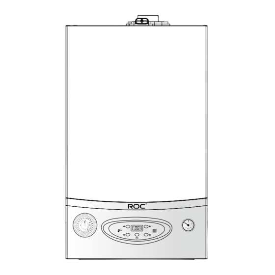
PRODUCT DESCRIPTION Control panel 1).Timer 4).ON/OFF (Power) button (Central heating/ Hot 2).D.H.W. temperature up/down button Water only mode) 3).Display 5).Heating temperature up/down button 6).Pressure gauge Display 1. Flame indication icon (flame 4. Central heating icon (indicator indicates when burning) flashes when performing heating 2. -
Page 10: Overall View
Overall view 1.Main heat exchanger 14.Overheat protector 15.Ignition needle 2.Flue gas temperature sensor 3.Syphon 16.Burner 4.Heating temperature sensor 17.Flame detection needle 5.Electric box 18.Three way motor 6.Timer 19.Domestic heat exchanger 7.Fan 20.Gas valve 8.Gas/air mixed burner 21.Pressure switch 9.Air inlet pipe (burner) 22.Hot water temperature sensor 10.Expansion tank 23.Water flow volume sensor... -
Page 11: Overall Dimension
Overall dimension ROC COMBI HE 28 A. Gas B. Domestic hot water C. Cold water D. Inlet of central heating water E. Outlet of central heating water F. Pressure relief valve pipe ROC COMBI HE 40 A. Gas B. Domestic hot water C. - Page 12 Minimum clearance In order to allow easy access to the boiler for maintenance, operation, the boiler must be in accordance with the clearances stated below. The following minimum distance should be left for equipment’s installation and maintenance. - Distance on the bottom:300mm - Distance on the side position:5mm - Distance on the top:300mm - Distance on the front :500mm...
-
Page 13: Technical Data
Technical data ROC COMBI HE 28 ROC COMBI HE 40 Model Boiler type 51CN4162(LJLGB26-B28CP) 51CN4162(L1GB37-B40CP) CE Certification Capacity 26.0/5.2 36.0/6.0 Max/min nominal calorific flow rate(Pci) 28.8/5.8 39.9/6.7 Max/min nominal calorific flow rate(Pcs) 25.7/5.1 35.5/5.9 Max/min power output(80°C-60°C) 27.4/5.5 37.8/6.3 Max/min power output(50°C-30°C) -
Page 14: Appliance Installation
APPlIANCE INSTAllATION Reference standard BS EN 12828:2003 Heating systems in buildings. Design for In the United Kingdom, the installation and water-based heating systems. initial start-up of the boiler must be by a Gas Safe registered installer in accordance with the BS EN 12831:2003 Heating systems in installation standards currently in effect, as... -
Page 15: Ventilation
Water supply Condensing boilers have a tendency to form a plume of water vapour from the flue terminal due to the low temperature of the flue gasses. The boiler is suitable for sealed systems The terminal should therefore be located with only. -
Page 16: Shower
Under no circumstances should the boiler be fired before the system has been thoroughly ROC suggests that use of suitable anti-freeze flushed; the flushing procedure must be in line products such as Fernox, which will prevent with BS 7593:2006. -
Page 17: System Controls
The condensate discharge voltage free contacts should be used. pipe must have a minimum diameter 22mm, ROC supply a range wire and wireless system must have a continuous fall and preferably be controls, please contact your supplier for more installed and terminated to prevent freezing. -
Page 18: Condensate Discharge
iii) Terminating into a gully, below the grid 2. External termination of condensate drainage level but above the water level pipe via internal discharge branch (e.g. sink waste) and condensate siphon. iv) Into a soakaway Note: If any condensate pipework is to be installed externally then it should be kept to a minimum and be insulated with a waterproof insulation and have a continuous fall. -
Page 19: Installing The Boiler
Installing the boiler 4. External termination of condensate drainage pipe via condensate siphon Please check that you are familiar with the installation requirement before commencing work. The installation accessories described in the following list are included in the boiler package: Boiler Box: - Gas boiler - Connection valves... -
Page 20: Opening The Box
Opening the box The appliance was packed in a hard box with foam protection. Pay attention that the arrow in the carton should be down when opening the box. (Refer to below diagram) Position the boiler on the wall Installation of pipework Fix the paper template to the wall to ensure the Remove the caps and valves from the boiler. -
Page 21: Draining The Boiler
Water connection Draining the boiler To drain the water contained within the boiler, Please ensure the pipe system has been flushed completely before connecting the attach a pipe (garden hose pipe) to the outlet on the pump – (diagram required). Use a 10/8 cold supply to the boiler. - Page 22 Connecting the flue Note: The appliance must be installed so that the flue -A Directly below an opening, window, etc 300mm terminal is exposed to outdoor air. -B Horizontally to a window 300mm The terminal must not discharge into another -C Below gutters, soils pipes or drain pipes 75mm room or space such as an outhouse or lean-to.
-
Page 23: Flue System
Flue system Standard 100mm flue system includes: 1) Horizontal flue duct with external wall seal 2) 90° elbow 3) 2X30mm flue duct clamp 4) Internal trim ring 5) External wall seal Standard flue installation... -
Page 24: Flue System
Important Warning! The flue must not be in contact with or close to Ensure that the flue is not blocked. inflammable material and must not pass through Ensure that the flue is supported and building structures or walls made of inflammable assembled in accordance with these material. - Page 25 If the flue requires extending, the connections are push fit, but ensure each meter is secured with a flue bracket. Before installing the flue, ensure the maximum length of flue ducting does not exceed 10m for the 28Kw and 5m for the 40Kw. You should reduce the maximum length of the flue by 1m for each 90°...
-
Page 26: Instruction And Precautions For Power Connection
Instruction and precautions for power connection ● The boiler should not have a plug socket only a flex ● Voltage/frequency for the gas boiler:230 V~/50Hz ● Please obey the following steps when operate the gas boiler: -- Do not touch the appliance with parts of the body that are wet or damp and/or bare feet. -
Page 27: Connecting Additional Controls
Connecting additional controls... -
Page 28: Appliance Commissioning
Appliance commissioning The boiler heats the heating water/ hot water/ domestic hot water (DHW) to a certain temperature. Before supplying heating/ Warning! This boiler can only be used for domestic hot domestic hot water to the users, the boiler water and indoor heating! should be connected to a heating supplying network, heat dissipation device and/ or The gas boiler was designed for inside room... -
Page 29: Appliance Adjustment
APPlIANCE ADjUSTMENT Check the circuit and power ● Open the central heating flow and return cock supplied with the connection kit. ● Check i f t h e v o lt ag e m a t ch e s w i th th e Lift the cap on the automatic air release requirements, if the polarity of power is valve and leave open permanently. -
Page 30: Checks Before Operation
If the gas supply serves other appliances, Please check the following steps before turn ensure that an adequate supply is available on the gas boiler: ● both to the boiler and the other appliances Technical data on the data plate must when they are in use at the same time. -
Page 31: First Operation
Add water to appliance Please close gas main valve when the user is not at home for long periods, you should also If you notice that the pressure on the pressure drain out the water from heating and hot water gauge is below 1.0~1.2 bar, you will have to system to avoid water freezing in the system. - Page 32 1).Timer 4).ON/OFF (Power) button (Central heating/ Hot 2).D.H.W. temperature up/down button Water only mode) 3).Display 5).Heating temperature up/down button 6).Pressure gauge Heating Note: The display will show when The boiler has a built-in anti-short time circle the boiler has power. Press ON/OFF button energy saving control program.
-
Page 33: Ecs Control Operations
Setting the hot water temperature temperature down” button to select a Press hot water temperature up parameter, then press ON/OFF and “Heating down button to set the temperature temperature up” at the same time to of hot water (press “up” button to increase show the real valve of the selected parameter. -
Page 34: Ecs Parameter Chart
ECS Parameter Chart Program Description Default Value Value number Pr07 Highest heating 50/60/80/85°C temperature setting Pr09 Scanning test function 01=Minimum power scanning test activation 04=heating power scanning test Pr10 Anti-circulating time 06 (1 minute) 03=30 Seconds 06=60 Seconds 18=180 Seconds Pr12 Max. -
Page 35: Flue Gas Analysis
When conducting flue gas analysis or power adjustment, the CO of the flue gas and revolving speed of the fan should correspond with the following table: ROC COMBI HE 28 Power Air speed (rpm) Max. power 6200-6600 9.2±0.2 Min. - Page 36 3.) Maximum power adjustment: re-enter ECS menu “PR09 parameter 04” (you may have to reenter this menu several times as the program only lasts for 20 seconds) Now adjust the screw with 2.5mm spanner (picture-R) and make the value of CO achieve the required point (CO %=9.2±0.2).
-
Page 37: Maintenance
MAINTENANCE Precautions Anti-freeze function ● The gas boiler has anti-freeze function. Installation and maintenance of the gas boiler must be performed by the installer/ If the gas and power is on, the boiler will start e n g i n e e r a c c o r d i n g t o t h e o p e r a t i o n to work automatically when the heating water instructions of the manufacturer and local temperature is below 5... -
Page 38: Error Codes
Error Codes Description Code Flame cannot be detected after ignition (Ignition fault) Er 01 + RESET Overheat inside Er 02 + RESET Residual flame fault (Flame signal can be detected after Er 03 + RESET the gas valve is closed) Water pressure fault in pipeline Er 04 + Fan control fault/Air pressure switch... - Page 39 Er 01 Fault: Er 06 Fault: When the display shows Er01 fault, it means Er 06 indicated that the temperature of the flame cannot be detected. Check if the heating water is unusual, it could be caused gas elements and pressure; if there is any air by extremely cold water, or damage of the inside the gas pipe;...
- Page 40 Er 13 Fault: Er 18 Fault: Test the actual working frequency of the Er13 means EEPROM fault has occurred on the inner circuit board. Please replace the power within the beginning 5 seconds before circuit board. connecting to the power to confirm the reference working frequency.
-
Page 41: Gas Boiler Dismantling Instruction
GAS BOIlER DISMANTlING INSTRUCTION General access General access Time: 3 min Tools: Use screw driver unscrew Lift the plastic panel from Turn around the plastic the two screws of bottom bottom. panel plate. General access Tools: Unscrew the 4 screws Dismantle the facing Unlock the upper buckle. -
Page 42: General Access
General access Tools: Unscrew the 4 screws Dismantle the facing of the sealing cover of cover from front. combustion system... -
Page 43: Circuit Component
Circuit component Electrical box operation Time: 4 min Tools: Take out the screws Take out the Electrical on the both sides of box back cover upward. Electrical box Fuse replacement Time: 4 min Tools: Open the Electrical box as Remove the fuse shown above... -
Page 44: Pcb And Display
PCB and Display PCB replacement Time: 6 min Tools: Operate Electrical box as Remove the PCB Dismantle the 4 screws shown above on the PCB Display Replacement Time: 7 min Tools: Operate PCB as shown Dismantle the 4 screws Remove the display above on the PCB... -
Page 45: Water System
Water system Three way valve dismounting Time: 5 min Tools: First take out the motor Unscrew the motor clip radial, and then take connector by spanner, out the motor axially. take out the inside three way component axially. Bypass valve dismantling Time: 5 min Tools: Unscrew the bypass valve... -
Page 46: Safety Valve And Exhaust Valve
Safety valve and Exhaust valve Safety valve dismantling Time: 5 min Tools: Take out the safety valve Take out the safety valve manually. clip Exhaust valve dismantling Time: 5 min Tools: Take out the exhaust Take out the exhaust valve manually. valve clip... -
Page 47: Pump And Plate Heat Exchanger
Pump and Plate heat exchanger Pump dismounting Time: 12 min Tools: Dismantle the front Separate the bottom plate Take out the pump from two screws which for and water system. right side. connecting water system. Plate heat exchanger dismantling Time: 3 min Tools: Dismantle the 2 screws Pull the domestic heat... -
Page 48: Combustion System
Combustion system Combustion system dismounting Time: 5 min Tools: Dismantle the 2 installation screws flame testing needle or ignition Dismantle the 4 screws needle as shown above, Dismantle the combustion of maintain cover on top, then take out the flame chamber sealing cover and take out the maintain testing needle or ignition... -
Page 49: Fan
Fan dismantling Time: 8 min Tools: Dismantle the 4 nuts connected with fan by 8mm spanner, and then Dismantle the combustion Take out the whole fan dismantle the connected chamber sealing cover and silencer. gas pipe by 24mm following the basic spanner. -
Page 50: Main Heat Exchanger
Main heat exchanger Heat exchanger dismounting Time: 23 min Tools: Dismantle the 4 nuts connected with fan by Dismantle the combustion 8mm spanner, and then Take out the whole fan chamber sealing cover dismantle the connected and silencer. following the basic gas pipe by 24mm dismantling method. - Page 51 Heat exchanger dismounting Tools: Unscrew the 2 heating outlet water pipe Dismantled the 4 screws Take out the inside connection nuts by on the smoke pipe outlet smoke pipe connection 30mm spanner; take by screwdriver and take pipe upwardly. heating outlet water pipe out the outlet flange.
- Page 52 Heat exchanger dismounting Tools: Dismantle the screws connected with heat Take out the whole heat Dismantled the 2 screws exchange and smoke exchange and smoke on heat exchanger. collector and separate collector. them.
-
Page 53: Annual Maintenance
Annual Maintenance Plate type heat exchanger. Maintenance interval: Yearly. Method: Visual inspection for leaks Safety valve Maintenance interval: Yearly. Method: Visual inspection/Clean if necessary. Water flow sensor Maintenance interval: Yearly. Method: Visual inspection/Clean if necessary/ Check the flow. Expansion tank Maintenance interval: Yearly. - Page 54 Condensate water collector Maintenance interval: Yearly (or after cleaning the main heat exchanger). Method: Visual inspection/clean if necessary (add water before clean). Pump Maintenance interval: Yearly after the first ignition. Method: Check the AAV if it’s open/visual inspection/ clean if necessary. Burner combustion chamber Maintenance interval: Yearly (or after cleaning the main heat exchanger).
- Page 60 ROC UK UK HD Ltd 14 Lenton Business Centre Lenton Boulevard Nottingham NG7 2BY Support Number 08452268261 Email info@rocboilers.co.uk...
Need help?
Do you have a question about the COMBI HE 2802 and is the answer not in the manual?
Questions and answers