
Related Manuals for MDV MS1Ai-09HRFN1


Summary of Contents for MDV MS1Ai-09HRFN1
-
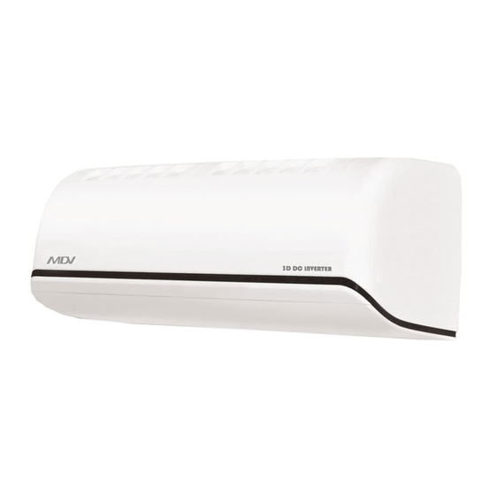
Page 1: Service Manual
1ASFI-1103-A SERVICE MANUAL MDV AIRCONDITIONER EUROPE MARKET SPLIT WALL-MOUNTED TYPE 1A INVERTER SERIES... -
Page 2: Table Of Contents
CONTENTS 1. Precaution ..............................1 1.1 Safety Precaution .......................... 1 1.2 Warning ............................1 2. Function ................................ 6 3. Dimension ..............................9 3.1 Indoor Unit ............................. 9 3.2 Outdoor Unit ..........................10 4. Refrigerant Cycle Diagram ........................11 5. Wiring Diagram ............................12 5.1 Indoor Unit ........................... -
Page 3: Precaution
1. Precaution 1.1 Safety Precaution To prevent injury to the user or other people and property damage, the following instructions must be followed. Incorrect operation due to ignoring instruction will cause harm or damage. Before service unit, be sure to read this service manual at first. 1.2 Warning ... - Page 4 For installation, always contact the dealer or an Authorized service center. There is risk of fire, electric shock, explosion, or injury. Do not install the product on a defective installation stand. It may cause injury, accident, or damage to the product. ...
- Page 5 If strange sounds, or small or smoke comes from product. Turn the breaker off or disconnect the power supply cable. There is risk of electric shock or fire. Stop operation and close the window in storm or hurricane. If possible, remove the product from the window before the hurricane arrives.
- Page 6 the neighborhoods. It may cause a problem for your neighbors. Use two or more people to lift and transport the product. Avoid personal injury. Do not install the product where it will be exposed to sea wind (salt spray) directly. It may cause corrosion on the product.
- Page 7 It is not sanitary could cause serious health issues. Use a firm stool or ladder when cleaning or maintaining the product. Be careful and avoid personal injury. Replace the all batteries in the remote control with new ones of the same type. Do not mix old and mew batteries or different types of batteries.
-
Page 8: Function
2. Function Model Names of Indoor/Outdoor Units Capacity Indoor units Outdoor units MS1Ai -09HRFN1 MOC3i -09HFN1 MS1Ai -12HRFN1 MOC3i -12HFN1 Inverter... -
Page 9: Indoor Unit
Indoor unit Self clean function Operation by remote controller Concealed display Anti-freezing control in cooling mode Prevent the water being frozen on evaporator by checking the evaporator coil temperatur Silence operation Time Delay Safety control Golden fin (Optional) Indoor fan speed control Turbo wind, high, med, low, auto Ionizer (Optional) Two-direction air vane... -
Page 10: Outdoor Unit
Outdoor unit Power relay control Low noise air flow system Hydrophilic aluminum fin The hydrophilic fin can improve the heating efficiency at operation mode. 4 way valve control It is only operated in the heating operation mode except defrosting operation. Anti-rust cabinet Made from electrolytic zinc steel sheet and anti-rust coated components. - Page 11 3. Dimension 3.1 Indoor Unit For MS1Ai -09HRFN1, MS1Ai-12HRFN1 units, Dimension (mm) Model MS1Ai-09HRFN1 MS1Ai-12HRFN1...
- Page 12 3.2 Outdoor Unit Model MOC3i -09HFN1 MOC3i -12HFN1...
-
Page 13: Refrigerant Cycle Diagram
4. Refrigerant Cycle Diagram... -
Page 14: Wiring Diagram
5. Wiring Diagram 5.1 Indoor Unit MS1Ai-09HRFN1 MS1Ai-12HRFN1... -
Page 15: Outdoor Unit
5.2 Outdoor Unit MOC3i -09HFN1 MOC3i -12HFN1... -
Page 16: Installation Details
6. Installation details 6.1 Wrench torque sheet for installation Additional Outside diameter Torque tightening torque inch N.cm N.cm 1500 1600 Ф6.35 (153kgf.cm) (163kgf.cm) 2500 2600 Ф9.52 (255kgf.cm) (265kgf.cm) 6.2 Connecting the cables The power cord of connect should be selected according to the following specifications sheet. Nominal cross-sectional area (mm²) Rated current of appliance >3 and ≤6... -
Page 17: Pipe Length And The Elevation
The pipe length and refrigerant amount: Connective pipe Additional amount of Model Air purging length refrigerant Use vacuum Less than 5m ------------------ pump MS1Ai-09HRFN1 MS1Ai-12HRFN1 Use vacuum (Pipe length – 5) × 20g/m More than 5m pump Standard Max. Max. Model length... -
Page 18: Air Purging With Vacuum Pump
6.4 Air purging with vacuum pump Air and moisture in the refrigerant system have undesirable effects as below: ● Pressure in the system rises. ● Operating current rises. ● Cooling or heating efficiency drops. ● Moisture in the refrigerant circuit may freeze and block capillary tubing. ●... -
Page 19: Pumping Down (Re-Installation)
out, then tighten the flare nut again. Make sure the pressure display in the pressure indicator is a little higher than the atmosphere pressure. 7. Remove the charge hose from the Lo pressure charge hose. 8. Fully open the Hi and Lo packed valve. 9. -
Page 20: Re-Air Purging (Re-Installation)
Open the low-pressure valve on the charge set slightly to purge air from the charge hose. 5. Set the 2-way valve to the close position. 6. Operate the air conditioner at the cooling cycle and stop it when the gauge indicates 0.1MPa. 7. -
Page 21: Evacuation
After purging the air, use a torque wrench to tighten the flare nut to on the 2-way valve. 4. Check the gas leakage. Check the flare connections for gas leakage. 5. Discharge the refrigerant. Close the valve on the charging cylinder and discharge the refrigerant until the gauge indicates 0.3 to 0.5 Mpa. -
Page 22: Gas Charging
6.9 Gas charging Procedure: 1. Connect the charge hose to the charging cylinder. Connect the charge hose which you disconnected from the vacuum pump to the valve at the bottom of the cylinder. If the refrigerant is R410A, make the cylinder bottom up to ensure liquid charge. 2. -
Page 23: Operation Characteristics
7. Operation characteristics Temperature Cooling operation Heating operation Drying operation Mode >10℃ ≥17℃ ≤30℃ Room temperature -15℃ ~50℃ Outdoor temperature -20℃~34℃ 0℃~50℃ CAUTION: 1. If air conditioner is used outside of the above conditions, certain safety protection features may come into operation and cause the unit to function abnormally. 2. -
Page 24: Electronic Function
8. Electronic function 8.1 Abbreviation T1: Indoor ambient temperature T2: Coil temperature of indoor heat exchanger T3: Coil temperature of outdoor heat exchanger T4: Outdoor ambient temperature T5: Compressor discharge temperature 8.2 Display function 8.2.1 Icon explanation on indoor display board. Auto indication lamp: Lights up during the Auto operation. -
Page 25: Main Protection
8.3 Main Protection 8.3.1 Three Minutes Delay at restart for compressor. ---- 1 minute delay for the 1 time start-up and 3 minutes delay for others. 8.3.2 Temperature protection of compressor top. ---- Top temp. protector cut off for 30s and restart the compressor with 3 minutes delay. 8.3.3 Temperature protection of compressor discharge. -
Page 26: Operation Modes And Functions
8.4 Operation Modes and Functions 8.4.1 Fan mode. (1) Outdoor fan and compressor stop. (2) Temperature setting function is disabled, and no setting temperature is displayed. (3) Indoor fan can be set to high/med/low/auto. (4) The louver operates same as in cooling mode. (5) Auto fan: The action of auto fan in fan-only mode is the same as auto fan in cooling mode with 24℃... - Page 27 -0.5 -1.0 While Temp.zone Frequency Note: When T1-Ts keeps in the same temp.zone for 3 minutes, the compressor will run as the below rules: A~E: Increase the frequency to the higher level until to F8. F: Keep the current frequency. G: Decrease the frequency to the lower level until to F1.
- Page 28 Note: When AC is in “hold” zone for 3 minutes, the compressor frequency will rise to the higher level.(frequency will increase twice at most) 8.4.2.2 Outdoor fan running rules: High 8.4.2.3 Indoor fan running rules In cooling mode, indoor fan runs all the time and the speed can be selected as high, medium, low and auto.
- Page 29 8.4.3 Heating Mode 8.4.3.1 Compressor running rules: The operation frequency of compressor after starting submits to following rule. Fmax=F2 Fmax=F3 Fmax=F4 Fmax=F5 Fmax=F6 Fmax=F7 Fmax=F8 Fmax=F9 Fmax=F10 If users switch on AC by remote controller, the compressor will run at the Fmax frequency for 7 minutes according to outdoor ambient temp.
- Page 30 ΔT=0℃ as default. Note: When T1-Ts keeps in the same temp.zone for 3 minutes, the compressor will run as the below rules: A~E: Increase the frequency to the higher level until to F10. F: Keep the current frequency. G: Decrease the frequency to the lower level until to F1. H: Run at F1 for 1h.(if T1-Ts-ΔT >6℃, compressor will stop) Meanwhile, the compressor running frequency is limited by the current.
- Page 31 8.4.3.3 Indoor fan running rules: While TEL1(℃) ) Model TEL0(℃) All models If the compressor stops caused by room temperature rising, the indoor fan will be forced to run 127 seconds with breeze. During this period, the anti-cold-wind is disabled. FN1-QD2MS1A-12HRFNQD2 If the machine runs in rating capacity test mode, the indoor fan will run with rating speed and the anti-cold-wind function is disabled.
- Page 32 Condition 2: If T4<0℃, If the 1 condition and 2 condition items are satisfied,then the program judges if T2 has decreased more than 5℃.When T2 has decreased more than 5℃, enter the defrosting mode. Condition 3: No matter what value T4 is, if the machine runs with T3<3℃ for more than 120 minutes and T3 keeps lower than TCDI+4℃...
- Page 33 8.4.3.5 High evaporator coil temp.T2 protection: (1) T2> TEH2℃, compressor running frequency decreases to the lower level and runs for 20s. When the frequency decreases to F2 and the T2 is still over TEH2℃ for 3 minutes, the compressor will stop.
- Page 34 If the machine switches mode between heating and cooling, the compressor will keep stopping for 15 minutes and then rechoose mode according to T1-Ts. If the setting temperature is modified, the machine will rechoose running function. 8.4.5 Drying mode Indoor fan speed is fixed at breeze and can’t be changed. The louver angle is the same as 8.4.5.1 in cooling mode.
- Page 35 machine will turn to auto mode as 24℃ setting temperature. Forced auto mode: The action of forced auto mode is the same as normal auto mode with 24℃ setting temperature. 8.4.7 Timer function 8.4.7.1 Timing range is 24 hours. 8.4.7.2 Timer on. The machine will turn on automatically when reaching the setting time. 8.4.7.3 Timer off.
- Page 36 power failure. The unit will resume the previous operation setting (not including Swing function) automatically after 3 minutes when power returns. If the memorization condition is forced cooling mode, the unit will run in cooling mode for 30 minutes and turn to auto mode as 24℃ setting temp. If AC is off before power off and AC is required to start up now, the compressor will have 1 minute delay when power on.
-
Page 37: Troubleshooting
9. Troubleshooting 9.1 Indoor Unit Error Display Display LED STATUS EEPROM parameter error Indoor / outdoor units communication protection Zero-crossing signal error Indoor fan speed out of control Open or short circuit of outdoor temperature sensor Open or short circuit of room or evaporator temperature sensor Outdoor fan speed out of control IBM malfunction or IGBT over-strong current protection Over voltage or too low voltage protection... -
Page 38: Diagnosis And Solution
9.2 Diagnosis and Solution 9.2.1 EEPROM parameter error diagnosis and solution Shut off the power supply and turn on it 5s later The problem comes out again Is the EEPROM chip plugged in indoor PCB well? Correct the connection Replace the main PCB of indoor unit... - Page 39 9.2.2 Indoor / outdoor units communication protection error diagnosis and solution Turn off the power supply, after 1 minute, connect the power supply , turn on the unit with remote controller The unit does not work normally. Check the wiring between indoor and outdoor unit.
- Page 40 9.2.3 Fan speed out of control diagnosis Shut off the power supply and turn on it 5s later The unit does not work normally Turn off the unit, rotate the cross Disassemble the connection between fan.Does it rotate freely? fan and motor, check if the bearing is normal.
- Page 41 9.2.5 IGBT over-strong current protection diagnosis and solution. Check whether the connections between outdoor PCB and IPM are good? Check whether the IPM is fixed to radiator Fastening the IPM to the radiator tightly The unit does not work normally Replace the compressor Replae the IPM 9.2.6 Over voltage or too low voltage protection diagnosis and solution.
- Page 42 9.2.8 Inverter compressor drive error diagnosis and solution. Is the connection of compressor good? Is the wiring sequence right? The voltage Reconnect and retry range proper? Replace the outdoor PCB Replace inverter compressor. 9.2.9 Zero crossing detection error This is alarm signal when the main chip can’t detect over-zero signal. When such failure occurs, the main control board must have fault.
Need help?
Do you have a question about the MS1Ai-09HRFN1 and is the answer not in the manual?
Questions and answers