Table of Contents
Advertisement
Advertisement
Table of Contents

Related Manuals for Genius GHT-511D

Summary of Contents for Genius GHT-511D
- Page 1 Service Manual GHT-511D HOME THEATER...
-
Page 2: Table Of Contents
Service Manual Table of Contents GHT-511D HOME THEATER ....................0 Chapter 1. INTRODUCTION......................2 Function Block..........................2 Chapter 2. Troubleshooting Guide....................3 Chapter 3. Removal and Replacement....................4 Disassemble & Assemble the Fuse ....................4 Disassemble & Assemble the Rear Cover..................5 Disassemble & Assemble Amplifier PCBA (SUB)..............6 Disassemble &... -
Page 3: Chapter 1. Introduction
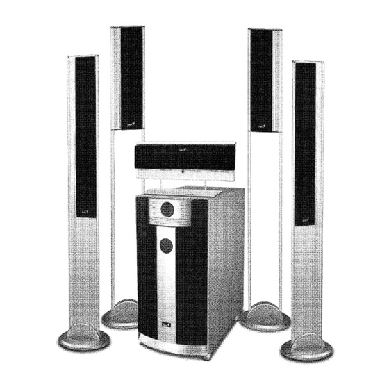
Service Manual Chapter 1. INTRODUCTION Function Block Decoder PCBA Signal input Main board Rear speakers Front speakers AMP PCBA Subwoofer POWER PCBA Transformer Center speaker Version 1.0 Page 2... -
Page 4: Chapter 2. Troubleshooting Guide
Service Manual Chapter 2. Troubleshooting Guide Problems Condition Probable Reasons Solutions 1.no power 1.power cable 1.cable broken 1.replace power cable 2.fuse 1.fuse broken 1.replace fuse 3.PCBA 1.center PCBA NG 1.replace center PCBA 2.power PCBA NG 1.replace power PCBA 3.Decoder PCBA NG 1.replace Decoder PCBA 2.display L.E.D. -
Page 5: Chapter 3. Removal And Replacement
Service Manual Chapter 3. Removal and Replacement Disassemble & Assemble the Fuse Step 1 Use a screwdriver to turn counterclockwise and open the fuse’s cap. Fuse Step 2 Get the Fuse and replace it with the same rate. Step 3 To install the Fuse, reverse the steps shown above. -
Page 6: Disassemble & Assemble The Rear Cover
Service Manual Disassemble & Assemble the Rear Cover Step 1 Using a screwdriver to loose 12 screws. After taking all screws off, you can take up the Rear cover. To install the rear cover, reverse the steps shown above. Version 1.0 Page 5... -
Page 7: Disassemble & Assemble Amplifier Pcba (Sub)
Service Manual Disassemble & Assemble Amplifier PCBA (SUB) Step 1 *Disassemble the Rear Cover first. Disconnect the cables & wires *Mark the position of cables & wires Step 2 To loose 2 screws.(A & B) Step 3 To loose 2 screws. After taking all screws off, you can take up the Amplifier PCBA *To install the Amplifier PCBA, reverse the steps shown above. -
Page 8: Disassemble & Assemble The Power Supply Pcba
Service Manual Disassemble & Assemble the Power Supply PCBA Step 1 *Disassemble the Rear Cover first. Cable Disconnect the cable. Step 2 To loose 8 screws. Form A-H. Step 3 To loose 4 screws. Form I-L. Step 4 Unsolder the wires on Power Supply PCBA. - Page 9 Service Manual Step 5 Unsolder the wires on Power Supply PCBA. And remove the wires. *Mark the position of wires Step 6 Disconnect the 3 cables. *To install the Power Supply PCBA, reverse the steps shown above. Grey White Version 1.0 Page 8...
-
Page 10: Disassemble & Assemble The Decoder Board
Service Manual Disassemble & Assemble the Decoder board Step 1 Remove the main board. Step 2 Use tweezers to remove the fixed glue. And then use your hands to separate decoder board from main board. *To install the decoder board, reverse the steps shown above. -
Page 11: Chapter 4. Testing Procedures
Service Manual Chapter 4. Testing Procedures Step 1 Connecting the GHT-511D to a DVD or VCD player. Play a DVD disk on it. Step 2 Power on the GHT-511D. The monitor should display ‘321’ then ‘0db’. LED display ‘C’, ’L’, ’C’, ’SUB’, ’LS’, ’RS’, ’Digital’, ’Coaxial’, ’Lock’. -
Page 12: Chapter 5. Important Notes
Service Manual Chapter 5. Important Notes Packing requirement for sending the PCB assembly PCB assembly is a kind of sophisticated electronic circuit board. Therefore, well packing will be required when sending them by post or courier. Some sophisticated IC components are mounted on the PCB assembly, hence it is necessary to pack each PCB assembly with a separate static protecting beg, in order to avoid static electricity. -
Page 13: Chapter 6. Parts List (Vender's Number)
Service Manual Chapter 6. Parts list (Vender’s number) Item Part number description Position J66-01236-000 PCBA AMP J66-01236-400 PCBA CENTER AMP J66-01335-000 PCBA POWER J66-01335-010 PCBA VOLUME CONTROL J83-005AA-U00 FUSE 125V/5A SLOW BLOW J51-00002-03 NJM4558DD J53-00001-02 Diode 1N4148 J51-01054-000 IC TDA7296 60W J52-21001-000 Resonator 4MHZ J51-01011-000... -
Page 14: Chapter 7. Tools
Service Manual Chapter 7. Tools VCD or DVD Player MUSIC CD or DVD Soldering-Iron (40W) Tweezers Screwdriver Pliers Multimeter Glue-heater Version 1.0 Page 13...
Need help?
Do you have a question about the GHT-511D and is the answer not in the manual?
Questions and answers