Table of Contents
Advertisement
Advertisement
Chapters
Table of Contents

Related Manuals for Asus Z97-K/USB3.1


Summary of Contents for Asus Z97-K/USB3.1
- Page 1 Z97-K/USB 3.1...
- Page 2 Product warranty or service will not be extended if: (1) the product is repaired, modified or altered, unless such repair, modification of alteration is authorized in writing by ASUS; or (2) the serial number of the product is defaced or missing.
-
Page 3: Table Of Contents
My Favorites ................2-15 Main menu .................. 2-17 Ai Tweaker menu ................ 2-19 Advanced menu ................. 2-31 Monitor menu ................2-41 Boot menu .................. 2-45 Tool menu ................... 2-51 2.10 Exit menu ..................2-52 Appendices Notices .......................A-1 ASUS contact information ...............A-4... -
Page 4: Safety Information
Safety information Electrical safety • To prevent electrical shock hazard, disconnect the power cable from the electrical outlet before relocating the system. • When adding or removing devices to or from the system, ensure that the power cables for the devices are unplugged before the signal cables are connected. If possible, disconnect all power cables from the existing system before you add a device. -
Page 5: Conventions Used In This Guide
Refer to the following sources for additional information and for product and software updates. ASUS websites The ASUS website provides updated information on ASUS hardware and software products. Refer to the ASUS contact information. Optional documentation Your product package may include optional documentation, such as warranty flyers, that may have been added by your dealer. -
Page 6: Package Contents
* Hyper DIMM support is subject to the physical characteristics of individual CPUs. Please refer to Memory QVL (Qualified Vendors List) for details. ** Refer to www.asus.com for the Memory QVL (Qualified Vendors List). 1 x PCI Express 3.0/2.0 x16 slot (at x16 mode) Expansion slots 1 x PCI Express 2.0 x16 slot (max at x2 mode) - Page 7 * Use a chassis with HD audio module in the front panel to support an 8-channel audio output Intel Z97 Express Chipset - supports ASUS USB 3.1 Boost ® - 2 x USB 3.1/3.0/2.0 ports (2 ports at the back panel, teal blue) - 4 x USB 3.0/2.0 ports (2 ports at midboard, 2 ports at the back...
- Page 8 - ASUS ESD Guards - Enhanced ESD protection - ASUS High-Quality 5K-Hour Solid Capacitors - 2.5x long lifespan with excellent durability - ASUS Stainless Steel Back I/O - 3x more durable corrosion-resistant coatin UEFI BIOS - Most advanced options with fast response time M.2 onboard...
- Page 9 Z97-K/USB 3.1 specifications summary ASUS quiet thermal Quiet Thermal Design solution - ASUS Fan Xpert 2+ - Stylish Fanless Design: PCH Heat-sink & MOS Heat-sink solution Precision Tweaker 2 ASUS exclusive overclocking features - vCore: Adjustable CPU Core voltage at 0.001V increment - iGPU: Adjustable CPU Graphics voltage at 0.001V increment...
- Page 10 64 Mb Flash ROM, UEFI AMI BIOS, PnP, DMI 2.7, WfM 2.0, SM BIOS BIOS features 2.8.0, ACPI 5.0, Multi-language BIOS, ASUS EZ Flash 2, CrashFree BIOS 3, F11 EZ Tuning Wizard, F6 Qfan Control, F3 My Favorites, Quick Note, Last Modified Log, F12 PrintScreen function, F3 Shortcut function,...
-
Page 11: Chapter 1: Product Introduction
• Unplug the power cord from the wall socket before touching any component. • Before handling components, use a grounded wrist strap or touch a safely grounded object or a metal object, such as the power supply case, to avoid damaging them due to static electricity. • Hold components by the edges to avoid touching the ICs on them. • Whenever you uninstall any component, place it on a grounded antistatic pad or in the bag that came with the component. • Before you install or remove any component, ensure that the ATX power supply is switched off or the power cord is detached from the power supply. Failure to do so may cause severe damage to the motherboard, peripherals, or components. ASUS Z97-K/USB 3.1... -
Page 12: Motherboard Overview
Motherboard overview Before you install the motherboard, study the configuration of your chassis to ensure that the motherboard fits. Unplug the power cord before installing or removing the motherboard. Failure to do so can cause you physical injury and damage to motherboard components. 1.2.1 Placement direction When installing the motherboard, place it into the chassis in the correct orientation. The edge with external ports goes to the rear part of the chassis as indicated in the image. 1.2.2 Screw holes Place six screws into the holes indicated by circles to secure the motherboard to the chassis. Do not overtighten the screws! Doing so can damage the motherboard. -
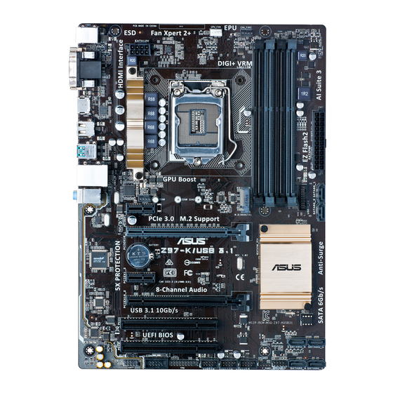
Page 13: Motherboard Layout
1442K LGA1150 USB7/8 USB 3.1 _E12 LAN_USB3_56 CHA_FAN1 AUDIO 1142 PCIEX1_1 PCIEX16_1 8111GR Z97-K/USB 3.1 BATTERY Intel ® 1083 PCIEX1_2 PCIEX16_2 Super BIOS PCI1 PCI2 SATA6G_6 SATA6G_5 CLRTC SATA6G_4 SATA6G_3 SPDIF_OUT USB910 USB1112 USB1314 F_PANEL SPEAKER AAFP ASUS Z97-K/USB 3.1... -
Page 14: Central Processing Unit (Cpu)
1.2.4 Layout contents Connectors/Jumpers/Slots/LED Page 1. CPU and chassis fan connectors (4-pin CPU_FAN, 4-pin CHA_FAN1/2) 1-15 2. ATX power connectors (24-pin EATXPWR, 8-pin EATX12V) 1-19 3. LGA1150 CPU socket 4. DDR3 DIMM slots 5. USB 3.0 connector (20-1 pin USB3_12) 1-22 6. Intel Z97 Serial ATA 6.0 Gb/s connectors (7-pin SATA6G_1-6) 1-17 ® 7. M.2 Socket 3 1-22 8. Clear RTC RAM (3-pin CLRTC) 1-12 9. System panel connector (10-1 pin PANEL) 1-21 10. Speaker connector (4-pin SPEAKER) 1-19 11. USB 2.0 connectors (10-1 pin USB910, USB1112, USB1314) 1-20 12. TPM connector (20-1 pin TPM) 1-18 13. -
Page 15: Z97-K/Usb
• Upon purchase of the motherboard, ensure that the PnP cap is on the socket and the socket contacts are not bent. Contact your retailer immediately if the PnP cap is missing, or if you see any damage to the PnP cap/socket contacts/motherboard components. ASUS will shoulder the cost of repair only if the damage is shipment/ transit-related. • Keep the cap after installing the motherboard. ASUS will process Return Merchandise Authorization (RMA) requests only if the motherboard comes with the cap on the LGA1150 socket. • The product warranty does not cover damage to the socket contacts resulting from incorrect CPU installation/removal, or misplacement/loss/incorrect removal of the PnP cap. 1.3.1 Installing the CPU ASUS Z97-K/USB 3.1... -
Page 16: Cpu Heatsink And Fan Assembly Installation
1.3.2 CPU heatsink and fan assembly installation Apply the Thermal Interface Material to the CPU heatsink and CPU before you install the heatsink and fan if necessary. To install the CPU heatsink and fan assembly Chapter 1: Product introduction... -
Page 17: System Memory
To uninstall the CPU heatsink and fan assembly System memory 1.4.1 Overview This motherboard comes with four Double Data Rate 3 (DDR3) Dual Inline Memory Module (DIMM) sockets. The figure illustrates the location of the DDR3 DIMM sockets: Channel Sockets Channel A DIMM_A1 and DIMM_A2 Channel B DIMM_B1 and DIMM_B2 Z97-K/USB 3.1 Z97-K/USB 3.1 240-pin DDR3 DIMM sockets ASUS Z97-K/USB 3.1... -
Page 18: Memory Configurations
OS. ® I nstall a 64-bit Windows OS if you want to install 4GB or more on the ® motherboard. F or more details, refer to the Microsoft support site at http://support.microsoft. ® com/kb/929605/en-us. • This motherboard does not support DIMMs made up of 512 megabits (Mb) chips or less. • The default memory operation frequency is dependent on its Serial Presence Detect (SPD), which is the standard way of accessing information from a memory module. Under the default state, some memory modules for overclocking may operate at a lower frequency than the vendor-marked value. To operate at the vendor-marked or at a higher frequency, refer to section 2.5 Ai Tweaker menu for manual memory frequency adjustment. • For system stability, use a more efficient memory cooling system to support a full memory load (4 DIMMs) or overclocking condition. • Visit the ASUS website at: www.asus.com for the latest QVL. Chapter 1: Product introduction... -
Page 19: Installing A Dimm
1.4.3 Installing a DIMM To install a DIMM To remove a DIMM ASUS Z97-K/USB 3.1... -
Page 20: Expansion Slots
Expansion slots In the future, you may need to install expansion cards. The following sub-sections describe the slots and the expansion cards that they support. Unplug the power cord before adding or removing expansion cards. Failure to do so may cause you physical injury and damage motherboard components. 1.5.1 Installing an expansion card To install an expansion card: Before installing the expansion card, read the documentation that came with it and make the necessary hardware settings for the card. Remove the system unit cover (if your motherboard is already installed in a chassis). - Page 21 PCI_1 – – – shared – – – – PCI_2 shared – – – – – – – Asmedia – – – – – – – – U3.1 shared – – – – – – – ASUS Z97-K/USB 3.1 1-11...
-
Page 22: Jumpers
Jumpers Clear RTC RAM (3-pin CLRTC) This jumper allows you to clear the Real Time Clock (RTC) RAM in CMOS. You can clear the CMOS memory of date, time, and system setup parameters by erasing the CMOS RTC RAM data. The onboard button cell battery powers the RAM data in CMOS, which include system setup information such as system passwords. CLRTC Z97-K/USB 3.1 Normal Clear RTC (Default) Z97-K/USB 3.1 Clear RTC RAM To erase the RTC RAM: Turn OFF the computer and unplug the power cord. Move the jumper cap from pins 1-2 (default) to pins 2-3. Keep the cap on pins 2-3 for about 5-10 seconds, then move the cap back to pins 1-2. Plug the power cord and turn ON the computer. Hold down the <Del> key during the boot process and enter BIOS setup to re- enter data. Except when clearing the RTC RAM, never remove the cap on CLRTC jumper default position. Removing the cap will cause system boot failure! • If the steps above do not help, remove the onboard battery and move the jumper again to clear the CMOS RTC RAM data. After clearing the CMOS, reinstall the battery. •... -
Page 23: Connectors
1Gbps connection (Blinking) LAN port Orange Ready to (Blinking then wake up from steady) S5 mode Line In port (light blue). This port connects to the tape, CD, DVD player, or other audio sources. Line Out port (lime). This port connects to a headphone or a speaker. In the 4.1, 5.1, and 7.1-channel configurations, the function of this port becomes Front Speaker Out. Microphone port (pink). This port connects to a microphone. Refer to the audio configuration table on the next page for the function of the audio ports in 2.1, 4.1, 5.1, or 7.1-channel configuration. ASUS Z97-K/USB 3.1 1-13... - Page 24 Audio 2.1, 4.1, 5.1, or 7.1-channel configuration Headset Port 4.1-channel 5.1-channel 7.1-channel 2.1-channel Light Blue (Rear Line In Rear Speaker Out Rear Speaker Out Rear Speaker Out panel) Lime (Rear panel) Line Out Front Speaker Out Front Speaker Out Front Speaker Out Pink (Rear panel) Mic In Mic In Bass/Center Bass/Center Pink (Front panel) – – – Side Speaker Out To configure a 7.1-channel audio output: Use a chassis with HD audio module in the front panel to support a 7.1-channel audio output.
-
Page 25: Serial Port Connector (10-1 Pin Com)
CPU and chassis fan connectors (4-pin CPU_FAN, and 4-pin CHA_FAN1/2) Connect the fan cables to the fan connectors on the motherboard, ensuring that the black wire of each cable matches the ground pin of the connector. CPU_FAN CHA_FAN2 CHA_FAN1 Z97-K/USB 3.1 Z97-K/USB 3.1 Fan connectors • DO NOT forget to connect the fan cables to the fan connectors. Insufficient air flow inside the system may damage the motherboard components. These are not jumpers! DO NOT place jumper caps on the fan connectors. • Ensure that the CPU fan cable is securely installed to the CPU fan connector. ASUS Z97-K/USB 3.1 1-15... -
Page 26: Front Panel Audio Connector (10-1 Pin Aafp)
• The CPU_FAN connector supports the CPU fan of maximum 1A (12 W) fan power. • The CPU_FAN and CHA_FAN connectors support the ASUS FAN Xpert 2+ feature. • The chassis fan connectors support DC and PWM modes. To set these fans to DC or PWM, go to Advanced Mode > Monitor > Chassis Fan 1/2 Q-Fan Control items in BIOS. Front panel audio connector (10-1 pin AAFP) This connector is for a chassis-mounted front panel HD audio I/O module. Connect one end of the front panel audio I/O module cable to this connector. AAFP PIN 1 PIN 1 Z97-K/USB 3.1 HD-audio-compliant Legacy AC’97 pin definition compliant definition Z97-K/USB 3.1 Front panel audio connector... -
Page 27: Intel ® Z97 Serial Ata 6.0 Gb/S Connectors (7-Pin Sata6G_1-6)
Z97-K/USB 3.1 Intel SATA 6 Gb/s connectors ® • These connectors are set to [AHCI] by default. If you intend to create a Serial ATA RAID set using these connectors, set the SATA Mode Selection item in the BIOS to [RAID]. See section 2.6.3 PCH Storage Configuration for details. • Before creating a RAID set, refer to the RAID Supplementary Guide included in the folder named Manual in the support DVD. • When using hot-plug and NCQ, set the SATA Mode Selection item in the BIOS to [AHCI]. M.2 Socket 3 shares the bandwidth with SATA ports 5 and 6. To ensure that the M.2 PCIe device is working properly, SATA ports 5 and 6 are disabled. See section 2.6.3 PCH Storage Configuration of this user guide for more details. ASUS Z97-K/USB 3.1 1-17... -
Page 28: Tpm Connector (20-1 Pin Tpm)
Digital audio connector (4-1 pin SPDIF_OUT) This connector is for an additional Sony/Philips Digital Interface (S/PDIF) port. Connect the S/PDIF Out module cable to this connector, then install the module to a slot opening at the back of the system chassis. Z97-K/USB 3.1 PIN 1 SPDIF_OUT Z97-K/USB 3.1 Digital audio connector The S/PDIF module is purchased separately. TPM connector (20-1 pin TPM) This connector supports a Trusted Platform Module (TPM) system, which can securely store keys, digital certificates, passwords, and data. A TPM system also helps enhance network security, protects digital identities, and ensures platform integrity. PIN 1 Z97-K/USB 3.1 Z97-K/USB 3.1 TPM connector The TPM module is purchased separately. -
Page 29: Atx Power Connectors (24-Pin Eatxpwr, 8-Pin Eatx12V)
Speaker connector (4-pin SPEAKER) The 4-pin connector is for the chassis-mounted system warning speaker. The speaker allows you hear system beeps and warnings. SPEAKER Z97-K/USB 3.1 PIN 1 Z97-K/USB 3.1 Speaker Out connector ASUS Z97-K/USB 3.1 1-19... -
Page 30: Usb 2.0 Connectors (10-1 Pin Usb910, Usb1112, Usb1314)
USB 2.0 connectors (10-1 pin USB910; USB1112; USB1314) These connectors are for USB 2.0 ports. Connect the USB module cable to any of these connectors, then install the module to a slot opening at the back of the system chassis. These USB connectors comply with USB 2.0 specification that supports up to 480 Mbps connection speed. USB910 USB1112 USB1314 Z97-K/USB 3.1 PIN 1 PIN 1 PIN 1 Z97-K/USB 3.1 USB2.0 connectors Never connect a 1394 cable to the USB connectors. Doing so will damage the motherboard! The USB 2.0 module is purchased separately. 1-20 Chapter 1: Product introduction... -
Page 31: System Panel Connector
Pressing the power switch for more than four seconds while the system is ON turns the system OFF. • Reset button (2-pin RESET) This 2-pin connector is for the chassis-mounted reset button for system reboot without turning off the system power. ASUS Z97-K/USB 3.1 1-21... -
Page 32: Usb 3.0 Connector (20-1 Pin Usb3_12)
IntA_P1_SSTX+ IntA_P2_SSTX+ IntA_P1_D- IntA_P2_D- IntA_P1_D+ IntA_P2_D+ Z97-K/USB 3.1 USB3.0 Front panel connector • The USB 3.0 module is purchased separately. • You can connect the ASUS front panel USB 3.0 bracket to this connector. M.2 Socket 3 This socket allows you to install an M.2 (NGFF) SSD module. SCOKET3 Z97-K/USB 3.1 Z97-K/USB 3.1 M.2 socket • This socket supports M Key and type 2242/2260/2280 storage devices. • The M.2 Socket 3 shares bandwidth with SATA6G_5 and SATA6G_6. Refer to section 2.6.3 PCH Storage Configuration of this user guide for more details. -
Page 33: Software Support
The Support DVD that comes with the motherboard package contains the drivers, software applications, and utilities that you can install to avail all motherboard features. The contents of the Support DVD are subject to change at any time without notice. Visit the ASUS website at www.asus.com for updates. To run the Support DVD Place the Support DVD into the optical drive. If Autorun is enabled in your computer, the DVD automatically displays the Specials screen which lists the unique features of your ASUS motherboard. Click Drivers, Utilities, AHCI/RAID Driver, Manual, Contact, and Specials tabs to display their respective menus. The following screen is for reference only. Click an icon to display Support DVD/motherboard information Click an item to install If Autorun is NOT enabled in your computer, browse the contents of the Support DVD to locate the file ASSETUP.EXE from the BIN folder. Double-click the ASSETUP.EXE to run the DVD. ASUS Z97-K/USB 3.1 1-23... - Page 34 1-24 Chapter 1: Product introduction...
-
Page 35: Chapter 2: Bios Information
Managing and updating your BIOS Save a copy of the original motherboard BIOS file to a USB flash disk in case you need to restore the BIOS in the future. Copy the original motherboard BIOS using the ASUS Update utility. -
Page 36: Asus Ez Flash
2.1.2 ASUS EZ Flash 2 The ASUS EZ Flash 2 feature allows you to update the BIOS without using an OS‑based utility. Before you start using this utility, download the latest BIOS file from the ASUS website at www.asus.com. To update the BIOS using EZ Flash 2: Insert the USB flash disk that contains the latest BIOS file to the USB port. -
Page 37: Asus Crashfree Bios 3 Utility
2.1.3 ASUS CrashFree BIOS 3 utility The ASUS CrashFree BIOS 3 is an auto recovery tool that allows you to restore the BIOS file when it fails or gets corrupted during the updating process. You can restore a corrupted BIOS file using the motherboard support DVD or a USB flash drive that contains the updated BIOS file. - Page 38 ENTER to select boot device ESC to boot using defaults P2: ST3808110AS (76319MB) aigo miniking (250MB) UEFI: (FAT) ASUS DRW-2014L1T(4458MB) P1: ASUS DRW-2014L1T(4458MB) UEFI: (FAT) aigo miniking (250MB) Enter Setup When the booting message appears, press <Enter> within five (5) seconds to enter FreeDOS prompt.
- Page 39 DO NOT shut down or reset the system while updating the BIOS to prevent system boot failaure. Ensure to load the BIOS default settings to ensure system compatibility and stability. Select the Load Optimized Defaults item under the Exit BIOS menu. See section 2.10 Exit Menu for details. ASUS Z97-K/USB 3.1...
-
Page 40: Bios Setup Program
The BIOS setup screens shown in this section are for reference purposes only, and may not exactly match what you see on your screen. • Visit the ASUS website at www.asus.com to download the latest BIOS file for this motherboard. •... - Page 41 Click the button to manually Selects the boot Saves the changes tune the fans device priority and resets the Loads optimized system default settings The boot device options vary depending on the devices you installed to the system. ASUS Z97-K/USB 3.1 2‑7...
-
Page 42: Advanced Mode
2.2.2 Advanced Mode The Advanced Mode provides advanced options for experienced end‑users to configure the BIOS settings. The figure below shows an example of the Advanced Mode. Refer to the following sections for the detailed configurations. To access the EZ Mode, click EzMode(F7) or press <F7>. Q-Fan control EZ Tuning Wizard... -
Page 43: Menu Bar
This button above the menu bar allows you to view and tweak the overclocking settings of your system. It also allows you to change the motherboard’s SATA mode from AHCI to RAID mode. Refer to section 2.2.4 EZ Tuning Wizard for more information. ASUS Z97-K/USB 3.1... -
Page 44: Hot Keys
Quick Note (F9) This button above the menu bar allows you to key in notes of the activities that you have done in BIOS. • The Quick Note function does not support the following keyboard functions: delete, cut, copy and paste. •... -
Page 45: Qfan Control
Click to activate DC Click to activate to be configured Mode PWM Mode Select a profile to apply Click to apply to your fans the fan setting Click to undo Click to the changes go back to main menu ASUS Z97-K/USB 3.1 2-11... - Page 46 Configuring fans manually Select Manual from the list of profiles to manually configure your fans’ operating speed. Click to manually Speed points configure your fans To configure your fans: Select the fan that you want to configure and to view its current status. Click and drag the speed points to adjust the fans’...
-
Page 47: Ez Tuning Wizard
Select the CPU fan type (Box cooler, Tower cooler, or Water cooler) that you installed then click Next. If you are not sure of the CPU fan type, click I’m not sure. The system automatically detects the CPU fan type. Click Next then click Yes to confirm auto‑tuning. ASUS Z97-K/USB 3.1 2‑13... -
Page 48: Creating Raid
Creating RAID To create RAID: Press <F11> on your keyboard or click from the BIOS screen to open EZ Tuning Wizard screen. Click RAID then click Next. • Ensure that your HDDs have no existing RAID volumes. • Ensure to connect your HDDs to Intel SATA connectors. -
Page 49: My Favorites
My Favorites MyFavorites is your personal space where you can easily save and access your favorite BIOS items. ASUS Z97-K/USB 3.1 2-15... - Page 50 Adding items to My Favorites To add BIOS items: Press <F3> on your keyboard or click from the BIOS screen to open Setup Tree Map screen. On the Setup Tree Map screen, select the BIOS items that you want to save in MyFavorites screen.
-
Page 51: Main Menu
RAM to clear the BIOS password. See section 1.6 Jumpers for information on how to erase the RTC RAM. • The Administrator or User Password items on top of the screen show the default Not Installed. After you set a password, these items show Installed. ASUS Z97-K/USB 3.1 2‑17... -
Page 52: Administrator Password
Administrator Password If you have set an administrator password, we recommend that you enter the administrator password for accessing the system. To set an administrator password: Select the Administrator Password item and press <Enter>. From the Create New Password box, key in a password, then press <Enter>. Confirm the password when prompted. -
Page 53: Ai Tweaker Menu
The following five items appear only when you set the Ai Overclocking Tuner to [Manual]. CPU Strap [Auto] Manually select a strap value that is close to the target BCLK frequency for extreme overclocking. Configuration options: [Auto] [100MHz] [125MHz] [167MHz] [250MHz] ASUS Z97-K/USB 3.1 2-19... - Page 54 BCLK Frequency. 2.5.2 ASUS MultiCore Enhancement [Auto] [Auto] This item allows you to maximize the oveclocking performance optimized by ASUS core ratio settings. [Disabled] This item allows you to set to default core ratio settings. 2.5.3 CPU Core Ratio [Auto] This item allows you to set the CPU core ratio limit per core or synchronize automatically to all cores.
- Page 55 Allows you to set the CPU bus speed to DRAM speed ratio mode. [Auto] DRAM speed is set to the optimized settings. [100:133] The BCLK frequency to DRAM speed ratio is set to 100:133. [100:100] The BCLK frequency to DRAM speed ratio is set to 100:100. ASUS Z97-K/USB 3.1 2-21...
-
Page 56: Dram Timing Control
2.5.12 EPU Power Saving Mode [Disabled] ASUS EPU (Energy Processing Unit) sets the CPU in its minimum power consumption settings. Enable this item to set lower CPU VCCIN and Vcore voltages and achieve the best energy saving condition. Configuration options: [Disabled] [Enabled] 2.5.13... - Page 57 CPU Power Duty Control [T.Probe] DIGI + VRM Duty control adjusts the current and thermal conditions of every component’s phase. [T. Probe] Select to maintain the VRM thermal balance. [Extreme] Select to maintain the current VRM balance. ASUS Z97-K/USB 3.1 2‑23...
- Page 58 CPU Current Capability [Auto] Allows you to configure the total power range, and extends the overclocking frequency range simultaneously. Configuration options: [Auto] [100%] [110%] [120%] [130%] [140%] Choose a higher value when overclocking, or under a high CPU loading for extra power support.
- Page 59 This item allows you to increase or decrease the output current sensed by the CPU. It finds the balance between optimal regulating while staying below the current threshold. Configuration options: [Auto] [100%] [87.5%] [75.0%] [62.5%] [50.0%] [37.5%] [25.0%] [12.5%] [0%] [‑12.5%] [‑25.0%] [‑37.5%] [‑50.0%] [‑62.5%] [‑75.0%] [‑87.5%] [‑100%] ASUS Z97-K/USB 3.1 2-25...
-
Page 60: Offset Mode Sign
Power Fast Ramp Response [Auto] This item allows you to enhance the response of the CPU voltage regulator during the load transients. Use the <+> or <‑> to adjust the value. The values range from 0.00 to 1.50. Configuration options: [Auto] [0.00] ‑ [1.50] CPU Internal Power Saving Control Power Saving Level 1 Threshhold [Auto] Lower value provides sufficient overclocking tolerance to enlarge the overclocking... - Page 61 Increase the voltage when configuring a high CPU core frequency. The voltage you set is affected by the offset value. Use the <+> or <‑> keys to adjust the value. The values range from 0.001V to 1.920V with a 0.001V interval. ASUS Z97-K/USB 3.1 2‑27...
- Page 62 Total Adaptive Mode CPU Cache Voltage [Auto] This item sums up the voltages of the CPU Cache Voltage offset and Additional Turbo Mode CPU Cache Voltage options. 2.5.19 CPU Graphics Voltage [Auto] This item allows you to set the CPU graphics voltage. Increase the graphics voltage when increasing the iGPU frequency.
- Page 63 The values range from 1.1850V to 1.8000V with a 0.0050V interval. According to Intel CPU specifications, DIMMs with voltage requirement over 1.65V may damage the CPU permanently. We recommend that you install the DIMMs with the voltage requirement below 1.65V. ASUS Z97-K/USB 3.1 2-29...
- Page 64 2.5.25 PCH VLX Voltage [Auto] This item allows you to set the I/O voltage on the PCH (Platform Controller Hub). You can use the <+> or <‑> keys to adjust the value. The values range from 1.1850V to 2.1350V with a 0.0050V interval.
-
Page 65: Advanced Menu
This item allows you to protect the CPU by decreasing its frequency as it reaches the thermal throttle point. The thermal monitor includes TM1 (Thermal monitor 1), TM2 (Thermal monitor 2), and EMTTM (Enhanced Multi‑threaded Thermal Monitoring). Configuration options: [Disabled] [Enabled] ASUS Z97-K/USB 3.1 2‑31... -
Page 66: Cpu Power Management Configuration
Active Processor Cores [All] This item allows you to select the number of CPU cores to activate in each processor package. Configuration options: [All] [1] [2] [3] For some CPU types, only [All] and [1] appear. Limit CPUID Maximum [Disabled] When set to [Enabled], this item allows the legacy OS to boot even without support for CPUs with extended CPUID functions. - Page 67 This item allows you to set the duration of C7 latency for C7 state. Configuration options: [Short] [Long] Package C State Support [Auto] This item allows you to set the a C‑state support for the CPU package. Configuration options: [Auto] [Enabled] [C0/C1] [C2] [C3] [C6] [CPU C7] [CPU C7s] ASUS Z97-K/USB 3.1 2‑33...
-
Page 68: Pch Configuration
2.6.2 PCH Configuration PCI Express Configuration This item allows you to configure the PCI Express slots. PCI-E Speed [Auto] This item allows your system to automatically select the PCI Express port speed. When set to [Gen1], the PCI‑E port runs at PCI‑E 1.0 speed. When set to [Gen2], the PCI‑E port runs at PCI‑E 2.0 speed. -
Page 69: Pch Storage Configuration
POST (Power‑on Self Test) when an error occurs in the hard disks. Configuration options: [On] [Off] Hot Plug [Disabled] (SATA6G_1 (Gray) ~ SATA6G_6(Gray)) These items allow you to enable/disable SATA Hot Plug Support. Configuration options: [Disabled] [Enabled] ASUS Z97-K/USB 3.1 2‑35... -
Page 70: System Agent Configuration
2.6.4 System Agent Configuration VT-d [Disabled] Allows you to enable or disable VT‑d function on MCH. Configuration options: [Enabled] [Disabled] CPU Display Audio [Enabled] Enable this item to support CPU display audio output. Configuration options: [Enabled] [Disabled] DVI Port Audio [Off] Enable this item to support audio output for certain DVI monitors. -
Page 71: Usb Configuration
This item allows you to enable or disable the individual USB ports. USB Single Port Control This item allows you to enable or disable the individual USB ports. Refer to section 1.2.3 Motherboard layout for the location of the USB ports. ASUS Z97-K/USB 3.1 2‑37... -
Page 72: Platform Misc Configuration
ASPM to take effect. Configuration options: [Disabled] [L0s] [L1] [L0sL1] PEG ASPM Support [Disabled] This item allows you to select the ASPM state for energy‑saving conditions, or use the ASUS optimized energy saving profile. Configuration options: [Disabled] [Auto] [ASPM L0s] [L1] [L0sL1] 2.6.7... - Page 73 Realtek PXE Option ROM [Disabled] This item appears only when you set the previous item to [Enabled] and allows you to enable or disable the PXE OptionRom of the Realtek LAN controller. Configuration options: [Enabled] [Disabled] ASUS Z97-K/USB 3.1 2‑39...
-
Page 74: Serial Port Configuration
Serial Port Configuration The sub‑items in this menu allow you to set the serial port configuration. Serial Port [Enabled] Allows you to enable or disable the serial port (COM).Configuration options: [Enabled] [Disabled] Change Settings [IO=3F8h; IRQ=4] This item appears only when you set the Serial Port to [Enabled] and allows you to select the Serial Port base address. -
Page 75: Monitor Menu
This item allows you to enable or disable the Ipv4/Ipv6 PXE wake event. Configuration options: [Disabled] [Enabled] Monitor menu The Monitor menu displays the system temperature/power status, and allows you to change the fan settings. Scroll down to display the other BIOS items. ASUS Z97-K/USB 3.1 2-41... - Page 76 2.7.1 CPU/ MB Temperature [xxxºC/xxxºF]/ [Ignore] The onboard hardware monitor automatically detects and displays the CPU and motherboard temperatures. Select [Ignore] if you do not wish to display the detected temperatures. 2.7.2 CPU Fan/ Chassis Fan 1/2 Speed [xxxx RPM]/ [Ignore]/ [N/A] The onboard hardware monitor automatically detects and displays the CPU and chassis fan 1/2 speeds in rotations per minute (RPM).
- Page 77 The following four items appear only when you set Chassis Fan 1/2 Profile to [Manual]. Chassis Fan 1/2 Upper Temperature [70] Use the <+> or <‑> keys to adjust the upper limit of the CPU temperature. The values range from 40°C to 75°C. ASUS Z97-K/USB 3.1 2‑43...
- Page 78 Chassis Fan 1/2 Max. Duty Cycle(%) [100] Use the <+> or <‑> keys to adjust the maximum chassis fan duty cycle. The values range from 60% to 100%. When the chassis temperature reaches the upper limit, the chassis fan will operate at the maximum duty cycle. Chassis Fan 1/2 Middle Temperature [45] Use the <+>...
-
Page 79: Boot Menu
[Full Initialization] All USB devices will be available during POST. This process will extend the POST time. [Partial Initialization] For a faster POST time, only the USB ports with keyboard and mouse connections will be detected. ASUS Z97-K/USB 3.1 2-45... - Page 80 PS/2 Keyboard and Mouse Support [Auto] Select any of these settings when PS/2 keyboard and mouse are installed. These settings only apply when Fast Boot is enabled. [Auto] For a faster POST time, PS/2 devices will only be available when the system boots up or rebooted when the PS/2 devices have not been reconnected or changed.
- Page 81 Option ROM Messages [Enabled] [Enabled] The third‑party ROM messages will be displayed during POST. [Disabled] Disables the ROM messages and displays only the ASUS logo during POST. 2.8.6 Interrupt 19 Capture [Disabled] This item allows you to trap Interrupt 19 by the option ROMs. Configuration options: [Disabled] [Enabled] 2.8.7...
-
Page 82: Secure Boot
2.8.10 Secure Boot Allows you to configure the Windows Secure Boot settings and manage its keys to protect ® the system from unauthorized access and malwares during POST. OS Type [Windows UEFI mode] Allows you to select your installed operating system. [Windows UEFI mode] This item allows you to select your installed operating system. - Page 83 Allows you to delete the DBX file from your system. Doing so may expose the system to security threats. Load Default dbx Select Yes to load the system default dbx or select No to load a downloaded dbx from a USB storage device. ASUS Z97-K/USB 3.1 2-49...
-
Page 84: Boot Option Priorities
OS in Safe Mode, press <F8 > after POST (Windows 8 not supported). • To select the boot device during system startup, press <F8> when ASUS Logo appears. 2.8.12 Boot Override These items displays the available devices. The number of device items that appears on the screen depends on the number of devices installed in the system. -
Page 85: Tool Menu
<Enter> to display the submenu. 2.9.1 ASUS EZ Flash 2 Utility Allows you to run ASUS EZ Flash 2. Press [Enter] to launch the ASUS EZ Flash 2 screen. For more details, see section 2.1.2 ASUS EZ Flash 2. 2.9.2 Setup Animator [Enabled] Enables or disables the Setup animator. -
Page 86: Exit Menu
2.9.4 ASUS SPD Information DIMM Slot number [DIMM_A1] Displays the Serial Presence Detect (SPD) information of the DIMM module installed on the selected slot. Configuration options: [DIMM_A1] [DIMM_B1] [DIMM_A2] [DIMM_B2] 2.10 Exit menu The Exit menu items allow you to load the optimal default values for the BIOS items, and save or discard your changes to the BIOS items. -
Page 87: Appendices
Cet appareil est conforme aux normes CNR exemptes de licence d’Industrie Canada. Le fonctionnement est soumis aux deux conditions suivantes : (1) cet appareil ne doit pas provoquer d’interférences et (2) cet appareil doit accepter toute interférence, y compris celles susceptibles de provoquer un fonctionnement non souhaité de l’appareil. ASUS Z97-K/USB 3.1... -
Page 88: Canadian Department Of Communications Statement
ASUS Recycling/Takeback Services ASUS recycling and takeback programs come from our commitment to the highest standards for protecting our environment. We believe in providing solutions for you to be able to responsibly recycle our products, batteries, other components as well as the packaging materials. - Page 89 CE. das Diretivas da CE. Para mais detalhes, consulte a Declaração de Компания ASUS заявляет, что это устройство соответствует основным Conformidade CE. требованиям и другим соответствующим условиям европейских директив. Подробную информацию, пожалуйста, смотрите в декларации...
-
Page 90: Asus Contact Information
+1-510-739-3777 +1-510-608-4555 Web site http://www.asus.com/us/ Technical Support Support fax +1-812-284-0883 Telephone +1-812-282-2787 Online support http://www.service.asus.com/ ASUS COMPUTER GmbH (Germany and Austria) Address Harkort Str. 21-23, D-40880 Ratingen, Germany +49-2102-959911 Web site http://www.asus.com/de Online contact http://eu-rma.asus.com/sales Technical Support Telephone +49-1805-010923* Support Fax... - Page 91 ASUS Z97-K/USB 3.1...
Need help?
Do you have a question about the Z97-K/USB3.1 and is the answer not in the manual?
Questions and answers