
Related Manuals for Ampcontrol gasguard


Summary of Contents for Ampcontrol gasguard
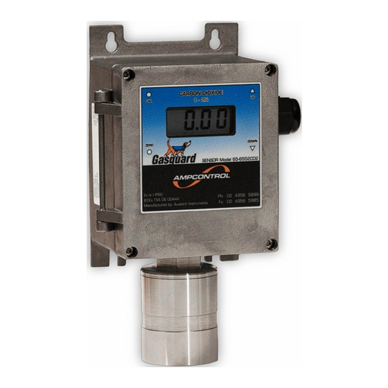
- Page 1 GASGUARD CO2 INFRARED TRANSMITTER / SENSOR UNITS User Manual Version: 2, APRIL 2016 Designed and manufactured in Australia by Ampcontrol Pty Ltd...
- Page 2 The note symbol highlights key information. Please share these notes with other operators. ENVIRO The enviro (environmental) symbol highlights areas which may have an impact on the surrounding fauna and/or flora. Uncontrolled Copy - Refer to Ampcontrol Website for Latest Version Page 2 of 26...
-
Page 3: Before You Begin
GSB048 Version 2 – APR/16 Copyright Notice The Ampcontrol device described in this document is the property of AMPCONTROL PTY LTD. It is furnished under a license agreement and is to be used only in accordance with the terms of the agreement. -
Page 4: Table Of Contents
7 SERVICE, MAINTENANCE & DISPOSAL ............24 7.1 Equipment Service ................... 24 7.2 Equipment Maintenance ................25 7.3 Disposal ....................25 8 SPECIFICATIONS ..................26 9 EQUIPMENT LIST ..................26 Uncontrolled Copy - Refer to Ampcontrol Website for Latest Version Page 4 of 26... - Page 5 Figure 5.1: CO2 IR Sensor / Transmitter Dimensions ......... 16 Figure 5.2: Integral Infrared Sensor Wiring Diagram ........... 18 Figure 5.3: Remote Infrared Sensor Wiring Diagram .......... 19 Figure 6.1: Gasguard CO2 IR Transmitter / Sensor Control Panel....................21 Figure 6.2: Gasguard CO2 IR Transmitter / Sensor Control Panel....................
-
Page 6: Safety And Other Warnings
As safety depends on the unit functioning correctly it is highly recommended that all safety functions of the unit be periodically tested to ensure correct operation. Uncontrolled Copy - Refer to Ampcontrol Website for Latest Version Page 6 of 26... -
Page 7: Receiving And Storage
Equipment that is found to be damaged or has been modified away from its published specification must not be used. Please contact Ampcontrol if the equipment is suspected to be different than that ordered or if it does not match the published specifications. -
Page 8: Unpacking Of Equipment
Where possible, dispose of all waste products i.e. oils, metals, plastic and rubber products by using an approved recycling service centre. Uncontrolled Copy - Refer to Ampcontrol Website for Latest Version Page 8 of 26... -
Page 9: Product Overview
GSB048 Version 2 – APR/16 3 PRODUCT OVERVIEW Ampcontrol’s Gasguard Infrared Carbon Dioxide Sensor / Transmitters are supplied complete with an amplifier and a Liquid Crystal Display. The Transmitter/Sensor assembly is an IEC Ex ia Group I certified assembly. The Certification is based on the unit being sealed to IP 66 and the appropriate checks being made on the Intrinsically Safe Parameters of the overall system the transmitter is connected into. -
Page 10: Amplifier Pcb
3.2 Amplifier PCB The purpose of the Amplifier PCB is to convert the low- level electrical output of the sensor into a signal capable of driving various types of external indicator equipment such as the Ampcontrol Gasguard 4 Channel Controller. -
Page 11: Figure 3.1: Anti-Vibration Clip
3.4.2 Anti-Vibration Clip An Anti-Vibration clip Pt/No. 121647 is fitted to the connectors J4 & J5 on the rear of the Amplifier PCB. Figure 3.1: Anti-Vibration Clip Uncontrolled Copy - Refer to Ampcontrol Website for Latest Version Page 11 of 26... -
Page 12: Product Operation
Amplifier needs reconfiguration Error has occurred Calibration mode initiated (display blinks when in calibration mode) Calibration settings have been saved PU/Ir Power Up – Infrared Unit Uncontrolled Copy - Refer to Ampcontrol Website for Latest Version Page 12 of 26... -
Page 13: Installation
5 INSTALLATION 5.1 General Warnings These instructions have been designed to assist users of the Gasguard CO2 IR Transmitter / Sensor with installation. Before the unit can be installed, there are a number of things that need to be considered and understood to prevent incorrect or unsafe operation of the unit or the system into which it is installed. -
Page 14: Mandatory Installation Practices
GSB048 Version 2 – APR/16 5.2 Mandatory Installation Practices The following information must be adhered to when installing the Gasguard CO2 IR Transmitter / Sensor. Failure to adhere to this information may give rise to unsafe operation. Using the unit in a manner that exceeds its electrical, functional or physical specifications, or in a way that is contrary to its operating restrictions, may create risks to personnel and/or equipment resulting in injury or death. -
Page 15: Table 3: Gas Density Relative To Air
Table 3: Gas Density Relative to Air Density Hydrogen Ammonia Lighter than Air Methane Carbon Monoxide Carbon Dioxide Nitric Oxide Oxygen Heavier than Air Hydrogen Sulphide Chlorine Nitrogen Dioxide Uncontrolled Copy - Refer to Ampcontrol Website for Latest Version Page 15 of 26... -
Page 16: Mechanical Installation Information
5.4.1 Enclosure Dimensions Figure 5.1: CO2 IR Sensor / Transmitter Dimensions 5.4.2 Mounting Arrangements The Gasguard CO2 IR Sensor / Transmitter is a panel mounted unit. See Figure 5.1 for hole centre locations. 5.4.3 Terminal Layout The connection terminals for the Gasguard CO2 IR Sensor / Transmitter are located within the enclosure. -
Page 17: Electrical Installation Information
Normal practice would be to isolate the cable screens at the Transmitter and connect the screens to earth adjacent to the Control units or power supply to the system. Remote sensor cable screens should be earthed at the transmitter. Uncontrolled Copy - Refer to Ampcontrol Website for Latest Version Page 17 of 26... -
Page 18: Figure 5.2: Integral Infrared Sensor Wiring Diagram
Ampcontrol Pty Ltd – ABN 28 000 915 542 GASGUARD CO2 IR SENSOR USER MANUAL GSB048 Version 2 – APR/16 5.5.3 Integral Infrared Sensor Unit Wiring Details Figure 5.2: Integral Infrared Sensor Wiring Diagram Uncontrolled Copy - Refer to Ampcontrol Website for Latest Version Page 18 of 26... -
Page 19: Figure 5.3: Remote Infrared Sensor Wiring Diagram
Ampcontrol Pty Ltd – ABN 28 000 915 542 GASGUARD CO2 IR SENSOR USER MANUAL GSB048 Version 2 – APR/16 5.5.4 Remote Infrared Sensor Unit Wiring Details Figure 5.3: Remote Infrared Sensor Wiring Diagram Uncontrolled Copy - Refer to Ampcontrol Website for Latest Version Page 19 of 26... -
Page 20: Commissioning And Calibration
Calibration gas should be applied to the sensor at a rate of approximately 0.5 to 1.0 litres per minute, using the Calibration Cup. Allow sufficient time, usually about 2 minutes, for sensor to stabilize before adjustment. Uncontrolled Copy - Refer to Ampcontrol Website for Latest Version Page 20 of 26... -
Page 21: Zero Calibration
Ampcontrol Pty Ltd – ABN 28 000 915 542 GASGUARD CO2 IR SENSOR USER MANUAL GSB048 Version 2 – APR/16 Figure 6.1: Gasguard CO2 IR Transmitter / Sensor Control Panel 6.3 Zero Calibration Perform Zero Calibration as follows: 1. Ensure that the sensor is in a fresh air environment, and apply High Purity Nitrogen via the Calibration Cup. -
Page 22: Span Calibration
Ampcontrol Pty Ltd – ABN 28 000 915 542 GASGUARD CO2 IR SENSOR USER MANUAL GSB048 Version 2 – APR/16 Figure 6.2: Gasguard CO2 IR Transmitter / Sensor Control Panel 6.4 Span Calibration Perform Span Calibration as follows: 1. Apply CO2 calibration gas to the sensor at the rate of 0.5 to 1 litres per minute. Use a calibration gas of suitable concentration between 1% to 2% CO2 for the 2% range unit or 2.5% to 5.0% for... -
Page 23: Calibration Troubleshooting
GASGUARD CO2 IR SENSOR USER MANUAL GSB048 Version 2 – APR/16 6.5 Calibration Troubleshooting If during calibration or zero of the Gasguard CO2 Transmitter the fault indication on the local display is shown as “ERR” then possible reasons are as follows: 6.5.1 Calibration Error If the fault code appears during calibration it will normally be when adjustment by the Up or Down arrows is attempted. -
Page 24: Service, Maintenance & Disposal
A number of external system based checks should be completed on a regular basis. These ‘routine inspections’ must be carried out by suitably trained people with knowledge of the Gasguard CO2 IR Transmitter / Sensor and the systems into which it is fitted. Routine inspections may take the form of either visual-only checks, or visual and ‘hands-on’... -
Page 25: Equipment Maintenance
By ensuring that this product is disposed of correctly you will be helping to prevent potentially negative consequences for the environment which could otherwise be caused by incorrect waste handling of this product. Uncontrolled Copy - Refer to Ampcontrol Website for Latest Version Page 25 of 26... -
Page 26: Specifications
141579 CO2 Sensor / Transmitter - 5% - 10 Metre Remote Sensor Head 140225 Accessory Calibration Magnetic Tool 141578 Accessory Calibration Cup 105703 Accessory Allen Key Uncontrolled Copy - Refer to Ampcontrol Website for Latest Version Page 26 of 26...
Need help?
Do you have a question about the gasguard and is the answer not in the manual?
Questions and answers