
Related Manuals for Matrix Switch Corporation MSC-XDM4000


Summary of Contents for Matrix Switch Corporation MSC-XDM4000
- Page 1 Matrix Switch Corporation MSC-XDM4000 Product Manual 4RU 64 input 64 output 3G-SDI Modular Video Router Revision 1.4 Page 1 of 64 © 2013-2016 Matrix Switch Corporation www.matrixswitchcorp.com...
- Page 2 ITS CONDITION, QUALITY, PERFORMANCE, MERCHANTABILITY OR FITNESS FOR PURPOSE. Matrix Switch Corporation disclaims all liability arising from this information and its use. Use of Matrix Switch Corporation devices in life support and/or safety applications is entirely at the buyer’s risk, and the buyer agrees to defend, indemnify and hold harmless Matrix Switch Corporation from any and all damages, claims, suits, or expenses resulting from such use.
- Page 3 2013-11-29 MSC-4HDX6464 manual released. • Updated Mascot protocol information to version 2.3. • Added Vars Mascot command description. • Revision 1.0 Initial release of modular product manual. • 2013-04-15 Page 3 of 64 © 2013-2016 Matrix Switch Corporation www.matrixswitch corp.com...
-
Page 4: Table Of Contents
3.3 Serial Access...............................24 3.4 Command Format............................24 3.4.1 Command Names..........................25 3.5 Response Format............................25 3.6 Command Arguments..........................26 3.7 System Parameters............................27 3.7.1 System Parameter Table........................28 3.8 Core Commands............................28 3.9 Configuration Commands...........................29 3.10 Miscellaneous Commands........................30 Page 4 of 64 © 2013-2016 Matrix Switch Corporation www.matrixswitch corp.com... - Page 5 3.10.37 S Command.............................49 3.10.38 SerBaud Command..........................49 3.10.39 Set Command..........................50 3.10.40 SetA Command..........................50 3.10.41 SetS Command..........................51 3.10.42 SrcNames Command........................51 3.10.43 SysName Command........................52 3.10.44 SysType Command..........................52 3.10.45 Vars Command..........................53 3.10.46 W Command............................54 Page 5 of 64 © 2013-2016 Matrix Switch Corporation www.matrixswitch corp.com...
- Page 6 4.3.3 Linux..............................58 5 Troubleshooting..............................60 5.1 Unknown IP address............................60 5.2 Unexpected reboots.............................60 6 Reference................................61 6.1 Specifications..............................61 6.2 Serial Interface Pinout..........................61 6.3 GPIO Auxiliary Interface..........................62 6.4 Glossary...............................63 7 Matrix Switch Corporation Warranty......................64 Page 6 of 64 © 2013-2016 Matrix Switch Corporation www.matrixswitch corp.com...
-
Page 7: Getting Started
1.1 Device Connections The MSC-XDM4000 comes with a power supply adapter, a redundant power supply and a documentation CD. Additional cables and hardware are not usually provided. Power supply adapter – A 12 Volt 10 Amp power supply adapter is provided which is connected to the •... -
Page 8: Video I/O Boards
1.2 Video I/O Boards The MSC-XDM4000 modular router can be configured or expanded in the field for matrix sizes in increments of 8 inputs or outputs. Each input card adds 8 SDI video BNC or SFP module inputs, depending on the card (MSC-CARDRX-BNC8 as shown in Figure 1 or MSC-CARDRX-SFP8 in Figure 2 respectively). -
Page 9: Installing Video I/O Boards
4. Once the I/O board is properly connected and the mounting plate is flush against the back of the router, install the 4 mounting screws to hold it in place. 5. Repeat steps 3 and 4 for the remaining I/O boards. Page 9 of 64 © 2013-2016 Matrix Switch Corporation www.matrixswitch corp.com... -
Page 10: Sfp Modules
NOTE: MSA transceiver (transmit and receive) modules may be used with the MSC-XDM4000 but only the transmit or receive side will be used (depending on the I/O card it is inserted into). To remain cost effective, it is thus recommended that transmit only or receive only SFP modules are used when planning system I/O. -
Page 11: Powering Up The Device
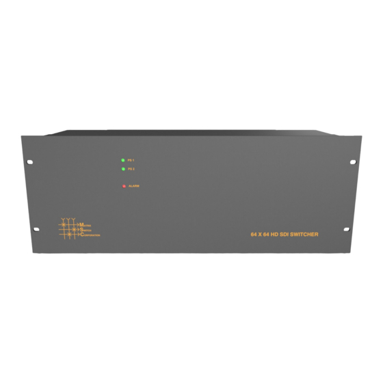
Routing matrix is initialized to Preset 0 state (defaults to source 1 connected to all destinations). • 1.4 Front Status Panel The MSC-XDM4000 has a status front panel with 3 LED indicators, described in the following table: Page 11 of 64 © 2013-2016 Matrix Switch Corporation... -
Page 12: Accessing The Web
RS-232 serial and remote control panels. 1.5 Web Page Interface All Matrix Switch Corporation router and panel devices come with a built-in web page interface. This is the recommended interface for configuration and is also a convenient way to control the matrix routing of the device. -
Page 13: Matrix Routing
Ethernet network. Larger installations or integration with existing IP LAN networks require some network planning. NOTE: Matrix Switch Corporation can assist in planning and pre-configuring devices for specific application requirements at purchase time. Just ask a sales or customer service representative. - Page 14 LAN or allow IP packet routing between networks if on separate LANs. SECURITY WARNING: Matrix Switch Corporation devices are meant for installation in trusted LAN environments. In the event that remote device configuration or control is desired over public networks or the Internet, it is strongly recommended that some form of inter-network security is utilized, such as firewalls and encrypted VLAN or secure data tunnels.
-
Page 15: Installation Example
The following diagram is of a simple installation example consisting of a 32x32 SDI Video Router, with a secondary level 32x32 Analog Audio router connected via the AFV DB-25 interface, a 32x32 Remote Button Panel, a 2RU LCD Remote Panel and a Computer system. Page 15 of 64 © 2013-2016 Matrix Switch Corporation www.matrixswitch corp.com... -
Page 16: Overview
2.1 Overview Figure 10: Routing Tab All Matrix Switch Corporation Router and Remote Panel systems include a built in web page that can be used with standards compliant Javascript enabled web browsers, including but not limited to Firefox, Chrome, Safari and recent versions of Internet Explorer. -
Page 17: Changing A Connection
No Change and Mute (the latter only if available for the given level). The No Change option indicates that the Destination for the given Level should not be changed from its current value, when the preset Page 17 of 64 © 2013-2016 Matrix Switch Corporation www.matrixswitch corp.com... -
Page 18: Loading Work Matrix From A Source Target
Editing an existing Preset – Editing a Preset is done by loading it to the Work Matrix, making the • desired changes and saving it back to the same Preset. All this is accomplished without changing the Active Routing matrix state. 2.4 Labels Tab Page 18 of 64 © 2013-2016 Matrix Switch Corporation www.matrixswitch corp.com... -
Page 19: Config Tab
Presets can also be assigned label names. Click the Save button to save changes that have been made. 2.5 Config Tab Page 19 of 64 © 2013-2016 Matrix Switch Corporation www.matrixswitch corp.com... -
Page 20: System Settings
TCP/IP network configuration. Once the save button is pressed and the system is rebooted any changes to DHCP enable, the IP Address or the Netmask shall result in having to access the web page with the Page 20 of 64 © 2013-2016 Matrix Switch Corporation www.matrixswitch corp.com... -
Page 21: Button Panel Settings
MSC-XDM4000 Product Manual new settings. If there are Matrix Switch Corporation remote control panels which access the system which has been changed, they must also be reconfigured to use the new router IP address as well. See the Network Planning section for more helpful information on planning your network. -
Page 22: Command Tab
Clicking the Clear Output button will clear all command output in the lower area. See the section Mascot Control Protocol for more information. Page 22 of 64 © 2013-2016 Matrix Switch Corporation www.matrixswitch corp.com... -
Page 23: Mascot Control Protocol
MASCOT (MAtrix Switch COrporation ProTocol) provides an ASCII text based command interface via several different transports to control and get status from Matrix Switch Corporation devices. This command protocol can be utilized for manual control or for integration with automation control systems. -
Page 24: Telnet Access
Carriage Return (ASCII 13), indicates the end of a command or chain of commands, Enter key. <BS> Backspace character (ASCII 11), can be used to backspace characters in interactive command shells. “ Used for double quoting string arguments. Page 24 of 64 © 2013-2016 Matrix Switch Corporation www.matrixswitch corp.com... -
Page 25: Command Names
E00: Error message > 00 will contain a 2 digit decimal error code. Table 6 shows possible error codes which may be returned in response to commands. Page 25 of 64 © 2013-2016 Matrix Switch Corporation www.matrixswitch corp.com... -
Page 26: Command Arguments
Square brackets indicate an optional argument and parenthesis indicate a required argument. Any optional argument specified requires that all prior optional arguments are also specified. Table 8 lists currently used command argument types. Page 26 of 64 © 2013-2016 Matrix Switch Corporation www.matrixswitch corp.com... -
Page 27: System Parameters
Set S [Parameter][Value] Set Stored value of a parameter only. Table 9: System Parameter Commands Parameter identifiers are represented as one or more alphanumeric words separated by periods, representing a Page 27 of 64 © 2013-2016 Matrix Switch Corporation www.matrixswitch corp.com... -
Page 28: System Parameter Table
AS System name identifier. 3.8 Core Commands This section outlines commands considered to be core MASCOT protocol commands and consists of matrix routing, I/O label, preset, and other primary system commands. Page 28 of 64 © 2013-2016 Matrix Switch Corporation www.matrixswitch corp.com... -
Page 29: Configuration Commands
External panel interface enable (if available). PanelOfs [Dest][Src][Lvl][Lvl] Button panel destination/source offsets and levels to control. PanelRate [Number] Remote panel refresh rate. SerBaud [Number] Query or assign serial baud rate. SysName [String] System name. Page 29 of 64 © 2013-2016 Matrix Switch Corporation www.matrixswitch corp.com... -
Page 30: Miscellaneous Commands
When querying names, labels are surrounded by double quotes and each level is separated by commas ',' (multi- level systems only) and each destination is separated by newlines. Secondary levels use empty strings to Page 30 of 64 © 2013-2016 Matrix Switch Corporation www.matrixswitch corp.com... -
Page 31: Dhcp Command
IP assignment by MAC address or if there is a way to determine what IPs the Matrix Switch Corporation systems get assigned. Otherwise it may become difficult to determine what IP address to use when accessing the Web Page or other control interfaces. In the event that the IP address or... -
Page 32: Firmware Command
FrameIP IP Set IP address of remote Router system to control (use 0.0.0.0 on Router systems to disable remote control). Example to query and assign the remote Router IP Page 32 of 64 © 2013-2016 Matrix Switch Corporation www.matrixswitch corp.com... -
Page 33: Gateway Command
Display the Active value of a single parameter or a subset of parameters under a given parameter node. Examples of querying all parameters, “mtx” parameters, and “net.ip” parameter. >Get ctl.mascot.ver=2.3 ctl.serial.baud=115200 ctl.serial.log=0 ctl.serial.proto=mascot ctl.serial2.baud=115200 ctl.serial2.log=0 ctl.serial2.proto=mascot mtx.serial=1 mtx.sync=0 net.dhcp=0 net.gateway=192.168.2.1 net.ip=192.168.2.60 net.mac=00:50:C2:8B:DF:FE Page 33 of 64 © 2013-2016 Matrix Switch Corporation www.matrixswitch corp.com... -
Page 34: Gets Command
Unknown IP Address section for this device. Command Description Query IP address of the system. Ip IP Set IP address of the system. Example querying and assigning the IP address Page 34 of 64 © 2013-2016 Matrix Switch Corporation www.matrixswitch corp.com... -
Page 35: Lockstatus Command
Display destination matrix map. Only destinations are shown which have been remapped. One destination number per line is shown separated by a colon ‘:’ and the destinations which are substituted for each level separated by commas. Page 35 of 64 © 2013-2016 Matrix Switch Corporation www.matrixswitch corp.com... -
Page 36: Mapsrc Command
Assign a source mapping on all levels for Src1 to physical Src2. MapSrc Src1 Src2 Level Assign a source mapping on a single level for Src1 to physical Src2. Examples >MapSrc 1:4,4 2:3,2 >MapSrc 1 1:4,4 > Page 36 of 64 © 2013-2016 Matrix Switch Corporation www.matrixswitch corp.com... -
Page 37: Mascotver Command
3 integer numbers specifying the destination count, source count and flags of the level. The flags value is the sum of one or more values from the Flags table below. Flags Name Value Description Page 37 of 64 © 2013-2016 Matrix Switch Corporation www.matrixswitch corp.com... - Page 38 Level type: VIDEO, AUDIO, HD, VGA, 3G, ANALOG or AES. Used for general video, general audio, HD video, VGA video, 3G HD video, analog audio or AES digital audio respectively. DEST_COUNT Count of destinations for the level. Page 38 of 64 © 2013-2016 Matrix Switch Corporation www.matrixswitch corp.com...
-
Page 39: Mtxgroup Command
I/O, which changes the size of the router matrix accordingly (matrix size divided by group count), and matrix routing changes update the grouped I/Os simultaneously. Group counts are Page 39 of 64 © 2013-2016 Matrix Switch Corporation www.matrixswitch corp.com... -
Page 40: Netmask Command
Description NetMask Query network mask value. NetMask NETMASK Set network mask value. Example querying and assigning netmask >NetMask 255.255.255.0 >NetMask 255.255.255.192 > 3.10.20 P Command Routers and MSC-GCP2U32 only Page 40 of 64 © 2013-2016 Matrix Switch Corporation www.matrixswitch corp.com... -
Page 41: Padd Command
This setting is stored and recalled on power up. Command Description PairIO Query current value of I/O pairing configuration. PairIO 0 | 1 Enable or disable I/O pairing (0: disable, 1: enable) Page 41 of 64 © 2013-2016 Matrix Switch Corporation www.matrixswitch corp.com... -
Page 42: Panelcmd Command
1 and 2 have P0 and P1 commands assigned respectively, which recalls preset 0 and preset 1, and GPIO pin 1 (GPIO pins start at 65) will recall preset 0. The second command queries the panel command for button Page 42 of 64 © 2013-2016 Matrix Switch Corporation www.matrixswitch corp.com... -
Page 43: Panelcmden Command
GPIO Auxiliary Interface for details. NOTE: Panel commands and conditions must be enabled with the PanelCmdEn Command or by setting the pnl.cmdEn S ystem P arameter to activate them. Command Description Page 43 of 64 © 2013-2016 Matrix Switch Corporation www.matrixswitch corp.com... -
Page 44: Paneldis Command
3.10.27 PanelExtEn Command Carina series only - Protocol Version: 2.4 Query or assign external button interface panel enable setting (if applicable – not all router devices have an Page 44 of 64 © 2013-2016 Matrix Switch Corporation www.matrixswitch corp.com... -
Page 45: Panelrate Command
Clear a preset. For Preset 0 this sets all Destinations to Source 0. Other Presets are assigned “No Change” to all Destinations. This command stores preset information which is available through system power cycles. Command Description PClr PRESET Clear a preset. Page 45 of 64 © 2013-2016 Matrix Switch Corporation www.matrixswitch corp.com... -
Page 46: Protoser Command
PsetNames PRESET, LABEL Assign a preset label. When querying names, labels are surrounded by double quotes and separated by newlines. Examples >PsetNames “Startup” “Preset1” “Preset2” “Preset3” “Preset4” “Preset5” “Preset6” “Preset7” “Preset8” Page 46 of 64 © 2013-2016 Matrix Switch Corporation www.matrixswitch corp.com... -
Page 47: Psub Command
'-' indicates “No Change”, which causes no changes to the given Destination/Level. • 0 indicates “Mute” • Command Description PView Display all presets. PView PRESET Display a single PRESET. Example on a 16x4 system with 2 levels >PView 1 Page 47 of 64 © 2013-2016 Matrix Switch Corporation www.matrixswitch corp.com... -
Page 48: Reboot Command
This value is stored and recalled on power up. Command Description RemoteSync Query current value of remote router syncing. RemoteSync 0 | 1 Enable or disable remote router syncing (1 or 0 respectively). Page 48 of 64 © 2013-2016 Matrix Switch Corporation www.matrixswitch corp.com... -
Page 49: S Command
Query or assign the RS-232 serial port baud rate. The default value is 115200. This value is stored and recalled on power up. Command Description SerBaud Query the current serial port baud rate. SerBaud BAUD Set the serial port baud rate. Examples >SerBaud 115200 >SerBaud 9600 > Page 49 of 64 © 2013-2016 Matrix Switch Corporation www.matrixswitch corp.com... -
Page 50: Set Command
>Set net.ip 192.168.2.60 > 3.10.40 SetA Command Protocol version 3.0 The SetA command is used for setting system parameter Active values only. Values set with this command will Page 50 of 64 © 2013-2016 Matrix Switch Corporation www.matrixswitch corp.com... -
Page 51: Sets Command
Secondary levels use empty strings to indicate that the label of the first level should be used. Examples >SrcNames “Src1”,”AudSrc1” “Src2”,”” “Src3”,”” “Src4”,”” >SrcNames 1 Page 51 of 64 © 2013-2016 Matrix Switch Corporation www.matrixswitch corp.com... -
Page 52: Sysname Command
NOTE: This command was not added until version 2.3 of the Mascot protocol. On previous versions, this command is available on the MSC-GCP2U32 LCD panel but not other Matrix Switch Corporation systems. When determining the system type, if executing the command returns an Invalid Command error, the system series can be assumed to be Carina. -
Page 53: Vars Command
Firmware=1.5.1 Gateway=192.168.2.1 IP=192.168.2.80 Mac=00:00:00:00:00:00 MascotVer=2 MtxProfiles=JSON Netmask=255.255.255.0 Profile=1 SerBaud=115200 SerProto=Mascot SysName=MSC-Panel SysType=2 > The example above shows a typical output of the Vars command for an MSC-GCP2U32 LCD panel. Page 53 of 64 © 2013-2016 Matrix Switch Corporation www.matrixswitch corp.com... -
Page 54: W Command
The value 0 can be used for DEST to switch all destinations to a given source. A level may also be specified to isolate switching a single level of all destinations. (Protocol Version 2.2) Page 54 of 64 © 2013-2016 Matrix Switch Corporation www.matrixswitch corp.com... - Page 55 > The above would connect source 4 to destination 1, source 3 to destination 2, source 2 to destination 3 and source 1 to destination 4 for all levels. Page 55 of 64 © 2013-2016 Matrix Switch Corporation www.matrixswitch corp.com...
-
Page 56: Software Updates
4.1 Software Update on Pyxis Series Devices Once a valid software update image is obtained from Matrix Switch Corporation for the applicable hardware series, the following procedure can be used to perform a software update. -
Page 57: Tftp Software
5. Make sure to replace 192.168.2.59 with the device's IP address if the update procedure being used utilizes the device’s assigned IP and replace MSC-Pyxis-Firmware-x.x.x.img with the correct version number of the file. Page 57 of 64 © 2013-2016 Matrix Switch Corporation www.matrixswitch corp.com... -
Page 58: Mac Os X
2. Open a Terminal command line application (CTRL-ALT-T will do this on many desktop environments). 3. Use 'cd' commands to change to the directory where the firmware file is located, for example (if the Page 58 of 64 © 2013-2016 Matrix Switch Corporation www.matrixswitch corp.com... - Page 59 8. The TFTP program will indicate if the transfer was successful or not. 9. If the transfer failed (timed out, etc), retry the put command or quit the application (type 'quit' and ENTER) and start over from step 4. Page 59 of 64 © 2013-2016 Matrix Switch Corporation www.matrixswitch corp.com...
-
Page 60: Troubleshooting
If the device is rebooting unexpectedly (detectable on routers when the routing state gets reset to preset 0), make sure the correct power supply is being used with the device (12 Volt 10 Amp). Page 60 of 64 © 2013-2016 Matrix Switch Corporation www.matrixswitch corp.com... -
Page 61: Reference
An RS-232 serial port is provided for system control. This interface uses serial signals with 8 data bits, No Parity, and 1 Stop Bit (8N1). The standard DE-9 pin configuration is used for a DCE device for the RX, TX and Page 61 of 64 © 2013-2016 Matrix Switch Corporation www.matrixswitch corp.com... -
Page 62: Gpio Auxiliary Interface
Pin # Name Pin # Name Pin # Name GP10 GP19 GP11 GP20 GP12 GP21 GP13 GP22 GP14 GP23 GP15 GP24 GP16 Ground GP17 GP18 Page 62 of 64 © 2013-2016 Matrix Switch Corporation www.matrixswitch corp.com... -
Page 63: Glossary
Network router, which is referred to as a Network Switch in this manual). Simple Panel – A Matrix Switch Corporation Remote Panel which has buttons only. • Smart Panel – A Matrix Switch Corporation Remote Panel which comes equipped with an LCD screen • interface. -
Page 64: Matrix Switch Corporation Warranty
MSC-XDM4000 Product Manual 7 Matrix Switch Corporation Warranty MSC provides the following limited warranty with its products: 1. MSC warrants that the equipment it manufactures is free from defects in material and workmanship. 2. This warranty begins on the day the product is shipped from MSC and shall be in effect for two years.
Need help?
Do you have a question about the MSC-XDM4000 and is the answer not in the manual?
Questions and answers