
Related Manuals for Dressler CESAR 1312

Summary of Contents for Dressler CESAR 1312
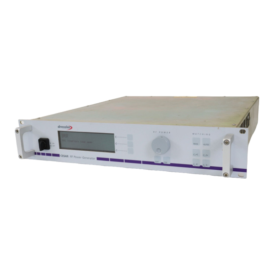
- Page 1 U s e r M a n u a l CESAR™ Generator Model 1312 s e r v i c e @ d r e s s l e r . c o m...
- Page 3 User Manual CESAR™ Generator Model 1312 CESAR 1312 (E)
-
Page 4: Disclaimer And Limitation Of Liability
Technik GmbH makes no warranty of any kind whatsoever, either expressed ® or implied, with respect to the information contained herein. Dressler Technik GmbH shall not be liable in damages, of whatever kind, as a result of the reliance on or use of the information contained herein. - Page 5 Please send any comments on the content, organization, or format of this user manual to: • tech.writing@aei.com To order a manual, please contact the Dressler Customer Service Department: • service@dressler.com CESAR 1312 (E)
- Page 6 ® Dressler HF-Technik GmbH CESAR 1312 (E)
-
Page 7: Table Of Contents
User Port—25-Pin User Port ........4-10 CESAR 1312 (E) - Page 8 Connecting AC Input (Mains) Power ....... 5-8 Connecting and Setting Ethernet (Modbus/TCP) Communication ..5-9 Table of Contents CESAR 1312 (E)
- Page 9 Troubleshooting Guide ......... . 6-2 CESAR 1312 (E)
- Page 10 Warranty Statement ......... . . 6-17 viii Table of Contents CESAR 1312 (E)
- Page 11 Fig 4-40 AE Bus communications transaction ......4-48 CESAR 1312 (E)
- Page 12 Fig 5-6 Front panel program menu tree (continued) ......5-30 List of Figures CESAR 1312 (E)
- Page 13 Table 1-1 CESAR 1312 (E) options ........
- Page 14 ® Dressler HF-Technik GmbH List of Tables CESAR 1312 (E)
-
Page 15: Chapter 1. Safety And Product Compliance Guidelines
Safety and Product Compliance Guidelines IMPORTANT SAFETY INFORMATION ® To ensure safe installation and operation of the Dressler HF-Technik GmbH CESAR generator, read and understand this manual before attempting to install and operate this unit. At a minimum, read and follow the safety instructions and practices documented under “Safety Guidelines”... -
Page 16: Understanding Model 1312 Options
“Communication Interfaces” on page 4-1. Note: To determine which option you have, find the serial tag affixed to the unit; the part number is on the serial tag. Table 1-1. CESAR 1312 (E) options Model Part User Port Options Host Port Options... -
Page 17: Danger, Warning, And Caution Boxes
Danger, Warning, and Caution Boxes This symbol represents important notes concerning potential harm to people, ® this unit, or associated equipment. Dressler HF-Technik GmbH includes this symbol in Danger, Warning, and Caution boxes to identify specific levels of hazard seriousness. -
Page 18: Interpreting Product Labels
• Use proper electrostatic discharge (ESD) precautions. • Always be careful around this equipment. Interpreting Product Labels The following labels may appear on the unit: Capacitor discharge warning CE label Hazardous voltage No user-serviceable parts inside unit Safety and Product Compliance Guidelines CESAR 1312 (E) -
Page 19: Product Compliance
Product Certification Certain options of this product are certified by: • CE marking, self addressed by Dressler Compliance Engineering • EMC measurements, verified by Competent Body Product Services For more information, refer to the letter of conformance (US) or declaration of conformity (EU) accompanying the product. -
Page 20: Safety Directives And Standards
4 A steady force of 445 N, applied through a steel hemisphere 12.7 mm in diameter 4 An impact of 7 J applied by dropping or swinging a 0.53 kg, 50 mm diameter steel sphere Safety and Product Compliance Guidelines CESAR 1312 (E) -
Page 21: Interlocks And Limits
RF power. Even if you do not connect this CESAR generator into a larger system interlock loop, you must make the proper interlock loop connections for the unit to enable RF power. CESAR 1312 (E) Safety and Product Compliance Guidelines... -
Page 22: Table 1-4 Cesar Generator Limits
Table 4-2 on page 4-13 or pin 4 Table 4-4 on page 4-31, depending on which option you have. To determine which option you have, see “Understanding Model 1312 Options” on page 1-2. Safety and Product Compliance Guidelines CESAR 1312 (E) - Page 23 The target lifetime warning occurs when the target lifetime reaches the user-set limit. This warning does not affect the operation of the unit. For more information, see W50 in Table 6-2 on page 6-11. CESAR 1312 (E) Safety and Product Compliance Guidelines...
- Page 24 ® Dressler HF-Technik GmbH 1-10 Safety and Product Compliance Guidelines CESAR 1312 (E)
-
Page 25: Chapter 2. Product Overview And Theory
The CESAR generator operates from a 230 VAC, 50/60 Hz power source. The CESAR generator is air-cooled and has all power and interface-port connections at the rear of the generator (see “Rear View Drawings” on page 4-2). CESAR 1312 (E) Product Overview and Theory... -
Page 26: Theory Of Operation
This module is the main processor and data acquisition section. It also provides Host communications through a Host port. (6) Sensor This module detects RF samples and sends them to the Electronics microprocessor. Product Overview and Theory CESAR 1312 (E) -
Page 27: Chapter 3. Specifications
The following sections describe the dimensions and physical specifications of the CESAR generator. All generator specifications are also available online; please visit http://www.dressler.com/products/generators. • “Unit Dimensions” on page 3-2 • “Physical Specifications Table” on page 3-3 CESAR 1312 (E) Specifications... -
Page 28: Unit Dimensions
® Dressler HF-Technik GmbH Unit Dimensions The following illustration shows the dimensions of the CESAR generator. Figure 3-1. CESAR Generator unit dimensions Specifications CESAR 1312 (E) -
Page 29: Physical Specifications Table
“User Port—15-Pin User Port” on page 4-28). To determine which analog interface you have, see “Understanding Model 1312 Options” on page 1-2. For more information on the analog interfaces, see “CESAR Generator User Port Options” on page 4-10. CESAR 1312 (E) Specifications... -
Page 30: Electrical Specifications
Input power specifications 230 VAC (187 VAC to 253 VAC), 1 φ with ground Line voltage (PE) Line Frequency 50/60 Hz Line current 8 A nominal line, full power Input power 1780 VA Power factor 97% to 99% Specifications CESAR 1312 (E) - Page 31 RF Pulse frequency 1 Hz to 30 kHz RF Pulse Duty Cycle 0% to 99% CEX Specifications TTL; 0 to +10 dBm; 50 Ω CEX input signal Ω CEX output signal ; +3 to +10 dBm; 50 CESAR 1312 (E) Specifications...
-
Page 32: Cooling Specifications
Noncondensing Note Maximum relative humidity when the unit temperature slowly increases, or when the unit temperature directly increases from -25°C to +30°C Note Maximum absolute humidity when the unit temperature directly decreases from +70°C to +15°C Specifications CESAR 1312 (E) -
Page 33: Table 3-5 Environmental Specifications
Maximum relative humidity when the unit temperature slowly increases, or when the unit temperature directly increases from -25°C to +30°C Note Maximum absolute humidity when the unit temperature directly decreases from +70°C to +15°C Table 3-5. Environmental specifications Description Specification Overvoltage Category II Pollution Degree 2 CESAR 1312 (E) Specifications... - Page 34 ® Dressler HF-Technik GmbH Specifications CESAR 1312 (E)
-
Page 35: Chapter 4. Communication Interfaces
“Rear view with 25-pin User port and Ethernet port (pn 61300060)”, see Figure 4-5 on page 4-6. • For an illustration of the “Rear view with 25-pin User port and PROFIBUS port (pn 61300061)”, see Figure 4-6 on page 4-7. CESAR 1312 (E) Communication Interfaces... -
Page 36: Rear View Drawings
® Dressler HF-Technik GmbH REAR VIEW DRAWINGS Figure 4-1. Rear view with 15-pin User port and RS-232 port (pn 61300056) Communication Interfaces CESAR 1312 (E) - Page 37 CESAR™ 1312 Generator Figure 4-2. Rear view with 15-pin User port and Ethernet port (pn 61300057) CESAR 1312 (E) Communication Interfaces...
- Page 38 ® Dressler HF-Technik GmbH Figure 4-3. Rear view with 15-pin User port and PROFIBUS port (pn 61300058) Communication Interfaces CESAR 1312 (E)
- Page 39 CESAR™ 1312 Generator Figure 4-4. Rear view with 25-pin User port and RS-232 port (pn 61300059) CESAR 1312 (E) Communication Interfaces...
- Page 40 ® Dressler HF-Technik GmbH Figure 4-5. Rear view with 25-pin User port and Ethernet port (pn 61300060) Communication Interfaces CESAR 1312 (E)
- Page 41 CESAR™ 1312 Generator Figure 4-6. Rear view with 25-pin User port and PROFIBUS port (pn 61300061) CESAR 1312 (E) Communication Interfaces...
-
Page 42: Diagnostic Interface
MATCHING INTERFACE Each CESAR generator has a Matching Interface that allows full communication between the CESAR generator and a Dressler Variomatch matching network (or other electrically compatible matching network). The matching interface is a 15-pin, subminiature-D, female connector. - Page 43 DC self bias voltage. The VOLTAGE scaling is adjustable. For example, in the default configuration of the Dressler Variomatch, 4000 V bias voltage is equal to 10 V test voltage and is displayed on the front panel as 4000.
-
Page 44: Cesar Generator User Port Options
This section describes the 25-pin User Port port. For information on the 15- pin User Port, see “User Port—15-Pin User Port” on page 4-28. Note: To determine which option you have, see “Understanding Model 1312 Options” on page 1-2. 4-10 Communication Interfaces CESAR 1312 (E) -
Page 45: User Port Connector
Connect the CESAR generator’s 25-pin User Port to the system controller with a shielded, 25-wire I/O cable. Shielded twisted-pair wiring is recommended but not mandatory. Minimize signal losses by keeping the cable as short as possible. The maximum recommended cable length between the CESAR 1312 (E) Communication Interfaces 4-11... -
Page 46: Activating The 25-Pin User Port
2. Press Next until you see Device Configuration on the display. 3. Press Change. 4. Press OK until you see Control by on the right-hand side of the screen. 5. Press User Port. 6. Press Execute. 4-12 Communication Interfaces CESAR 1312 (E) -
Page 47: 25-Pin User Port Pin Descriptions
(see “Analog Outputs” on page 4-21). Default setting: 0 V to 10 V = 0 W to 1.2 kW For a wiring diagram, see Figure 4-9 on page 4-22. Pin 15 must be grounded. CESAR 1312 (E) Communication Interfaces 4-13... - Page 48 5-15. To change control settings, see pin 8.) Default setting: 0 V to 10 V = 0 W to 1.2 kW For a wiring diagram, see Figure 4-10 on page 4-22. Pin 16 must be grounded. 4-14 Communication Interfaces CESAR 1312 (E)
-
Page 49: Table 4-2 25-Pin User Port Pin Descriptions
(see “Satisfying Minimal 25- Pin User Port Requirements” on page 4-11) and the set point must be within the output power range (see “Electrical specifications” on page 3-4). Pin 17 must be grounded. CESAR 1312 (E) Communication Interfaces 4-15... - Page 50 1.5 V or less or an open connection. See pin 8 for switching between forward and load power regulation. For a wiring diagram, see Figure 4-13 on page 4-24. 4-16 Communication Interfaces CESAR 1312 (E)
- Page 51 DC bias voltage is used for DC bias regulation (see pin 6), the scaling must be the same as for the set point (see pin 5). Dressler Variomatch matching networks provide a DC bias voltage monitor signal for regulation through the Matching Interface.
- Page 52 +4 V to +30 V (referenced to ground) to pin For a wiring diagram, see Figure 4-16 on page 4-25. Return for pin 24 See pin 24. Reserved 4-18 Communication Interfaces CESAR 1312 (E)
- Page 53 (opto-coupler output) impedance is created between this pin and return pin 9 (8 mA maximum). For a wiring diagram, see Figure 4-19 on page 4-27. Return for pin 10 See pin 10. CESAR 1312 (E) Communication Interfaces 4-19...
-
Page 54: 25-Pin User Port Electrical Characteristics
0 V to 10 V. These signals are scalable from 0 V to 2V up to 0 V to 10 V in increments of 0.5 V. You can set the scaling through the RS-232 port 4-20 Communication Interfaces CESAR 1312 (E) - Page 55 The interlock signal (pins 10 and 23) enables the RF power generation. Pin 10 is tied to the generator’s +15 V supply. Connecting pin 10 to pin 23 closes the loop, enabling RF power. CESAR 1312 (E) Communication Interfaces 4-21...
-
Page 56: 25-Pin User Port Wiring Diagrams
User Port. For detailed pin descriptions, see “25-Pin User Port Pin Descriptions” on page 4-13. Figure 4-9. REFLECTED POWER MONITOR signal wiring (pins 2 and 15) Figure 4-10. RF FORWARD/LOAD POWER MONITOR signal wiring (pins 3 and 16) 4-22 Communication Interfaces CESAR 1312 (E) - Page 57 CESAR™ 1312 Generator Figure 4-11. RF POWER ON signal wiring (pins 4 and 17) Figure 4-12. SET POINT signal wiring (pins 5 and 18) CESAR 1312 (E) Communication Interfaces 4-23...
- Page 58 ® Dressler HF-Technik GmbH Figure 4-13. RF FORWARD POWER/DC BIAS REGULATION wiring (pins 6 and 19) Figure 4-14. DC BIAS MONITOR signal wiring (pins 7 and 20) 4-24 Communication Interfaces CESAR 1312 (E)
- Page 59 CESAR™ 1312 Generator Figure 4-15. RF FORWARD/LOAD REGULATION signal wiring (pins 8 and Figure 4-16. INTERLOCK LOOP signal wiring (pins 10 and 23) CESAR 1312 (E) Communication Interfaces 4-25...
- Page 60 ® Dressler HF-Technik GmbH Figure 4-17. +15 VOLT DC signal wiring (pins 13 and 21) Figure 4-18. SET POINT STATUS signal wiring (pins 14 and 1) 4-26 Communication Interfaces CESAR 1312 (E)
- Page 61 CESAR™ 1312 Generator Figure 4-19. OVERTEMPERATURE signal wiring (pins 22 and 9) Figure 4-20. INTERLOCK SATISFIED signal wiring (pins 24 and 11) CESAR 1312 (E) Communication Interfaces 4-27...
-
Page 62: User Port-15-Pin User Port
The 15-pin User Port option offers basic control and monitoring capability. The 15-pin User Port has a shielded, male, subminiature-D connector (see Figure 4-22) that connects the generator with an external remote control unit. Figure 4-22. 15-pin User Port connector 4-28 Communication Interfaces CESAR 1312 (E) -
Page 63: Satisfying The Interlock
You can use this jumper plug to satisfy the interlock and enable operation in situations where you do not intend to connect the remaining pins on this port. Using the interlock jumper plug disables the interlock function. CESAR 1312 (E) Communication Interfaces 4-29... -
Page 64: Table 4-3 Interlock Interface Pin Descriptions
This pin must be used as return for the external interlock voltage, because the interlock input (pin 1) is floating and has no reference to ground. Connect to the shield of the external interlock cable. 4-30 Communication Interfaces CESAR 1312 (E) -
Page 65: 15-Pin User Port Cabling Requirements
For a wiring diagram, see Figure 4- 25 on page 4-36. READY Digital This signal Indicates that the STATUS output generator is ready for operation. For a wiring diagram, see Figure 4- 26 on page 4-37. CESAR 1312 (E) Communication Interfaces 4-31... - Page 66 Table 3-2 on page 3-4.) For information on resolving this error, see WW11, W12, and W13 in Table 6-2 on page 6-11. For a wiring diagram, see Figure 4- 28 on page 4-38. 4-32 Communication Interfaces CESAR 1312 (E)
- Page 67 (see “To Change the Default Device Configuration Settings Using the CESAR Generator Front Panel:” on page 5-41). For a wiring diagram, see Figure 4- 31 on page 4-39. CESAR 1312 (E) Communication Interfaces 4-33...
- Page 68 0 V to 10 V, but you can change this range (see “Analog Outputs” on page 4-21) 0 V to 10 V = 0 W to “XXX kW” For a wiring diagram, see Figure 4- 35 on page 4-41. 4-34 Communication Interfaces CESAR 1312 (E)
-
Page 69: Table 4-5 Setting Regulation Mode With 15-Pin User Port Pins 1 And 2
Mode A Mode B Setting (Pin 1) (Pin 2) Local No remote control function High Remote RF forward power (P forward High Remote External power (DC Bias High High Remote Load power (P real CESAR 1312 (E) Communication Interfaces 4-35... -
Page 70: 15-Pin User Port Wiring Diagrams
The following schematics illustrate how to properly connect the CESAR generator 15-pin User Port. For detailed pin descriptions, see Table 4-4. Figure 4-24. OPERATING MODE A wiring diagram (pins 1 and 8) Figure 4-25. OPEATING MODE B wiring diagram (pins 2 and 8) 4-36 Communication Interfaces CESAR 1312 (E) - Page 71 CESAR™ 1312 Generator Figure 4-26. READY STATUS wiring diagram (pins 3 and 8) Figure 4-27. ERROR wiring diagram (pins 4 and 8) CESAR 1312 (E) Communication Interfaces 4-37...
- Page 72 ® Dressler HF-Technik GmbH Figure 4-28. MAXIMUM POWER LEVEL REACHED wiring diagram (pins 5 and 8) Figure 4-29. RF ON wiring diagram (pins 6 and 8) 4-38 Communication Interfaces CESAR 1312 (E)
- Page 73 CESAR™ 1312 Generator Figure 4-30. INTERFACE VOLTAGE wiring diagram (pins 7 and 8) Figure 4-31. BLANKING/PULSING MODE wiring diagram (pins 9 and 8) CESAR 1312 (E) Communication Interfaces 4-39...
- Page 74 ® Dressler HF-Technik GmbH Figure 4-32. RF POWER ON wiring diagram (pins 10 and 8) Figure 4-33. DC BIAS SET POINT wiring diagram (pins 11 and 8) 4-40 Communication Interfaces CESAR 1312 (E)
- Page 75 CESAR™ 1312 Generator Figure 4-34. RF POWER SET POINT wiring diagram (pins 12 and 8) Figure 4-35. TEST VOLTAGE FOWARD POWER wiring diagram (pins 13 and 8) CESAR 1312 (E) Communication Interfaces 4-41...
-
Page 76: Cesar Generator Host Port Options
The following sections provide information for each of the host port options available with the CESAR generator. • “Host Port—RS-232 With AE Bus” on page 4-43 4-42 Communication Interfaces CESAR 1312 (E) -
Page 77: Host Port-Rs-232 With Ae Bus
The RS-232 AE Bus host port interface uses an RS-232 signal format and AE Bus communication protocol. Refer to “AE Bus Protocol” for details on the communications protocol. For a complete list of available functions, see “Host Port Commands” on page 4-61. CESAR 1312 (E) Communication Interfaces 4-43... -
Page 78: Rs-232 Connector And Pin Descriptions
The communications capability of the serial RS-232 host port is limited to the following parameters: • RS-232 protocol transmission standard • Five baud rates selected on the front panel (see “Changing the Device Configuration Settings” on page 5-40): 4 9600 4 19200 4 38400 4-44 Communication Interfaces CESAR 1312 (E) -
Page 79: Ae Bus Protocol
Five types of information (fields) make up communications message packets (see Figure 4-39): • Header (address and the length of Data field) • Command Number (commands are listed in Table 4-16 on page 4-63) • Optional Length byte • Data • Checksum CESAR 1312 (E) Communication Interfaces 4-45... - Page 80 This one-byte field contains an 8-bit value from 0 to 255 (00h to ffh) representing the command number. If the message packet originates with the host computer, this value specifies the purpose of the message packet. If the 4-46 Communication Interfaces CESAR 1312 (E)
- Page 81 If the result is zero, the unit has received the packet intact. The unit will act on the message only if the address is valid and the checksum is validated as having no parity errors. CESAR 1312 (E) Communication Interfaces 4-47...
-
Page 82: Creating An Ideal Communications Transaction
CESAR generator verifies that the message is intended for it and not for another unit on the network. At this time, the CESAR generator also analyzes the checksum to verify that the message was received correctly. 4-48 Communication Interfaces CESAR 1312 (E) - Page 83 The CESAR generator continues to retransmit in response to NAK transmissions until the host computer stops the cycle. If the CESAR generator receives no response, it assumes an ACK and returns to the waiting state. CESAR 1312 (E) Communication Interfaces 4-49...
-
Page 84: Host Port-Profibus
This section describes the PROFIBUS status LEDs, pins, and communication protocol. It also includes a list and description of the PROFIBUS commands. Note: Dressler’s PROFIBUS protocol does not support the following functions: address changing, freeze/unfreeze modes, or sync modes. Figure 4-42. PROFIBUS port connector... -
Page 85: Profibus Connector And Pin Descriptions
PROFIBUS PROTOCOL PROFIBUS (Process Field Bus) is an interface that lets you communicate with the CESAR generator from a host (master). Dressler manufactures a certified PROFIBUS, which means the interface is tested and certified to work with PROFIBUS masters described in the DIN 19245 PROFIBUS Standard DP, part III. -
Page 86: Table 4-8 Profibus Status Leds
PROFIBUS cable (not included). PROFIBUS Baud Rate The auto-baud feature of Dressler’s certified PROFIBUS interface adjusts automatically to the rate of the PROFIBUS master system. Baud rates are available in discrete steps from 9600 bits (9.6 kbits) to 12 Mbits. The auto-... - Page 87 Send the master reset command, Command 119, when the CESAR generator supply has experienced a non-recoverable (“explicit clear”) fault (that is, a configuration fault or a PROFIBUS error fault). Dressler recommends sending this command upon the startup of PROFIBUS communications so that any existing fault indications will be cleared.
-
Page 88: Table 4-9 Configuration Of Download Bytes (Outbytes)
PROFIBUS Command Structure The PROFIBUS is command-based. Dressler defines a download packet (“outbytes”) and an upload packet (“inbytes”) as described in the following sections of this chapter. Command lists follow. -
Page 89: Table 4-10 Configuration Of Upload Packet (Inbytes)
Delivered power low Delivered power high Forward power low Forward power high Reflected power low Reflected power high Data byte (LSB) Data byte Data byte Data byte Data byte (MSB) Data field definition CESAR 1312 (E) Communication Interfaces 4-55... -
Page 90: Host Port-Ethernet (Modbus/Tcp)
“Host Port—RS-232 With AE Bus” on page 4-43. For information on the PROFIBUS host port, see “Host Port—PROFIBUS” on page 4-50. Note: To determine which option you have, see “Understanding Model 1312 Options” on page 1-2. 4-56 Communication Interfaces CESAR 1312 (E) -
Page 91: Understanding Modbus/Tcp Commands And Register Types
For more information and specific register information, see page 4-58. The CESAR generator may reply to Modbus/TCP commands with the following exception codes: • 01 (illegal function) • 02 (illegal register reference) • 03 (illegal data value) CESAR 1312 (E) Communication Interfaces 4-57... -
Page 92: Table 4-12 Packet Format For Fc23 Send
Numbers 0 and 1 Transaction ID Not used (value is copied into reply) 2 and 3 Protocol ID 4 and 5 Number of Count of bytes in packet, starting with bytes following byte 6 4-58 Communication Interfaces CESAR 1312 (E) - Page 93 Table 4-16 on page 4-63. Note: Modbus word swapping does not affect the order of these bytes. These bytes should be ordered as necessary for the AE Bus command (least significant bytes first). CESAR 1312 (E) Communication Interfaces 4-59...
-
Page 94: Table 4-13 Packet Format For Fc23 Response
“Host Port Commands” on page 4-61. Note: Modbus word swapping does not affect the order of these bytes. These bytes are ordered as necessary for the AE Bus command (least significant bytes first). 4-60 Communication Interfaces CESAR 1312 (E) -
Page 95: Host Port Commands
4-63). The following sections describe the command status response (CSR) codes returned by the CESAR generator in response to a host port command, as well as the host port commands for the CESAR generator. CESAR 1312 (E) Communication Interfaces 4-61... -
Page 96: Activating Host Port Control
For more information on CSR codes, “Host Port Command Status Response (CSR) Codes” on page 4-62. 4-62 Communication Interfaces CESAR 1312 (E) -
Page 97: Table 4-16 Host Port Commands
• 8 = External power (DC Bias) regulation Note: You cannot change regulation mode while RF power is on. For a description of regulation modes, “Setting Regulation Mode” on page 5-15. Read back with command 154. CESAR 1312 (E) Communication Interfaces 4-63... - Page 98 Send two data bytes, least significant byte first, representing the set point level in watts. • Accepts a value of 0 to nominal power (or maximum external feedback value). Read back with command 164. 4-64 Communication Interfaces CESAR 1312 (E)
- Page 99 (see next life in hundredths of kWh (for row for example, 100 = 1 kWh). Profibus version of For more information, see “Setting a command) Target Lifetime” on page 5-47. Read back with command 157. CESAR 1312 (E) Communication Interfaces 4-65...
- Page 100 Bus/ Ethernet Read back with command 157. version of command) Sets the tuner control if the CESAR generator is connected to a Dressler (CSR only) tuner control Variomatch unit through the matching interface. (For more information on this interface, see “Matching Interface”...
- Page 101 “Operating the CESAR Generator Using the Front Panel” on page 5-24) Note: If you try to change the control mode while the unit is on, the unit automatically switches off. Read back with command 155. CESAR 1312 (E) Communication Interfaces 4-67...
- Page 102 17 is used. Note: This command is not available on generators with fixed frequency. For more information, see “Controlling the Matchbox” on page 5-20. Read back with 187. 4-68 Communication Interfaces CESAR 1312 (E)
- Page 103 Send one data byte, representing the recipe desired number of recipe steps steps • Accepts a value of 0 through 2. Note: 0 disables recipe settings. For more information, see “Creating Recipes” on page 5-45. CESAR 1312 (E) Communication Interfaces 4-69...
- Page 104 • Bytes 2 and 3 specify the set point value. Note: The set point value must be within the operating range (see “Electrical specifications” on page 3-4). For more information, see “Creating Recipes” on page 5-45. Read back with command 188. 4-70 Communication Interfaces CESAR 1312 (E)
- Page 105 • 3 = External pulsing inverted • 4 = Enable internal pulsing by external pulsing input See also commands 93 and 96. For more information, see “Using the Pulsing Function” on page 5-44. Read back with command 177. CESAR 1312 (E) Communication Interfaces 4-71...
- Page 106 4 5 = RF On/Off buttons enabled Rotating knob disabled Matching buttons enabled 4 6 = RF On/Off buttons disabled Rotating knob enabled Matching buttons enabled 4 7 = RF On/Off buttons enabled Rotating knob enabled Matching buttons enabled 4-72 Communication Interfaces CESAR 1312 (E)
- Page 107 Note: If the time is set to 0, this function is disabled. For more information, see “Changing Reflected Power Settings” on page 5-48. Read back with command 152. CESAR 1312 (E) Communication Interfaces 4-73...
- Page 108 (see “Electrical Specifications” on page 3-4). See also commands 27 and 96. For more information, see “Using the Pulsing Function” on page 5-44. Read back with command 193. 4-74 Communication Interfaces CESAR 1312 (E)
- Page 109 Send two data bytes to move the load motor to its new position. • Accepts a value of 0 to 1000 For more information, see “Setting Automatic Tune Control” on page 5-22. Read back with command 175. CESAR 1312 (E) Communication Interfaces 4-75...
- Page 110 ASCII characters (for example, CESAR). bytes supply type 5 ASCII characters Reports the output capacity of the 5 data generator; returning packet contains 5 bytes supply size ASCII characters (for example, _1350). 5 ASCII characters 4-76 Communication Interfaces CESAR 1312 (E)
- Page 111 • Bytes 1 and 2 represent rise time in times tenths of a second. • Bytes 3 and 4 represent fall time in tenths of a second. Set with commands 31 and 32. CESAR 1312 (E) Communication Interfaces 4-77...
- Page 112 • 2 = Host • 4 = User Port • 6 = Local (Front Panel) Set with command 14. Reports the number of the active target. report Set with command 11. active target 4-78 Communication Interfaces CESAR 1312 (E)
- Page 113 The controller returns the target life in hundredths of kilowatt hours (for example, 100 = 1 kWh). Set with command 12. Reports User Port (analog) voltage scaling. report User Port scaling Set with command 30. CESAR 1312 (E) Communication Interfaces 4-79...
- Page 114 • 1 = Reserved • 2 = Reserved • 3 = Unassigned • 4 = Reserved • 5 = Out of set point • 6 = Reserved • 7 = Reserved (continued on next page) 4-80 Communication Interfaces CESAR 1312 (E)
- Page 115 Matching Interface connector. Returns one data byte: • 0 = Manual control • 1 = Automatic control Set with command 13. CESAR 1312 (E) Communication Interfaces 4-81...
- Page 116 Both bytes represent delivered power (LSB first). Reports a snapshot of external feedback level at that instant. report external The controller returns two data bytes feedback representing the external feedback (LSB (DC Bias) first). 4-82 Communication Interfaces CESAR 1312 (E)
- Page 117 • 4 = Enable internal pulsing by external pulsing input Set with command 27. Reports RF frequency in Hertz. report RF Note: This command is only available on frequency generators with variable frequency. Set with command 18. CESAR 1312 (E) Communication Interfaces 4-83...
- Page 118 Reports the ramp time for the selected recipe step. The controller returns two report recipe step data bytes: ramp time • Bytes 1 and 2 represent the recipe step ramp time in tenths of seconds. Set with command 21. 4-84 Communication Interfaces CESAR 1312 (E)
- Page 119 Reports the total time that the generator was producing output power. report run time The controller returns four data bytes, least significant byte first, representing the amount of time in seconds that the unit was producing output power. CESAR 1312 (E) Communication Interfaces 4-85...
- Page 120 Returns sensor data: report • Bytes 0 and 1 = Reserved sensor data • Bytes 2 and 3 = Condensation The controller returns four data bytes representing the serial number (LSB first) report unit serial number 4-86 Communication Interfaces CESAR 1312 (E)
-
Page 121: Chapter 5. Installation, Setup, And Operation
Additional space for connectors and cabling can be necessary. Also, allow adequate space for anyone who may need to access the front and rear panels. For a dimensional drawing, see “Unit Dimensions” on page 3-2. CESAR 1312 (E) Installation, Setup, and Operation... -
Page 122: Installation Requirements
• 4 mounting screws (if you are rack-mounting the unit) and an appropriate screwdriver • A matching network (if you are using the generator with a matching network). The CESAR generator is compatible with a Dressler Variomatch or a matching network with the same control functions and electronic topology. -
Page 123: Unpacking
Unpack and inspect the unit carefully, looking for obvious physical damage. If no damage is apparent, proceed with the installation. If you do see signs of ® shipping damage, contact Dressler HF-Technik GmbH and the carrier immediately (see “Customer Support” on page 6-14). -
Page 124: Grounding
Table 5-1. Output connector pin descriptions Description Center RF output Outer Ground To Connect RF Output: 1. Connect one end of a shielded coaxial cable of 50 Ω impedance to the RF Out connector. Installation, Setup, and Operation CESAR 1312 (E) -
Page 125: Connecting Communication Interfaces
“Understanding Model 1312 Options” on page 1-2. SATISFYING THE INTERLOCK WITH A 25-PIN USER PORT If you have a 25-pin User Port, see the instructions for “Satisfying Minimal 25- Pin User Port Requirements” on page 4-11. CESAR 1312 (E) Installation, Setup, and Operation... -
Page 126: Satisfying The Interlock With A 15-Pin User Port
If you want the CESAR generator to control a matching network and/or to read the DC self-bias voltage, you must connect a matching unit. The CESAR generator is compatible with a Dressler Variomatch or a matching network with the same control functions and electronic topology. For specific information on the Matching interface, including pin descriptions, see “Matching Interface”... -
Page 127: Connecting Common Exciter (Cex) Circuitry (Optional)
When a generator receives CEX input within the following specifications, it automatically frequency-locks to that signal: • Required input signal amplitude: TTL • Input and output frequency: 13.56 MHz ±0.005% • Input impedance: 50 Ω • Output signal amplitude: TTL CESAR 1312 (E) Installation, Setup, and Operation... -
Page 128: Connecting Ac Input (Mains) Power
230 VAC (187 VAC to 253 VAC), 1 φ. Note: The ON/OFF power switch does not completely disconnect the Mains. You must install an external switch to completely disconnect Mains. Installation, Setup, and Operation CESAR 1312 (E) -
Page 129: Connecting And Setting Ethernet (Modbus/Tcp) Communication
If the address is free at the moment you send the ping command, the result will be “Request timed out.” For more information on using the ping command and the Command Prompt, see the Windows Help (available under the Windows Start button). CESAR 1312 (E) Installation, Setup, and Operation... -
Page 130: First-Time Operation
• “Operating the CESAR Generator for the First Time With the User Port” on page 5-11 • “Operating the CESAR Generator for the First Time With Host Port” on page 5-13 5-10 Installation, Setup, and Operation CESAR 1312 (E) -
Page 131: Operating The Cesar Generator For The First Time With The User Port
Operate the CESAR Generator for the First Time Using the 15-pin User Port:” on page 5-12. Note: To determine which User Port option you have, see “CESAR 1312 (E) options” on page 1-2. To Operate the CESAR Generator for the First Time Using the 25-pin User Port: 1. - Page 132 If not, see “Matching Network Troubleshooting” on page 6-2. 10. Vary the chamber conditions according to your process requirements, and verify that the CESAR generator can cover the required load impedance range. 5-12 Installation, Setup, and Operation CESAR 1312 (E)
-
Page 133: Operating The Cesar Generator For The First Time With Host Port
4-42). This section describes operating procedures for all Host port options. Note: To determine which option you have, see “CESAR 1312 (E) options” on page 1-2 To Operate the CESAR Generator for the First Time Using the Host Port: 1. If the generator is not connected to a system interlock loop, verify that the User Port interlock signal is satisfied. -
Page 134: Operating The Cesar Generator For The First Time Using The Front Panel
Is the plasma lit? If not, you may have a faulty connector or too little input power (see “Troubleshooting Guide” on page 6-2). b. Is the plasma stable (that is, is the plasma producing a constant glow)? If not, see “Troubleshooting Guide” on page 6-2. 5-14 Installation, Setup, and Operation CESAR 1312 (E) -
Page 135: Normal Operation
The regulation mode setting is retained in nonvolatile memory. DETERMINING THE REGULATION MODE SETTING The following procedures explain how to determine the regulation mode using either the Host port or the front panel. CESAR 1312 (E) Installation, Setup, and Operation 5-15... -
Page 136: Setting Forward Power Regulation Mode (Pforward )
If you are using the 25-pin User Port, see pin 8, “RF forward/load power regulation” on page 4-18. If you are using the 15-pin User Port, see pin 2, “Operating Mode B” on page 4-31 Table 4-5 on page 4-35. 5-16 Installation, Setup, and Operation CESAR 1312 (E) -
Page 137: Setting Load Power Regulation Mode (Preal )
“Operating Mode B” on page 4-31 Table 4-5 on page 4-35. To Select Load Power Regulation through the Host Port: If you are using RS-232, PROFIBUS, or Ethernet to control and monitor the CESAR generator: CESAR 1312 (E) Installation, Setup, and Operation 5-17... -
Page 138: Setting External Power Regulation Mode (Dc Bias)
If you are using the 25-pin User Port, see pin 8, “RF forward/load power regulation” on page 4-18. If you are using the 15-pin User Port, see pin 2, “Operating Mode B” on page 4-31 Table 4-5 on page 4-35. 5-18 Installation, Setup, and Operation CESAR 1312 (E) - Page 139 7. Press Ok to confirm. 8. Press Exit. 9. Press Execute. The operating screen will then display DC Bias in volts, the maximum forward power in watts, and the Program and Display soft keys. CESAR 1312 (E) Installation, Setup, and Operation 5-19...
-
Page 140: Controlling The Matchbox
HF-Technik GmbH Controlling the Matchbox If the CESAR generator is attached to a Dressler Variomatch, you can control the matchbox manually or automatically. The matching network can operate as a variable tuner or as a fixed match. In manual tune control, you can set initial tuning capacitor positions;... -
Page 141: Setting Manual Tune Control
To manually change the tune positions from these initial positions, see “To Adjust the Tune and Load Capacitors Using the CESAR Generator Front Panel:” on page 5-44. CESAR 1312 (E) Installation, Setup, and Operation 5-21... -
Page 142: Setting Automatic Tune Control
Dressler HF-Technik GmbH SETTING AUTOMATIC TUNE CONTROL Dressler recommends automatic tune control for standard matchbox operation. In automatic tune control, the matchbox automatically adjusts the capacitor positions to minimize reflected power. When a matchbox is attached and automatic tuning is set, the matchbox automatically adjusts the capacitor positions to minimize reflected power. - Page 143 4 If the plasma fails to ignite, experiment to find a position where the plasma will ignite; then make small adjustments from that point to find the optimum positions. CESAR 1312 (E) Installation, Setup, and Operation 5-23...
-
Page 144: Operating The Cesar Generator Using The Front Panel
• Understanding the basic front panel control elements • Using the front panel Program menu • Setting and using Preset generator settings • Using the display settings • Controlling a Dressler Variomatch unit that connected to the generator through the matching interface 5-24 Installation, Setup, and Operation... -
Page 145: Understanding Basic Front Panel Control Elements
The RF POWER OFF and ON key turn RF power off or on. ON key • To turn off RF power, press the left OFF key. • To turn on RF power, press the right ON key. CESAR 1312 (E) Installation, Setup, and Operation 5-25... -
Page 146: Using The Front Panel Program Menu
You can manually set these functions to meet your specific process needs, and you can store up to ten presets for ten different applications. (To set presets, see “Setting and Using Preset Generator Settings for Different Applications” on page 5-42.) 5-26 Installation, Setup, and Operation CESAR 1312 (E) -
Page 147: Accessing The Program Menu
• Press Change to view the submenu for any particular function, and follow the submenu prompts. • Press Exit to exit the program menu to quit a menu or to execute or store the programmed settings. CESAR 1312 (E) Installation, Setup, and Operation 5-27... -
Page 148: Entering Values In The Program Menu
Next repeatedly until you again reach the desired function. For more specific menu information, see “Front Panel Program Menu Tree” on page 5-29 5-28 Installation, Setup, and Operation CESAR 1312 (E) -
Page 149: Front Panel Program Menu Tree
Time Frame T3 Time Frame T4 On/Off Keys RF On/Off Remote Control Override Remote Rot. Knob RF Pwr. Setpnt Remote Matching Keys Matching Remote More Figure 5-5. Front panel program menu tree CESAR 1312 (E) Installation, Setup, and Operation 5-29... -
Page 150: Regulation Mode Settings
• Forward power regulation (P forward In forward power regulation, the CESAR Generator regulates RF power with constant forward power. • Load power regulation, or delivered power regulation (P real 5-30 Installation, Setup, and Operation CESAR 1312 (E) -
Page 151: Match Settings
MATCH SETTINGS If your RF power delivery system includes a Dressler Variomatch connected to the matching interface of the CESAR generator, you can use this function to control the matching network. This function enables you to set initial tuning... - Page 152 To manually change the capacitor positions from these initial positions, see “To Adjust the Tune and Load Capacitors Using the CESAR Generator Front Panel:” on page 5-44. 5-32 Installation, Setup, and Operation CESAR 1312 (E)
-
Page 153: Setting The Pulse Function
The operating screen will change to display the pulsing status. To Turn Off Pulsing Using the CESAR Generator Front Panel: 1. Press the Program soft key. 2. Press Next until you see Pulse Settings on the display. CESAR 1312 (E) Installation, Setup, and Operation 5-33... -
Page 154: Recipe Settings
2. Press Next until you see Recipe Settings on the display. 3. Press Change. 4. Press Power Ramping. a. Select the number of time frames (1 to 4) you want to use in your recipe 5-34 Installation, Setup, and Operation CESAR 1312 (E) - Page 155 5. Press Ok to confirm. 6. Press the Exit soft key. 7. Press the Execute soft key. The operating screen will change to display the current recipe status. See the following illustration for an example. CESAR 1312 (E) Installation, Setup, and Operation 5-35...
- Page 156 2. Press Next until you see Recipe Settings on the display. 3. Press Change. 4. Press Off to turn off the feature. 5. Press the Exit soft key. 6. Press the Execute soft key. 5-36 Installation, Setup, and Operation CESAR 1312 (E)
-
Page 157: Setting Remote Control Override
User Port present, it will default to front panel (local) control. 1. Press the Program soft key. 2. Press Next until you see Remote Control Override on the display. 3. Press Change. CESAR 1312 (E) Installation, Setup, and Operation 5-37... -
Page 158: Setting Target Lifetime Parameters
1. Press the Program soft key. 2. Press Next until you see Target Lifetime Settings on the display. 3. Press Change. 4. When Active Target appears, press On. 5. When Energy MAX appears, press Ok. 5-38 Installation, Setup, and Operation CESAR 1312 (E) -
Page 159: Reflected Power Settings
For more information, see “To Select Internal or External Pulsing Using the CESAR Generator Front Panel:” on page 5-33. The configuration settings allow you to program the “polarity” of the CESAR generator's pulse input function. CESAR 1312 (E) Installation, Setup, and Operation 5-39... -
Page 160: Changing The Device Configuration Settings
CESAR generator to meet your specific needs. You can change the following parameters: • Display contrast Display contrast allows you to adjust the contrast (brightness) of the LCD graphic display. • Analog I/O range 5-40 Installation, Setup, and Operation CESAR 1312 (E) - Page 161 AE Bus, and most CESAR generators will use the default AE Bus protocol (see “AE Bus Protocol” on page 4-45). However, a previous protocol (Dressler) is available for compatibility. Note: To determine if you have an RS-232 port, see “Understanding Model 1312 Options” on page 1-2.
-
Page 162: Setting And Using Preset Generator Settings For Different Applications
13. If your CESAR generator has an RS-232 port, select the desired RS232 Protocol. 4 AE BUS is the standard protocol for CESAR generators. 4 Dressler is available for compatibility only. 14. Press Ok to confirm. 15. Press the Exit soft key. -
Page 163: Controlling A Variomatch Unit Attached To The Generator
2. Press Execute. Controlling a Variomatch Unit Attached to the Generator When a Dressler Variomatch is connected to the matching interface of the CESAR generator and set to manual tune, you can adjust the tune and load positions using the following Matching controls on the front panel. (For information on the matching interface, see “Matching Interface”... -
Page 164: Understanding Additional Operating Functions
The internal pulse generator is configurable for pulse frequencies between 1 Hz and 30 kHz and duty cycles between 1% and 99%. 5-44 Installation, Setup, and Operation CESAR 1312 (E) -
Page 165: Creating Recipes
0.1 seconds to 60 seconds. The time increment is 0.1 seconds. 4 The falling edge of the RF envelope can be set to have a linear fall time of 0.1 seconds to 60 seconds. The time increment is 0.1 seconds. CESAR 1312 (E) Installation, Setup, and Operation 5-45... - Page 166 6. Set the ramping fall time: a. Send two bytes, least significant byte first, for command 32, representing the ramping fall time in tenths of a second. 5-46 Installation, Setup, and Operation CESAR 1312 (E)
-
Page 167: Using The Remote Control Override
Thus, the target lifetime counter is an energy meter that monitors time and the output power. For working with different targets you can set up and choose among four target lifetime counters. Only one may be active at a time. CESAR 1312 (E) Installation, Setup, and Operation 5-47... -
Page 168: Changing Reflected Power Settings
2. Send the remaining bytes 2 and 3 to set the reflected power detection level in watts. To Set a Reflected Power Reaction Profile Using the CESAR Generator Front Panel, see instructions on page 5-39. 5-48 Installation, Setup, and Operation CESAR 1312 (E) -
Page 169: Connecting To An Ethernet-Enabled Unit With A Web Browser
If you continue to have trouble, refer to the troubleshooting section of the Online Help for the BootP utility software that came with the unit (on a CD- ROM) or contact Customer Support. CESAR 1312 (E) Installation, Setup, and Operation 5-49... - Page 170 ® Dressler HF-Technik GmbH 5-50 Installation, Setup, and Operation CESAR 1312 (E)
-
Page 171: Chapter 6. Troubleshooting And Customer Support
6. Ensure ground connections are adequate and secure. Checks With the Power On 1. Check the unit’s input and remote power connections to ensure the proper power is being supplied to the unit. CESAR 1312 (E) Troubleshooting and Customer Support... -
Page 172: Troubleshooting Guide
“Communication Problems” on page 6-4. 7. For any other general problems, contact Customer Support (see “Customer Support” on page 6-14). MATCHING NETWORK TROUBLESHOOTING Use the following procedure to troubleshoot potential problems with the matching network. Troubleshooting and Customer Support CESAR 1312 (E) -
Page 173: Interlock Not Satisfied
• If you have a 15-pin User Port, ensure external contact closure between the Interlock pins 1 and 2 (see Table 4-3 on page 4-30). Note: To determine which option you have see “Understanding Model 1312 Options” on page 1-2. CESAR 1312 (E) Troubleshooting and Customer Support... -
Page 174: Front Panel Display (Lcd) Not Lit
“Creating an Ideal Communications Transaction” on page 4-48. Capacitor Failure The CESAR generator is compatible with a Dressler Variomatch or a matching network with the same control functions and electronic topology. Several factors could cause the Variomatch capacitors to fail:... -
Page 175: Incorrect Input Voltage
Proper operation requires low impedance RF connections between the generator, match network, and load. In most situations, coaxial cable of an appropriate diameter is sufficient for the RF connections. Additionally, make the following checks: CESAR 1312 (E) Troubleshooting and Customer Support... -
Page 176: Improper Grounding
Improper Interface Connection Dressler CESAR generators and Variomatch matching networks are equipped with compatible Matching Network connectors. You can use this connection to control the Variomatch unit through the CESAR generator front panel. To troubleshoot this connection: •... -
Page 177: Improper Tuning Adjustment
CESAR™ 1312 Generator Improper Tuning Adjustment Dressler ships Variomatch units with standard tuning settings, which are appropriate for most applications. In rare cases, the tuning parameters may need to be adjusted for special applications. For information on adjusting these tuning parameters, contact Customer Support. -
Page 178: Table 6-1 Error Description And Resolution
Ensure proper airflow: 1. Check to see that the air flow is unobstructed and below the specified input temperature (see “Cooling specifications” on page 3-6). 2. Listen to ensure that the fan is operating properly. Troubleshooting and Customer Support CESAR 1312 (E) - Page 179 EMC requirements (see “Product Compliance” on page 1-5 “Installing the CESAR Generator” on page 5-3). If this error persists, contact Customer Support (see “Customer Support” on page 6-14). CESAR 1312 (E) Troubleshooting and Customer Support...
- Page 180 When an overload warning is active, the unit is not meeting set point. On the front panel, overload messages end with an exclamation point. 6-10 Troubleshooting and Customer Support CESAR 1312 (E)
-
Page 181: Table 6-2 Warning Description And Resolution
Host port command 4 (see Table 4-16 on page 4-63) or through the front panel (see “Setting External Power Regulation Mode (DC Bias)” on page 5-18). • Change plasma conditions. CESAR 1312 (E) Troubleshooting and Customer Support 6-11... -
Page 182: World Wide Web Site
(see “Setting Target Lifetime PARAMETERS” on page 5-38). WORLD WIDE WEB SITE For additional product information and troubleshooting procedures, consult ® Dressler HF-Technik GmbH’s World Wide Web site: 6-12 Troubleshooting and Customer Support CESAR 1312 (E) - Page 183 CESAR™ 1312 Generator • http://www.dressler.com You may also visit our parent company’s World Wide Web site: • http://www.advanced-energy.com CESAR 1312 (E) Troubleshooting and Customer Support 6-13...
-
Page 184: Customer Support
Phone (24 hrs/day, 7 days/week): AE, World Headquarters 800.446.9167 or 1625 Sharp Point Drive 970.221.0108 Fort Collins, CO 80525 USA Fax (M–F, 7:00 am – 5:30 pm MST): 970.407.5981 E-mail: technical.support@aei.com Web site: www.advanced-energy.com 6-14 Troubleshooting and Customer Support CESAR 1312 (E) - Page 185 Fax: +886.2.8221.5050 235 Chungho City, Taipei Hsien Email: AET_sales.info@aei.com Taiwan, R.O.C. Singapore APP Systems Service, Pte. Ltd. Phone: +65.6425.6611 11Toh Guan Road East #03-01 Fax: +65.6560.6616 APP Enterprise Building Email: 608603 Singapore technicalsupport@appsystems.com.sg CESAR 1312 (E) Troubleshooting and Customer Support 6-15...
-
Page 186: Returning Units For Repair
Support and that unit is found to be functional, you will be charged a re- test and calibration fee plus shipping charges. ® To ensure years of dependable service, Dressler HF-Technik GmbH products are thoroughly tested and designed to be among the most reliable and highest quality systems available worldwide. -
Page 187: Authorized Returns
The warranty period is 12 months (24 months in Europe) after ® the date the goods are shipped from Dressler HF-Technik GmbH. In all cases, the seller has sole responsibility for determining the cause and nature of the failure, and the seller's determination with regard thereto shall be final. - Page 188 ® Dressler HF-Technik GmbH 6-18 Troubleshooting and Customer Support CESAR 1312 (E)
- Page 189 (CSR) codes setting partial remote control 4-72 AE Bus 4-62 setting reflected power 4-73 commands setting RF frequency 4-69 Ethernet 4-57 setting target life 4-65 PROFIBUS 4-54 setting tuning mode 4-66 commands (AE Bus) 4-61 CESAR 1312 (E) Index...
- Page 190 Ethernet, see Host control (Ethernet) input line specifications 3-4 exclusive-or 4-49 customer service, see customer support customer support 6-14 before contacting 6-1 faults see also errors FC23 data (data bytes) 4-47 exception error packet 4-61 Index CESAR 1312 (E)
- Page 191 (data bytes) 4-47 network communication 5-9 communications header 4-46 interfaces communications optional length byte 4-47 see also diagnostic interface, Host port, communications transaction 4-48 interlock interface, matching communications transaction example 4-50 interface, or User port communications transaction illustration CESAR 1312 (E) Index...
- Page 192 3-7 ports, see diagnostic interface, Host port, operation interlock interface, matching interface, or User first time 5-10 port minimal User port (25-pin) requirements power 4-11 delivered 3-5 normal 5-15 5-24 input specifications 3-4 Index CESAR 1312 (E)
- Page 193 LEDs directives 1-5 PROFIBUS 4-52 directives, see also directives symbols standards 1-5 in user manual 1-3 standards, see also standards on unit 1-4 schematics, see illustrations selecting Ethernet host control 4-62 selecting RS-232 host control 4-62 CESAR 1312 (E) Index...
- Page 194 4-31 wiring diagrams 4-36 User Port (25-pin) activating 4-12 User port (25-pin) 4-10 analog inputs 4-20 analog outputs 4-21 cable requirements 4-11 connector 4-11 digital inputs 4-21 digital outputs 4-21 electrical characteristics 4-20 Index CESAR 1312 (E)
Need help?
Do you have a question about the CESAR 1312 and is the answer not in the manual?
Questions and answers