Pioneer DVJ-X1 Training Manual
Dvd video deck
Hide thumbs
Also See for DVJ-X1:
- Operating instructions manual (308 pages) ,
- Service manual (136 pages) ,
- Service manual (4 pages)
Table of Contents
Advertisement
Quick Links
Download this manual
See also:
Service Manual
Advertisement
Table of Contents

Related Manuals for Pioneer DVJ-X1


Summary of Contents for Pioneer DVJ-X1
- Page 1 Training Guide DVJ-X1 Technical Training Department 1925 East Dominguez Street Long Beach, CA 90810...
-
Page 3: Table Of Contents
Contents Features Rear Panel Operation Panel Display Jog Dial Usable Discs Block Diagram (DJ Mode) Block Diagram (Normal Mode) Overall Block Diagram 14~15 Power Supply Block Diagram 16~17 Power On Sequence Drive Startup Sequence Adjustments 20~21 Service Modes 22~31 Disassembly 32~37... -
Page 4: Features 4~5
Before Operating (Features) Features This player has been designed to provide CD/DVD playback fea- tures and functions demanded by professional disco club DJs HOT CUE and VJs. It is a professional DVD player equipped with opera- tional ease, sound quality, and functions superior to those found Up to 3 hot cue points (A, B, C) can be recorded in advance and on the professional analog players conventionally used by DJs. -
Page 5: Features
Before Operating (Features) RELOOP LEGATO PRO Once set, a loop can be returned to any number of times The player is equipped with a digital filter that uses up-sampling technology (DVD: 48 kHz \ 192 kHz; CD: 44.1 kHz \ 176.4 kHz) After canceling loop play, pressing the RELOOP/EXIT button causes playback to return and begin again from the previously for reproducing audio information lost in some disc (DVD, CD) for-... -
Page 6: Rear Panel
Using the supplied accessory control cord, this connector can Includes RCA and BNC type connectors for outputting DVD be connected to a Pioneer DJ mixer (DJM-600, DJM-500, playback video only (composite signals), as well as S-Video DJM-300, DJM-909, DJM-707 or DJM-3000) to allow control output connector. -
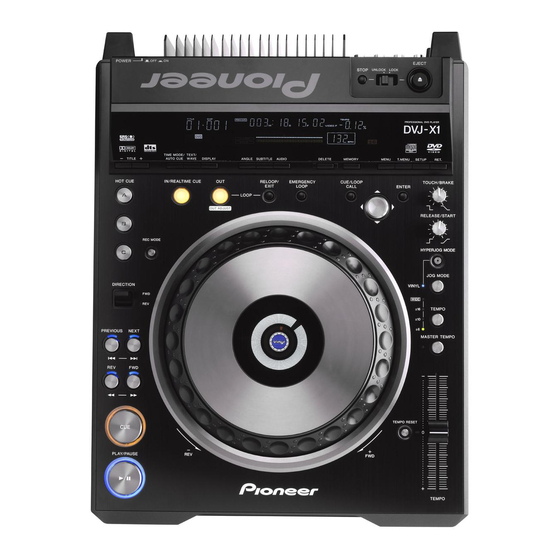
Page 7: Operation Panel
Before Operating (Names and Functions of Parts) Operation panel Buttons and controls with the mark are disabled when the mode select switch is set to NORMAL. Buttons and controls with the mark are disabled when the mode select switch is set to DJ. 7. - Page 8 Before Operating (Names and Functions of Parts) 17. TEMPO control range indicator (±6, ±10, ±16, WIDE) 40. TIME MODE/AUTO CUE button ¶ When control range is set to ±6%, the ±6 indicator lights. TIME MODE: ¶ When control range is set to ±10%, the ±6 and ±10 indicators Each time the button is pressed, the time display switches alter- light.
-
Page 9: Display
Before Operating (Names and Functions of Parts) Display 2 3 4 5 6 7 8 9 29 28 27 26 25 24 23 22 20 19 18 1. Title number (TITLE 00-99) 18. BPM counter display Indicates the DVD title number. Lights to indicate the beats per minute (BPM) of the currently play- Not displayed during CD playback. -
Page 10: Jog Dial Display
34. VINYL mode indicator (Vinyl) Lights when VINYL mode is set to ON. Playing images from the DVJ-X1 on a television set The example shown here is an illustration meant to depict the general display contents, and may differ somewhat from actual monitor appearance. -
Page 11: Usable Discs
Discs Usable with This Unit Types of discs playable on this unit The following discs cannot be played on this unit: DVD video discs not marketed for region “1” or “All” This unit is designed to support NTSC video format; discs or DVD-RW discs recorded in VR format their packaging should include messages indicating that they DVD audio discs... -
Page 12: Block Diagram (Dj Mode)
DVJ-X1 BLOCK CHART (DJ MODE) DVD / IC702 - 703 Giant Slalom Logic Shockproof ATAPI Interface Memory SDRAM SDRAM SDRAM SDRAM SDRAM IC2000 256M × 6 256M × 6 It functions only for the 256M × 2 16M × 1 64M ×... -
Page 13: Block Diagram (Normal Mode)
DVJ-X1 BLOCK CHART (NORMAL MODE) DVD / SDRAM SDRAM IC2000 It functions only for the Progressive 256M × 2 16M × 1 (AN22022A) output in NTSC, and does not function for the Progressive output in PAL. ATAPI IC1511 IC2100 IC701... -
Page 14: Overall Block Diagram 14~15
BLOCK DIAGRAM AND SCHEMATIC DIAGRAM BLOCK DIAGRAM (1/2) DVPL ASSY MAIN ASSY SPINDLE OEIC IC1904-IC1907 CN2001 MOTOR IC702, IC703 K4S641632F-TC75 K4S561632E-TC75 IC2000 256M AN22022A SDRAM ×2 64M SDRAM PICKUP ×4 ASSY CN2007 CN701 VDEC VDEC IC701 CONTROL DATA ATAPI IC903 CN2004 PE5337A PD6649A... - Page 15 IC1301-IC1312 K4S561632E-TC75 MJCB CMPB IC1508 HY57V161610DTC-8 ASSY ASSY 256M 256M 16M SDRAM SDRAM ×6 SDRAM ×6 IC1503 IC1501 TC74HC4053AFT LA73054 CN703 CN4501 CN4506 CN3701 JA3701 IC1511 YOUT C YOUT PM0033A P_CB PROGRESSIVE IC1106 CB/PB P_CR ENCODER XC2S150E-6PQ208C VIDEO MEMORY CR/PR CBOUT C CBOUT C CB...
-
Page 16: Power Supply Block Diagram 16~17
7 Power Supply Block V+5D CN4506 V+5D CMPB MJCB ASSY ASSY CN3701 V+5D CN4509 V+5D DOUT CN4602 ASSY CN101 CN4503 J4502 IC4504 FLAC1 FLAC1 FLAC2 FLAC2 AN4301 J4301 IC4506 FLAC3 FLAC3 LIVE FLAC4 FLAC4 AC IN V+12A VLOAD VLOAD IC4507 V+12A VLED NEUTRAL... - Page 17 MFLB DIPB ASSY EJTB ASSY CN3001 CN3401 ASSY FLAC1 FLAC2 V+5D V+5D V+5D V+5D CN3402 CN3501 V3401 MAIN FL CN3002 JFLB FLAC1 JOGB ASSY FLAC2 CN3003 CN4001 ASSY FLAC3 FLAC3 FLAC4 FLAC4 V+5D V+5D VLED V+5D V+5D VLED CN4002 CN4101 V+5D V4001 V+5D...
-
Page 18: Power On Sequence
POWER ON SEQUENCE Player section MAIN CPU CPU for the Operation section Power on Power on Power on Canceling reset of Canceling reset of the Canceling reset of SODC (IC2100), Pin 45 CPU (IC3004), Pin 12 CPU (IC111), Pin 193 Initial setting for the CPU Initial setting Initial setting for the CPU... -
Page 19: Drive Startup Sequence
Sequence of Starting Up the Drive Note: Install a disc after turning the unit on. Disc installation Focus gain adjustment Detection by the Inside switch is performed only for the first disc. Carriage shifted to the focus position Tracking gain adjustment Canceling offset for FE, TE, AS, PFENV, LNSC, and JIT Tracking open... -
Page 20: Adjustments 20~21
ADJUSTMENT SLDB ZERO POINT ADJUSTMENT 1. SLDB Assy Adjustment Slider Zero Point Adjustment Adjustment Condition Open the control panel and the player is the normal operation state. Set the TEMPO range to ±6%. Adjustment point VR3202 Measurement point TEMPO indication Measuring Instrument None Adjustment Value... - Page 21 2. MAIN Assy Adjustment Master Clock Free-running Adjustment SYNC signal is no input. No disc Adjustment Condition VC1701 Adjustment point Measurement point Frequency counter Measuring Instrument 27MHz ± 20Hz Adjustment Value Adjust VC1701 so that the frequency of TP1 becomes 27MHz ± 20Hz. Procedures Symptom of an adjus Displays are disrupted, not correct, or stop.
-
Page 22: Service Modes 22~31
In this mode, the version of the software program for each microcomputer can be checked. SUB 1.00 In the screen of the each software version, shows the region number on the top right of screen. DVJ-X1 SERVICE MODE 02 MAIN : Ver 1.00... - Page 23 How to quit Service mode Press the MASTER TEMPO button to quit Service mode. List of error codes When an error is detected, one of the following error codes is displayed on the FL display. Error code Description Checkpoint E-7001 ATAPI system (drive) error Check the connection with the player section.
- Page 24 2. Mode for checking buttons and their indications, as well as the load on the JOG dial • To enter this mode, while holding the TEMPO and RET. buttons pressed, turn on the power. • When this mode is entered, "SERVICE" is displayed on the dot matrix section of the FL display. Mode for checking buttons and their indications •...
- Page 25 (FL DISPLAY) : Dot matrix display TOUCH/BRAKE, RELEASE/START, TEMPO slider Indications of read-in values for the TOUCH/BRAKE and RELEASE/START controls and TEMPO slider The read-in values for the TOUCH/BRAKE and RELEASE/START controls and TEMPO slider are displayed as a bar in Area 9 of the FL display: Area "mloop"...
- Page 26 Wait for the unit to start up then enter "IW" to confirm that "R" is returned. If error E11 is returned, wait a few moments then enter "IW" again. 8 Enter "EJ" to eject the disc, then turn off the power of the DVJ-X1 then turn it back on. Check that no error is displayed.
- Page 27 • Start up the terminal software of the PC and set as follows: Communication speed: 4800 bps, parity: none, STOP bit: 1. • Turn on the power of the DVJ-X1 and wait until the "POWER ON" indication disappears. Then press the ENTER key on the PC several times to confirm that "R"...
- Page 28 The commands described here are for testing the mechanical and servo systems, and no audio or video output is available. In the following list of commands, ?? indicates a decimal number. Command Name Description Address Block During CD playback, address mode is set to block. During DVD playback, address mode is fixed at block. Address Track During CD playback, address mode is set to track.
- Page 29 <Supplements> ¶ How to designate an address for a search There are the following four ways of designating an address for a search: Address Block When the BK command is issued, the address mode is set to block (During CD playback: absolute time [AMIN:ASEC: AFRAME], during DVD playback: sector).
- Page 30 The commands described here are for testing the mechanical and servo systems, and no audio or video output is available. In the following list of commands, ?? indicates a decimal number. Command Name Description Address Block During CD playback, address mode is set to block. During DVD playback, address mode is fixed at block. Address Track During CD playback, address mode is set to track.
- Page 31 <Supplements> ¶ How to designate an address for a search There are the following four ways of designating an address for a search: Address Block When the BK command is issued, the address mode is set to block (During CD playback: absolute time [AMIN:ASEC: AFRAME], during DVD playback: sector).
-
Page 32: Disassembly 32~37
DISASSEMBLY Diagnosis of the MAIN Assy Diagnosis of the control panel section Remove the eight screws. Remove the seven screws. Open the bottom case Assy slightly with the MAIN Assy attached so that it can swing open hinged at the bottom. (As the flexible cable to be removed in Step 3 below is not very long, be careful not to open the bottom case Assy too far.) - Page 33 Styling the flexible cable of the SDCB Assy Hook the control panel section onto the chassis, as shown in the photo below. Control panel section CN2502 SDCB Assy Lead tape R4 Fix the flexible cable to the hook with a piece of lead tape R4.
- Page 34 Jog section Remove the five screws. Remove the SW ring by removing the three screws. Disconnect the flexible cable. Remove the jog section by pulling it out toward front. SW ring Control panel section SW spring 31 SW spring 31 Bottom view Jog section Peel the sheet SW off.
- Page 35 Player Section Remove the earth plate by removing the four screws. Notes for replacing the sheet SW Do NOT warp the sheet SW. No dirt or foreign object must be attached to the adhering surface of jog holder 2. If glue remains on the adhering surface, remove it completely using alcohol.
- Page 36 Traverse mechanism G11 Assy-S Remove the DVPL Assy by removing the two screws. Remove the slot-in mechanism G5 Assy by unhooking the four hooks. DVPL Assy Bottom view Disconnect the two connectors and three flexible cables. DVPL Assy Slot-in mechanism G5 Assy Remove the screw.
- Page 37 Cleaning the pickup lens Remove the Weight G11 by removing the three screws. Remove the INSW Assy and inside SW base by removing the screw. Before shipping out the product, be sure to clean the following positions by using the prescribed cleaning tools : Weight G11 Cleaning liquid : GEM1004...
Need help?
Do you have a question about the DVJ-X1 and is the answer not in the manual?
Questions and answers