
Related Manuals for A.J.S. 8, 14

Summary of Contents for A.J.S. 8, 14
- Page 1 INSTRUCTION BOOK 250 c.c. O.H.V. MODEL 14 350 c.c. O.H.V. MODEL Issued by A.J.S. MOTOR CYCLES L O N D O N S.E.18 Proprietors: ASSOCIATED MOTOR CYCLES LTD.
- Page 3 INSTRUCTION BOOK A•J•S MODEL 14-250 c.c. O.H.V. MODEL 14/CS 250 c.c. O.H.V. SCRAMBLER MODEL 8-350 c.c. O.H.V. Factories: BURRAGE GROVE and MAXEY ROAD PLUMSTEAD, S.E.18 Telephone: WOOlwich 1223 (7 lines) Telegrams: "ICANHOPIT, WOL-LONDON" Cables; "ICANHOPIT, WOL-LONDON" TELEX 22617 Codes: A.B.C. 5th and 6th Edition; Bentley's; and Private Codes Registered Offices: PLUMSTEAD ROAD,...
-
Page 4: Table Of Contents
CONTENTS Page … … … … … … … … … … Carburetter … … … … … … … … … … Controls … … … … … … … … … … … Data … … … … …... - Page 5 HE MODERN MOTOR CYCLE unquestionably provides one of the most healthy, economical and pleasant means of transport. addition, by reason of its superb braking, high power to weight ratio and ease of control it is, if used with due care, one of the safest vehicles on the road.
-
Page 6: Data
Data 350 c.c. Identity … … … … … Engine Number On the crankcase near engine plate cowling … … … … … … … Frame Number On right side of frame head lug … … … … … … …... -
Page 7: Ignition Timing
Data 250 c.c. Identity … … … … … Engine Number On the crankcase near engine plate cowling … … … … … … … Frame Number On right side of frame head lug … … … … … … …... -
Page 8: Technical Data
250 SCRAMBLES MODEL. TECHNICAL DATA. … … … … … 248 c.c. Engine capacity … … … … … 70 x 65 mm. Bore and stroke … … … … … 11·5 : 1 Compression ratio … … … 376/250 Carburetter AMAL Monobloc …... -
Page 9: Controls
Controls Throttle twist grip. On right handlebar. Twist inwards to open. When fully closed engine should just idle when hot. Valve Lifter. Small lever on left side handlebar. Air lever. Small lever on right handlebar. Pull inwards to increase air supply to carburetter. -
Page 10: Driving
Driving FUEL Although various quality fuels are again available owners are advised to use only the best. The small economy that might be considered to accrue by using the cheaper grades is more than offset by the advantages obtained by using only Premium Grades. FUEL SUPPLY Two fuel feed taps are situated underneath the rear end of the petrol tank. - Page 11 To engage a higher gear the pedal is pressed downward with the toe and a lower gear is obtained by raising the pedal with the instep. To engage first gear from the neutral position, the pedal is therefore raised. After each pedal movement, internal springs return the pedal to its normal horizontal position.
-
Page 12: Lubrication
Lubrication LUBRICANTS TO USE Efficient lubrication is of vital importance and it is false economy to use cheap oils and greases. The use of multigrade oils is not recommended. We recommend the following lubricants to use in machines of our make. FOR ENGINE LUBRICATION COLD EXTREME COLD... -
Page 13: Engine Lubrication System
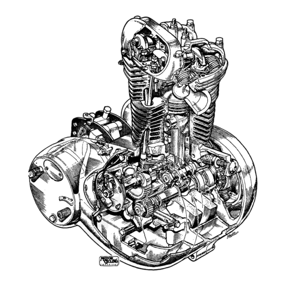
CHECKING OIL CIRCULATIO N Provision is made to observe the oil circulating, which is visible after removing the oil filler cap on the right side of the crankcase. Illustration 1 Cut-away section of engine ENGINE LUBRICATION SYSTEM This is by true dry sump system. The oil tank, or reservoir, is integral with the crankcase. - Page 14 ENGINE OIL PUMP (see Illustration 1) If, for any reason, the crankcase is dismantled the oil pump plunger must be removed from its housing before attempting to separate the crankcase halves. It is also necessary to remove the small timing pinion. I M P O R T A N T Under no circumstances must either the pump plunger or guide screw be disturbed in ordinary routine maintenance.
-
Page 15: Rear Brake Pedal
E X H A U S T VALVE STEM LUBRICATION From a drilling in the exhaust rocker axle boss in the rocker box, oil is fed to a cavity in the cylinder head. A further drilling from this cavity, through the cylinder head to an oil hole in the valve guide, provides positive lubrication for this part of the engine and needs no adjustment. -
Page 16: Maintenance
Maintenance PERIODICAL M A I N T E N A N C E Regular maintenance attention to lubrication and certain adjustments must be made to ensure unfailing reliability and satisfactory service. This necessary attention is detailed below and owners are strongly recommended to carefully follow these suggestions and to make a regular practice of doing so from the first. -
Page 17: Engine
Engine Service TAPPET ADJUSTMENT The top ends of the two long push rods have screwed extensions. These are locked in position by nuts, thereby providing tappet adjustment. The correct tappet clearances, with valves closed and engine warm (not hot) is N I L . This means the push rods should be free enough to revolve and, at the same time, there should be no appreciable up and down play. - Page 18 TO REMOVE T W I N SEAT Remove two bolts under the rear end of the seat, release the nuts securing the front portion of the seat, which now can be lifted off. TO REMOVE THE PETROL T AN K Close both petrol taps, unscrew the two cap nuts securing the petrol pipe (watch for 4 fibre washers each side of the banjo unions).
- Page 19 Illustration 3 The valve guides and the needle adjusting screw are also shown withdrawn PLAIN HOLE, FOR OIL FEED TO INLET PLAIN HOLE, FOR OIL FEED TO EXHAUST VALVE. VALVE. TAPPED HOLE, ACCOMMODATE HOLE, TO ACCOMMODATE DOWEL PIN CARBURETTER RETAINING STUD. LOCATING VALVE SPRING SEAT.
- Page 20 REMOVING THE CYLINDER A N D PISTON With the cylinder head removed, the barrel can be raised vertically to clear the holding down studs. Before doing so, position the engine with the piston on the top of its stroke, have available a piece of clean rag. Raise the cylinder sufficiently to enable the rag to be put into the throat of the crankcase (under the piston) as a precaution against a broken ring falling into the crankcase, then lift the cylinder clear of the four studs passing...
- Page 21 REFITTING THE CYLINDER BARREL Fit a new cylinder base gasket, after removing broken pieces of the old one. Use a little jointing compound on the base of the cylinder and stick a new gasket to it, no jointing compound should be on the crankcase face. Set the piston ring gaps at 120°, pass the cylinder over the four long studs and lower it gently at the same time compressing each piston ring in turn with the fingers, until the cylinder has passed the scraper ring when it can be lowered on to the crankcase.
- Page 22 Illustration 5 Automatic Ignition Advance Mechanism (Approximate Ignition Setting) TO CHECK THE T I M I N G Position the engine as detailed for tappet adjustment. Remove the sparking plug, the cover for the contact breaker and engage top gear. Obtain a short length of stiff wire or wheel spoke about 5"...
- Page 23 TO RESET I G N I T I O N T I M I N G As the ignition advance is limited to ¼" B.T.D.C, this setting is critical and must be carefully carried out. The automatic ignition control unit is a taper fit on the camshaft, retained by a central bolt.
-
Page 24: Carburetter
Carburetter Service The information given in this section includes all that will normally be required by the average rider. For further details, particularly those connected with racing and the use of special fuels, we refer the enquirer to the manufacturers of the carburetter, Amal Ltd., Holford Road, W i t t o n , Birmingham, 6. - Page 25 Illustration 6 Carburetter details in assembly order...
-
Page 26: Air Filter
AIR FILTER In locations, such as the United Kingdom, where the roads and atmosphere are particu- larly free from dust, it is not considered necessary to have an air filter fitted to the carburetter, but in countries where the atmosphere contains a very heavy dust content, an air filter is essential in order to prevent abrasive wear. -
Page 27: Transmission
Transmission Service T H E GEAR B O X The gear box, cylindrical in shape, is housed in an arc machined on the crankcase, and retained by two high tensile steel straps. As the gear box mainshaft is eccentric to the gear box shell, partial movement of the gear box in its housing provides latitude for front chain adjustment. - Page 28 DISMANTLING THE KICKSTARTER When the gear box cover is removed, the kick-starter mechanism will come out with the cover. The face ratchet pinion is under tension of the ratchet spring, to remove this pinion temporarily fit the kick-starter crank and relieve the spring tension, the pinion will then be released.
- Page 29 TO REMOVE CHAINCASE OUTER COVER Use a tray under chain case to catch oil. Remove drain plug, Remove near side footrest. Remove engine plate cowling (two screws). Remove three snap connectors on wire in BLACK sheath, push the sheath towards the chain case a small amount.
-
Page 30: Clutch Adjustment
TO REPLACE CLUTCH CONTROL CABLE Reverse the above instructions and, finally, adjust as detailed earlier. Locate the cable in front of the gear box clamp bolt. CLUTCH ADJUSTMENT Attention to the clutch is usually confined to adjustment of the operating mechanism. To avoid clutch slip or clutch drag, it is essential to have x of an inch free movement between the clutch outer casing and the clutch cable adjuster. - Page 31 C L U T C H SPRING ADJUSTMENT In the event of clutch slip, first ascertain that the operating mechanism is correctly adjusted (see clutch adjustment). After dismantling the clutch, when refitting the clutch spring adjusting nuts, they should be screwed on until the spring stud just protrudes through the bottom of the recess in the adjuster nut.
-
Page 32: Forks And Frame
Fork and Frame Service 250 c.c. MODEL STEERING HEAD ADJUSTMENT With the machine on the stand, need for adjustment of the steering head bearings may be detected by trying to rock the forks with hands holding the fork legs. The bearings should be tested for slackness after the first 200 miles and subsequently every 1,000 miles. - Page 33 FORK " H " MEMBER 043343 SCREW, INNER TUBE, TOP 043245 000201 WASHER, FIBRE, INNER TUBE TOP SCREW TUBE, COVER, TOP, LEFT A N D RIGHT 043345-6 ADAPTOR, INNER TUBE TOP SCREW 043246 SPRING, MAI N 043259 043251 SCREW, TOP COVER TUBE A N D DRAIN PLUG WASHER, SHAKEPROOF COVER...
-
Page 34: Front Forks
350 c.c. MODEL STEERING HEAD ADJUSTMENT The steering head bearing must be kept in close adjustment otherwise if movement develops which is not promptly corrected damage can occur to the ball-races. To make this adjustment the front wheel must be raised clear of the ground by using a box under the crankcase or two boxes, one placed under each footrest. - Page 35 Illustration 12 350 c.c. Front Forks For description see page 34...
- Page 36 DESCRIPTION REF. N O . WASHER, LEATHER, FOR FORK SPRING TOP SEATING. BUFFER, RUBBER, FOR FORK INNER TUBE (ONE OF THREE). SPRING. M A I N , FOR FRONT FORK. BUFFER, RUBBER, FOR FORK INNER TUBE (ONE OF THREE). BUFFER, RUBBER, FOR FORK INNER TUBE (ONE OF THREE). WASHER, LEATHER, FOR FORK SPRING BOTTOM SEATING.
-
Page 37: Rear Suspension
Illustration 13 "Ghost" view of Rear Suspension Unit REAR SUSPENSION The rear wheel is mounted in a fork which is hinged just behind the gear box. The fork works in bronze bearings and is lubricated by an oil reservoir around the bushes and this can be replenished with heavy gear oil (SAE 140) by means of a grease nipple situated above the pivot on the right hand side. -
Page 38: Centre Stand
Maintenance is confined to external cleaning and occasional greasing of the cam ring adjuster. Should a squeak or rubbing noise develop as the units move, remove in turn each unit, uncover the spring by removing the top split collars, grease the external diameter of the springs and reassemble. -
Page 39: Wheels And Brakes
Wheels and Brakes TO REMOVE THE FRONT WHEEL (350 c.c. Model) With the front wheel clear of the ground, disconnect the front brake cable, then remove the nut that secures the brake torque arm to the front brake cover plate. Release the four nuts (No. - Page 40 Illustration 14 Front Hub Assembly...
- Page 41 Illustration 15 Rear Hub Assembly...
- Page 42 Electrical Service GENERAL The lighting and ignition systems are combined, using a six pole permanent magnet excited A.C. generator, which charges the battery via a selenium rectifier. The remaining electrical units are fed from the battery in the normal manner. The alternator unit has inherent regulating properties which combined with circuit switching gives the correct charge rate under all conditions.
- Page 43 C O N T A C T BREAKER U N I T This unit comprises the contact set, condenser and cam lubricating pad. The contacts are adjusted by releasing the locking screw and then setting the distance by a slight movement of the eccentric screw whilst the rocker arm heel is on the peak of the cam lobe, and finally tightening the locking screw firmly.
- Page 44 SPARKING PLUG (SINGLE OR 3-POINT) The K.L.G. Type FE80 "Corundite" Plug is fitted to all models. It has a thread of 14 mm. and the reach is ¾". The point gap is ·020 to ·022°. Check the point gaps every time the engine is decarbonised and, if necessary, re-set the points. See that the plug is fitted with its external seating washer.
- Page 45 Temperature of filling room, battery and electrolyte should be maintained between 60° F. and 80° F. Batteries filled in this way are 90 per cent. charged. After filling, a dry charged battery needs only the attention normally given to lead-acid type batteries. BATTERY M A I N T E N A N C E .
- Page 46 Illustration 20 Wiring Diagram: 250 c.c. Scrambler...
- Page 47 Illustration 21 Wiring diagram: 250 c.c. Scrambler (with lights removed)
- Page 48 Illustration 22 Wiring diagram (Model 8 and 14)
-
Page 49: Information
Useful Information TRACING TROUBLES Engine fails to start, or is difficult to start, may be due to: Carburetter flooded unnecessarily. Water on high-tension cable. Moisture on sparking plug. Oiled up, or fouled, sparking plug. Throttle opening too large. Pilot jet choked. A i r lever in open position or bad air leak at carburetter joint. - Page 50 EXCESSIVE OIL C O N S U M P T I O N Excessive oil consumption may be due to: Badly worn, or stuck up, piston rings. (Causing high pressure in the crankcase). Worn valve stems. EXCESSIVE PETROL C O N S U M P T I O N Excessive petrol consumption may be due to: Leaks in the petrol feed system.
-
Page 51: Repairs And Service
Repairs and Service REPAIRS The instructions regarding repairs should be clear and definite, otherwise the cost may be greater than that expected. We shall be pleased to give estimates for repairs if parts are sent to us for that purpose. If the estimate is accepted, no charge is made for the preliminary examination, but, should it be decided not to have the work carried out, it M A Y be necessary to make a charge to cover the cost of whatever dismantling and... - Page 52 The Registration Book and the Licence Disc will bear the registration numbers that have been allotted to your machine and will also show the date the Road Licence expires. Your number plates must then be painted, in white upon a black background, with the registration numbers in characters of even thickness as follows: The numbers on the front plate must be 1¾"...
- Page 53 T H E DRIVER A N D T H E LAW The driver of a motor cycle M U S T be I N S U R E D against Third Party Claims and M U S T be able to produce an I N S U R A N C E CERTIFICATE showing that such an insurance is in force.
-
Page 54: Free Service
Free Service Scheme FREE SERVICE SCHEME All owners of NEW MODELS are entitled to one FREE SERVICE A N D I N S P E C T I O N at 500 miles, or, at latest, three months after taking delivery. This service is arranged by the supplying dealer to whom the Free Service Voucher must be handed. -
Page 55: Spare Parts
Spare Parts ENUINE SPARE PARTS purchased from an Authorised Dealer, or from the Factory, are identical with the parts originally built into your motor cycle. By using them you are assured that they will fit accurately and give satisfactory service. SPARES STOCKISTS For the convenience of owners Spares Stockists are appointed for most districts. -
Page 56: Tools And Special Equipment
Tools and Special Equipment TOOLS The standard tool kit, issued with each new machine, contains: 017253 Tool Roll. 017007 Tyre Lever. 017114 Pump. 017249 Adjustable Spanner. 017257 8 " x x " Spanner. 017052 x " x 4 " Spanner. c "... -
Page 57: Guarantee
GUARANTEE In this Guarantee the word "machine" refers to the motor cycle, scooter, motor cycle combination or sidecar as the case may be purchased by the Purchaser. In order to obtain the benefit of this Guarantee, the Purchaser must correctly complete the attached registration form and return it to us within fourteen days of the purchase.
Need help?
Do you have a question about the 8, 14 and is the answer not in the manual?
Questions and answers