Table of Contents
Advertisement
Advertisement
Table of Contents

Related Manuals for MALA Easy Locator Pro HDR Series


Summary of Contents for MALA Easy Locator Pro HDR Series
- Page 1 MALÅ Easy Locator Pro HDR Series User Manual...
- Page 2 MALÅ Easy Locator Pro HDR Series User Manual Guide f or O perating t he M ALÅ E asy L ocator P ro HDR G round P enetrating R adar ...
- Page 3 MALÅ Geoscience Under the copyright laws, this manual may not be copied, in whole or in part, without the written consent of MALÅ Geoscience. Your rights to the software are governed by the accompanying software license agreement. The MALÅ Geoscience logo is a trademark of MALÅ...
-
Page 4: Table Of Contents
Table of Contents Preface About this Manual Additional Resources Feedback Safety and Compliance Notices Get Ready. Set up. Go MALÅ HDR Features Accessories and Optional Features Unpack. Inspect. Register Repacking and Shipping Registering MALÅ HDR System Assembly and Set Up Hardware Assembly Connecting it all up Antenna LED Indicators... -
Page 5: Preface
Preface About t his M anual This manual is written for the end user of the product and explains how to set up and configure the product, as well as providing detailed instruction on its use. Basic theory for Ground Penetration Radar is outlined to help the operator understand the underlining technology. -
Page 6: Safety And Compliance Notices
Safety a nd C ompliance U ser N otices This GPR-device is certified according to FCC, subpart 15, IC RSS-220 and ETSI EN 302 066-1&2. According to the regulations stated in ETSI EN 302 066-1 (European Telecommunication Standards Institute): The control unit should not be left ON when leaving the system unintended. -
Page 7: Get Ready. Set Up. Go
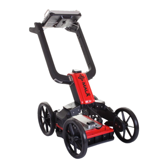
MALÅ E asy L ocator P ro H DR F eatures The HDR-series (High Dynamic Range) is the latest addition to MALA’s versatile product range. It is a completely new design, based on patented cutting edge technology. These new antennas are not just an upgrade of earlier designs;... -
Page 8: Accessories And Optional Features
Accessories a nd O ptional E xtras Additional Battery and battery charger Additional Li-ion Battery Pack 12 V (3.5 Hour) for the MALÅ Easy Locator Pro. Additional MALÅ Li-ion Battery Charger ... -
Page 9: Unpack. Inspect. Register
Unpack. I nspect. R egister Great care should be taken when unpacking the equipment. Be sure to verify the contents shown on the packing list and inspect the equipment and accessories for any loose parts or other damage. -
Page 10: Repacking And Shipping
Repacking a nd S hipping The MALÅ Geoscience packing kit is specially designed for shipping MALÅ Easy Locator Pro HDR. The packing kit should be used whenever shipping is necessary. If original packing materials are unavailable, pack the instrument in a box that is large enough to allow at least 80mm of shock absorbing material to be placed all around the instrument. -
Page 11: System Assembly And Set Up
System A ssembly a nd S et U p MALÅ Easy Locator Pro is an integrated system, consisting of an Easy Locator controller and HDR antenna, linked through a single data/power cable. Hardware ... - Page 12 Raise t he H andle Release the main handle assembly clamp Pull one side of the handle assembly out of out of its fixed position. Once released, do the same on the opposite side. ...
- Page 13 Fasten the clasp on the rear of the handle assembly Slacken the bolt on the rear of the controller, raise the controller to the desired viewing angle and re-tighten the bolt. Adjust the four straps to raise or lower the antenna to the required height ...
-
Page 14: Connecting It All Up
Connecting i t a ll u p Connect the data cable to the Easy Locator Pro controller Note: L ook for the countersink in the power cable and place it towards the mark on the connection. Push lightly. - Page 15 Connect the encoder cable from the wheel to the antenna. Note: T he precision of the encoder wheel depends on several factors, such as; the condition of measurement surface, the pressure applied on the wheel and possible wear. Warning: ...
-
Page 16: Antenna Led Indicators
Antenna L ED I ndicators Three LED-indicators are mounted beneath the antenna product label. DATA: Continuous flashing light indicates the unit is working properly and ready for data collection. Irregular flashing on this LED means erroneous antenna configuration or possible software version issue. -
Page 17: Charging The Batteries
Charging the Easy Locator Pro Battery With the use of the correct adaptor, connect the supplied battery charger to the battery pack. The LED light on the charger indicates the following: Red = Charged < 80% Yellow = Charged 80-100% Green = Maintenance charging When re-mounting the battery, gently attach the d-sub connector on front of the battery with the d-sub on the mounting tower. -
Page 18: User I Nterface
User I nterface The following sections contain a detailed description of the user interface and give tips and warning designed to help the user achieve the highest possible level of productivity and safety while operating the MALÅ Easy Locator Pro HDR. ... -
Page 19: Main Display Window
Main D isplay W indow The MALÅ Easy Locator Pro Controller uses dedicated software designed specifically for the display and collection of GPR data. Note: T he Controller utilizes a sunlight readable LCD display for maximum visibility in sunlight. Navigating ... -
Page 20: Main Menu
Main M enu The items available under the Main M enu v ary depending whether the system is in Stopped m ode o r Started m ode. Stopped m ode: ... -
Page 21: Zoom Function
Zoom F unction Use the Navigator t o select the Vertical s crollbar. The vertical scrollbar turns yellow when selected. Push the Navigator o nce to activate scrolling. The Vertical s crollbar w ill turn blue indicating that it has been activated. -
Page 22: Main Menu Icons
The Full screen button toggles the display to full-screen mode where the menu and status information is hidden and the entire display is used to display the GPR profile Note: P ressing the Navigator again returns the display to the default with the menu included. The Background removal filter button is used to remove horizontal lines/reflections caused by noise from the GPR profile. -
Page 23: Measurement Parameter Menu
Measurement P arameters M enu Depth defines the length of the radargram vertical scale. This is sometimes refered to as the time window length. In this case, the velocity measuremt is used to calculate the depth window. Note: This measurement will vary if the velocity measurement parameter is changed. - Page 24 Set the type of trigger to be used for initiating a measurement. Three triggering options are available: Wheel, Time, or Keyboard Triggering. Note: Changing the three different trigger options will change the options listed below the Acquisition Mode icon Note: When measuring by time, make sure that the time interval is appropriate.
-
Page 25: Acquisition Parameters Menu
Acquisition P arameters M enu Choose Forward or Backward depending on the direction of the scan whilst utilising the Measuring Wheel or Cart. Note: This option will not be available when Time or Keyboard Triggering is selected on the Measurement Parameters Menu Select the Wheels Edit and Calibration to enter the wheels calibration menu. -
Page 26: Wheels Edit And Calibration Menu
Wheels E dit a nd C alibration M enu Choose the Select Wheel to highlight the wheel to be edited or deleted from the list. The Create New Wheel option allows the user to select a new type of wheel in addition to the standard list. -
Page 27: Wheels Edit Options
Wheels E dit O ptions Select Wheel Name to create a name for the new wheel. Select Forward or Reverse depending on the direction of the wheel during the calibration process. Measure a distance on the ground using a measuring wheel or tape. Enter this distance after selecting Distance for Calibration. -
Page 28: Display Parameters Menu
Display P arameters M enu The palette refers to the display of the radargram, there are 3 options; grey scale or 2 color options. If Trace view is ON, a small window will appear during measurements, showing the actual measured trace. The intensity of the screen light can be changed with the backlighter option. -
Page 29: Operating I Nstructions
Operating I nstructions The following sections walk you through more advanced modes of operation of the equipment. 2D P roject 30 3D G rid P roject ... -
Page 30: 2D P Roject
2D P roject Select 2D Project from the main screen options to conduct a simple 2D profile Select New to begin the measurement. See Main Menu section for a full description of the icons. Note: Check Settings before commencing a measurement Various markers can be inserted into the radargram by selecting the Markers icon... - Page 31 Object Marker allows a similar marker to the surface marker to be placed at a selected depth within the radargram. Reverse the Easy Locator antenna over the feature and select Object, a crosshair will appear on the vertical curser which can be positioned at the correct depth by using the Navigator control.
-
Page 32: 3D G Rid P Roject
3D G rid P roject Grid Project is a tool that makes the visualization of radar data measured in two perpendicular directions easier. A typical Grid project can be used to map a larger area where the direction and location of utilities for instance is unknown. - Page 33 First enter the size of your grid. Using the Navigator, select and edit the X- size and Y-size. Then select and enter the Point Interval for the measurement between the traces. Next select and enter the Line Spacing for the measurement between each profile.
- Page 34 As the antenna is moved forward, a black line indicates the progressing along the grid line If a mistake is made during the measurement or the line is not completed, select Stop and then Next Line, an option will appear to restart the line.
- Page 35 Select the Settings Icon to proceed to the next step. Select Background Removal option to On if removal of horizontal lines in the dataset is required. Next, select Migration Wizard, this enables the correct velocity setting to obtain the best possible top view. Next, choose an X or Y cross-section with a well-defined hyperbola.
- Page 36 Finally, select the Quit button to exit and apply the migration to the entire data set. Select the X-Section button to view the X-axis data in the side view. When activated, use the Navigator to scroll across the data set. Select the Y-Section button to view the Y axis data in the side view Select the Depth button and use the Navigator to scroll through the time slices in the top view window...
-
Page 37: 3D P Roject S Ettings M Enu
3D P roject S ettings M enu Change the color scheme for the GPR profiles. Three options are available, a grey scale and two different color schemes. Set the velocity based on soil type. Setting the velocity allows the adjustment of the depth scale for differing soil conditions. - Page 38 Select the correct level of backlight for the ambient light levels. This setting can be adjusted within the range of 0–100%. Tip: Reducing the backlight will extend the battery life between charges. The Background removal filter button is used to remove horizontal lines/reflections from the GPR profile.
-
Page 39: Object Mapper Project
ObjectMapper P roject An Object Mapper Project is a tool to easily handle and interpret radar profiles acquired with the Easy Locator Controller, where a number of radar profiles are linked to a common baseline or positioned with GPS. See the examples below. - Page 40 Select Settings to apply correct measurement values. See Measurement Parameters Menu for full details Select New Project to start the project and move onto the following screen Select Project Name to tag a name to the project. Use the Navigator to enter the name, one character at a time.
-
Page 41: Object Mapper Measurements With Baseline
Object M apper M easurements w ith B aseline When the Start the project button is pressed, the Start Profile screen appears Once Start Profile is pressed, the user returns to the ordinary measurement screen. The additional Baseline Crossing icon will be active on this screen. - Page 42 Key: 1: Orientation to baseline start point. In this case it is 270 degrees. 2: Distance from the start of the current profile to the baseline 3: Distance from baseline start to the current profile 4: Previous distance First set the distance from the baseline start point to the current profile. The select the angle of the profile to the baseline start point.
-
Page 43: Object Mapper With Gps
Object M apper m easurements w ith G PS To create a project with GPS positioning, start a new project and select the GPS Positioning to On and select Start the Project Next, select start profile and the screen will return to the main measurement screen. -
Page 44: Continuing An Object Mapper Measurements Project
Continuing a n O bject M apper m easurements P roject To continue a previously started ObjectMapper Project select Continue OM Project in the Project Main screen. Use the Navigator to choose between the Object Mapper Projects and press the button to continue the selected Project. - Page 45 Select the Hardware Tests icon to enter the hardware test screen. Select Start Test or Start Ethernet Test to start the self-test procedure. Each item of hardware will be tested sequentially with the results of each tested displayed on the screen and written to a file. Once the test is completed, select Upload “test_results.jpeg”...
-
Page 46: Gps Options And Settings
Select the Restore Factory Settings option and press to perform a reset when experiencing problems, or if you would like to reset the settings to the default factory settings. A confirmation dialog is displayed before reset operation is performed. Select Next Screen to access additional System Menu options. Default Start Depth value determines the depth widow at start of a scan. - Page 47 1. Built-in, this option selects the built-in DGPS module. Select the correct SBAS Region for your area. Currently available options are listed below 2. COM Port, this option is selected for a RTK GPS input via the COM port. An external RTK GPS antenna can be mounted on the antenna.
-
Page 48: Maintenance A Nd T Roubleshooting
Troubleshooting - Frequently Answered Questions MALÅ Easy Locator Pro HDR has been design to be robust and reliable under adverse conditions. If you encounter a mechanical failure that cannot be fixed on site, please contract MALÅ Geoscience or your MALÅ Geoscience representative for advice. System Malfunctions Most malfunctions are power/data communications or user settings related. -
Page 49: Glossary
Glossary Auto-Gain Similar to Time-Gain except the software decides the coefficients to be applied to give a response across the depth range without over amplifying the trace. Background removal Background removal is used to remove horizontal and nearly horizontal features in the radargram by subtracting a calculated mean trace from all traces, sample by sample. - Page 50 Navigator The push-turn knob fitted to the MALÅ Monitors & Easy locator Controller that acts in a similar way to a computer mouse allowing the user to navigate menus and update data. Rotating the knob either allows sequential scrolling through menu options to make a menu selection or changes selected parameter values.
- Page 51 Time-Gain Time-Gain applies a time-varying gain to compensate for amplitude loss due to spreading and attenuation. The trace is multiplied by a gain function combining linear and an exponential gain, with coefficients set by the user. Trace A "trace" is a single, vertical column of GPR data, representing the signal "traced" by a radar pulse as it travels from the instrument into the subsurface.
Need help?
Do you have a question about the Easy Locator Pro HDR Series and is the answer not in the manual?
Questions and answers