Table of Contents
Advertisement
Quick Links
Plus
FireNET
Analog Addressable Fire Alarm System
Installation and Operation Manual
Hochiki America Corporation
7051 Village Drive, Suite 100
Version 1.073
Buena Park, CA 90621-2268
Created: 12/23/08
714.522.2246 Corporate Headquarters
Updated: Feb 2015
800.845.6692 Technical Support
http://www.hochiki.com
PN# 1700-10840
Advertisement
Table of Contents
Troubleshooting

Subscribe to Our Youtube Channel
Related Manuals for Hochiki America Corporation FireNET Plus

Summary of Contents for Hochiki America Corporation FireNET Plus
- Page 1 Plus FireNET Analog Addressable Fire Alarm System Installation and Operation Manual Hochiki America Corporation 7051 Village Drive, Suite 100 Version 1.073 Buena Park, CA 90621-2268 Created: 12/23/08 714.522.2246 Corporate Headquarters Updated: Feb 2015 800.845.6692 Technical Support http://www.hochiki.com PN# 1700-10840...
-
Page 2: Table Of Contents
Table of Contents Table of Contents ........................... 2 Prefix – Programming Compliance with UL864 9 Edition ............6 Section 1 – Introduction ................................. 7 1.1 Basic Features ......................7 1.2 System Devices and Equipment ................8 1.2A System Devices BOSCH ..................10 ... - Page 3 Section 4 – Expander Board Installation ............................... 38 4.1 Compatible Expander Boards ................38 4.2 General Installation of RS-485 Bus Devices ............38 4.2.1 Wiring Distance and Mounting Locations............38 4.2.2 Addressing ......................39 4.2.3 Terminating ....................... 39 ...
- Page 4 5.18 AMS Addressable Manual Pull-Station ..............82 Section 6 - Network Connections ............................... 83 6.1 Compatible Network Devices................. 83 6.1.1 FN-4127-NIC Network Interface Card .............. 84 Section 7 - Basic Front Panel Operations and Programming ..........88 (Access Level 1, 2, and Real-Time Operation) ...............................
- Page 5 8.1 Access Level Overview ..................108 8.1.1 Entering Access Level 3 ................. 108 8.2 Access Level 3 Menu ..................109 8.2.1 Edit Configuration ................... 109 8.2.4 Print Configuration ..................120 8.2.6 Loop Data Test ....................121 ...
-
Page 6: Prefix - Programming Compliance With Ul864 9
Prefix – Programming Compliance with UL864 9 Edition Notice to Users, Installers, Authorities Having Jurisdiction, and other involved parties This product incorporates field-programmable software. In order for the product to comply with the requirements in the Standard for Control Units and Accessories for Fire Alarm Systems, UL 864 9 Edition, certain programming features or options must be limited to specific values or not used at all as indicated below. -
Page 7: Section 1 - Introduction
Section 1 – Introduction The FireNET Plus is an analog addressable fire alarm system that meets the requirements of UL 864 9 Edition. 1.1 Basic Features The basic FireNET Plus control panel includes one SLC (Signaling Line Circuit) loop. The loop is capable of supporting 127 analog addressable points which can be any combination of sensors and modules. -
Page 8: System Devices And Equipment
1.2 System Devices and Equipment The following boards, expanders and devices are available from Hochiki America Corp. to be used with the FireNET Plus analog addressable fire alarm system. For a complete description and installation instructions of each product, please see the appropriate section of this manual and the literature supplied with the device itself. - Page 9 DH99-AR Analog Duct Smoke Detector w/Relay MS-RA, MS-RA/R, MS- Remote Test Station for DH98A & DH98AR KA/R FRCME-4 Input Module 4” Box Mount FRCME-M Mini Input Module w Terminal Block FRCMA, FRCMA-I Class A Input Module 4” Box Mount (FRCMA-I has built-in SCI) Supervised Output Module SOM-A, SOM-AI Class A Supervised Output Module (SOM-AI has built-in SCI)
-
Page 10: A System Devices Bosch
1.2A System Devices BOSCH The following boards, expanders and devices are available from BOSCH to be used with the FireNET Plus analog addressable fire alarm system. For a complete description and installation instructions of each product, please see the appropriate section of this manual and the literature supplied with the device itself. -
Page 11: B System Devices Silent Knight
1.2B System Devices Silent Knight The following devices are available from Silent Knight to be used with the FireNET Plus analog addressable fire alarm system. For a complete description and installation instructions of each product, please see the appropriate section of this manual and the literature supplied with the device itself. -
Page 12: C System Devices Fike
1.2C System Devices Fike The following devices are available from Fike to be used with the FireNET Plus analog addressable fire alarm system. For a complete description and installation instructions of each product, please see the appropriate section of this manual and the literature supplied with the device itself. -
Page 13: D System Devices Napco
1.2D System Devices NAPCO The following devices are manufactured by Hochiki America for Napco The following devices are available from NAPCO to be used with the FireNET Plus analog addressable fire alarm system. For a complete description and installation instructions of each product, please see the appropriate section of this manual and the literature supplied with the device itself. -
Page 14: E System Devices Ves
1.2E System Devices VES The following devices are available from VES to be used with the FireNET Plus analog addressable fire alarm system. For a complete description and installation instructions of each product, please see the appropriate section of this manual and the literature supplied with the device itself. - Page 15 NOTE: The VF6001 has been tested to UL 864 8 edition. However, VF6001 will operate with the 9 edition listed FireNET Plus Fire Alarm Control panel. Therefore, it may be used in panel retrofit applications, subject to approval by your AHJ. FireNET Plus I & O Manual Version 1.073...
-
Page 16: System Replacement Parts
1.2.1 System Replacement Parts Control Panel Repair / Replacement Parts FNP-1127-BO FireNET 1127 Control Unit Board Only FNP-1127D-BO FireNET 1127 Control Unit Board Only, with integrated DACT FNP-1127E-BO FireNET 1127 Control Unit Board Only, expandable FireNET 1127 Control Unit Board Only, expandable with FNP-1127DE-BO integrated DACT FNP-1127-ENC... -
Page 17: Master Part Number Schema
1.22 Master Part Number Schema H ochiki America Panel PN B reakdow n -2 127 U S00C This is panel Color & Style This is whether panel is expandable Feature 1 [Network Card / Dialer] This is the Language This is the Device Range This is the number of loops on the product This is the product style Option Ranges Option Type Valid Entries Description Product Style FireNET Plus 1 Loop Hochiki Protocol Loops 2 Loop Hochiki Protocol Device Range 127 Points Language US English None Feature 1 N etw ork Card Network Card, ... -
Page 18: Limitations Of Fire Alarm Systems
1.3 Limitations of Fire Alarm Systems Follow Recommended Installation Guidelines: To achieve early fire detection, fire detection sensors should be installed in all rooms and areas of a house, apartment, or building in accordance with the recommendations of the National Fire Protection Association Standard 72 (NFPA 72), manufacturer’s recommendations, state and local codes, and the recommendations contained in Guide for the Proper Use of System Smoke Detectors, which is made available at no charge to all installing dealers. - Page 19 Limitation on Fire Alarm Effectiveness: A fire alarm system may not provide timely or adequate warning, or simply may not function, for a variety of reasons. For example: No Detection: Particles of combustion or smoke from a developing fire may not reach the sensing chambers of smoke detectors because: 1.
- Page 20 should be provided to warn these people). Any warning device may fail to alert people with a disability, deep sleepers, people who have recently used alcohol or drugs, or people on medication or sleeping pills. Strobes: Strobes can under certain circumstances, cause seizures in people with conditions such as epilepsy.
-
Page 21: Agency Listings, Approvals, Requirements
1.4 Agency Listings, Approvals, Requirements 1.4.1 Federal Communications Commission (FCC) The FireNET Plus has been verified to comply with FCC Rules Part 15, Class A Operation is subject to the following conditions: 1. This device may not cause radio interference. -
Page 22: Section 2 - Control Panel Installation
F or humidity outside the range of 10% - 85% non-condensing. The FireNET Plus control panel must be installed so that it is not subjected to damage by water and condensation. AVOID mounting the control panel cabinet directly on exterior masonry walls, in areas subject to plumbing leaks, in areas subject to splash from sprinkler test valves, or in high humidity areas. -
Page 23: Control Panel Layout
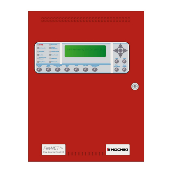
2.3 Control Panel Layout 2.3.1 Front Panel Controls and Display Front Panel 8-Line x 40 Indicators character LCD Front Panel Controls Enable Controls Key-switch (Access Level 2) Figure 2.3.1 – Controls and Display FireNET Plus I & O Manual Version 1.073 Page 23... -
Page 24: Enclosure And Panel Layout
2.3.2 Enclosure and Panel Layout Fire More Events General AC Power On Disablement Pre-Alarm General Trouble Power Trouble On Test Panel Sounder Supervisory Silenced Delay Active NAC Trouble Main Control Unit SLC Loop Battery Connection AC Power Connection Programmable Relays ... -
Page 25: Mounting The Control Panel
2.4 Mounting the Control Panel Consult the environmental specifications listed in Section 2.2 to determine a suitable location to mount the FireNET Plus main control panel. The panel should be mounted so that it is accessible to service personnel and located in a secure area. -
Page 26: Suggested Routing Of Ac Power
2.5.1 Suggested Routing of AC Power Route the AC input power wiring as outlined below. Follow recommendations outlined in section 2.5 regarding the separation of high and low voltage wiring. Fire More Events General AC Power On Disablement General Trouble Pre-Alarm On Test Power Trouble... -
Page 27: Battery Calculations
2.6 Battery Calculations FireNET Plus I & O Manual Version 1.073 Page 27... - Page 28 FireNET Plus I & O Manual Version 1.073 Page 28...
-
Page 29: Electrical Ratings
2.7 Electrical Ratings Rating Terminal Label Description Voltage Current Ground Ground Connection 0VDC 0VDC Ground Ground Connection 48VDC 30mA Incoming phone line connection from telephone company (FNP-1127D/DE only) 48VDC 30mA Phone Line 48VDC 30mA Outgoing phone line connection to telephone sets (FNP-1127D/DE only) 48VDC 30mA... - Page 30 + Battery +24 VDC - Battery DC Common Table 2.7.2 Power Supply Terminal Strip Electrical Ratings NOTE: Earth ground fault detection impedance is approximately 100K ohms between earth ground and the FireNET Plus internal floating DC supply. FireNET Plus I & O Manual Version 1.073 Page 30...
-
Page 31: Specifications
2.8 Specifications Primary AC: 120VAC @ 2.1 amps 50/60hz (or) 240VAC @ 1.1 amp 50/60hz Output DC: 24VDC @ 4 amps Power Supply: 5.25 amp integrated Max Charger Current: 1.25 amps Dimensions: 14.5”W x 19” H x 3.5”D Weight: 20 lbs (without batteries) Color: Red (optional charcoal) Material:... -
Page 32: Section 3 - Power Supply And Main Control Unit Connections
3.2 Battery Connection The FireNET Plus fire alarm control panel can charge up to 60AH batteries maximum. Use the current draw and battery calculation worksheet in section 2.6 to determine the correct battery size to use. - Page 33 Figure 3.1 Power Supply Connection Detail FireNET Plus I & O Manual Version 1.073 Page 33...
-
Page 34: Auxiliary Power Connection
3.3 Auxiliary Power Connection 24 VDC auxiliary powers are available on the main control board for powering remote annunciators, I/O modules and other low-current powered devices. The total output from each Auxiliary Power output must not exceed .360 amps. All devices powered from the auxiliary power terminals should be entered into Table 2.6 and taken into consideration for standby battery size. -
Page 35: Notification Appliance Circuit Connection
3.4 Notification Appliance Circuit Connection NAC outputs rated @ 2.3 amps each (Special Application) ( EOL P/N: S2030 or P/N: S2028 can be used) NAC outputs rated @ 1.6 amps each (Continous) Regulated. (Hochiki America EOL P/N: P/N: S2030 or P/N: S2028 can be used) ... -
Page 36: Relay Output Connection
3.5 Relay Output Connection Relays are dry Form “C” contacts and are fully programmable. See section 8 of this manual for programming. Figure 3.4 Relay Outputs Detail FireNET Plus I & O Manual Version 1.073 Page 36... -
Page 37: Phone Line Connections (Fnp-1127D And Fnp-1127De Only)
FireNET Plus to the same telephone line. NOTE: The maximum distance between the FireNET Plus and the RJ31X jacks must not exceed 6 feet. Do not use a phone cord that is longer than 6 feet in length. -
Page 38: Section 4 - Expander Board Installation
Section 4 – Expander Board Installation 4.1 Compatible Expander Boards The following Hochiki America Corp. expander boards are listed as compatible with the FireNET Plus analog addressable fire alarm system. Expanders FNP-1127-SLC - SLC Loop Expander (Local FACP Expander) ... -
Page 39: Addressing
4.2.2 Addressing Up to 32 RS485 bus devices can be added to the system. Each RS485 bus device must be set to a unique address 1-32. The address for each RS485 bus device is set using a position DIP-switch in binary fashion. Switches 1-5 represent the values 1, 2, 4, 8, 16, and 32 respectively. -
Page 40: Power Connections
4.2.4 Power Connections All RS485 bus devices require 24 VDC to operate. The AUX 24V terminals of the FireNET plus may supply this voltage (360 milliamps maximum), or you may use an external power supply that provides 24 VDC output. Connections are provided on each RS485 bus device for both incoming and outgoing power. -
Page 41: Fn-4127-Io - Input / Output Board
4.3 FN-4127-IO - Input / Output Board In addition to the basic 254 points that the FireNET Plus can accommodate on the SLC loops, additional input and output points can be added by using FN-4127-IO Input/Output boards on the RS485 bus. -
Page 42: Configuring Outputs
FireNET panel. See Section 3.4, Appendix A, and B for details on NAC circuits and compatible NAC devices. When powering the I/O board from the FireNET Plus auxiliary 24VDC power (limited to 360ma), the following maximum wiring distances apply at the gauges noted:... -
Page 43: Led Indicators
4.3.3 LED Indicators LED indicators on the I/O board give some simple diagnostic information and show that the boards are communicating with the control panel. The red LED (LED1) is on during receipt of a message from the control panel. ... -
Page 44: Reserved For Future Use
4.5 Reserved for Future Use FireNET Plus I & O Manual Version 1.073 Page 44... -
Page 45: Fnp-1127-Slc - Slc Loop Expander
4.6 FNP-1127-SLC – SLC Loop Expander The FireNET Plus control panel is provided with one SLC Loop; however an additional SLC Loop may be added at the factory or a later date if required through the use of a FNP-1127- SLC expander board. -
Page 46: Fn-Lcd-S Serial Liquid Crystal Display Annunciator
4.7 FN-LCD-S Serial Liquid Crystal Display Annunciator The FN-LCD-S Serial LCD Annunciator duplicates the indications of the FireNET Plus fire alarm control panel. The FN-LCD-S connects to the control panel via the RS485 serial bus that is designated “COMMS” on the control board. Up to 15 FN-LCD-S annunciators may be connected via the COMMS bus to a single FireNET Plus control panel. - Page 47 FN-LCD- ( - ) S or COMMS other ( + ) RS485 RS-485 ( - ) Device FireNET Plus Control Panel (section) To AUX 24VDC of control panel or to UL 864/1481 listed AUX 24VDC Power Supply FireNET Plus I & O Manual Version 1.073 Page 47...
- Page 48 FN-LCD-S and/or the control panel Aux 24VDC output. The current limits during both standby and in alarm shall not exceed the 360mA rating of the FireNET Plus Aux 24VDC output or the 500mA rating of the FN-LCD-S. The FN-LCD-S current draw is rated as follows:...
-
Page 49: Section 5 - Slc Device Installation
Section 5 – SLC Device Installation 5.1 Compatible SLC Devices The following Hochiki America Corp. SLC devices are listed as compatible with the FireNET Plus analog addressable fire alarm system. Detectors (Sensors) ALK-V / ALK-V2 Analog Photoelectric Smoke Detector ... -
Page 50: Number Of Devices
5.2 Number of Devices The FireNET Plus comes with 1 SLC loop built-in to the panel. The loop can support up to 127 analog addressable detectors and modules as well as 127 analog sounder bases for a total of 254 possible per loop. -
Page 51: Slc Loop Wiring
5.3 SLC Loop Wiring The FireNET Plus uses the patented Hochiki DCP Digital Communication Protocol to communicate with each of the analog addressable devices located on the SLC loops. This extremely fast and reliable protocol allows the use of standard non-twisted, non-shielded wiring for the SLC loops. -
Page 52: Class B Slc Loop Wiring Distance
5.3.1 Class B SLC Loop Wiring Distance Refer to Figure 5.3.1 to determine the maximum length of wire that may be used on a Class B signaling line circuit (SLC). The total wire length of all branches (T-taps) on the SLC loop must not exceed 5,000 feet (per loop) using #14 AWG (see Figure 5.3.2). - Page 53 Class B SLC Loop (with T-taps) 0 Ohm Jumpers (p/n# 0400-01025) Wire Guage Maximum Length of Wire 18 AWG 1,950 Feet 16 AWG 3,100 Feet 14 AWG 5,000 Feet NC C NO NC C NO NC C NO LOOP 1 LOOP 2 LOOP 3 LOOP 4...
-
Page 54: Class A Slc Loop Wiring Distance
5.3.2 Class A SLC Loop Wiring Distance Refer to Figure 5.3.3 to determine the maximum length of wire that may be used on a Class A signaling line circuit (SLC) . Figure 5.3.3 Maximum Wiring Distance for a Class A SLC The SLC wiring must always meet the following requirements (per circuit): ... - Page 55 Additional Notes Regarding Class A SLC loops: No t-taps are allowed on a Class A / Class X SLC loop. The return side of the loop must be routed separately from the outgoing loop. The return side may not share the same conduit or cable as the outgoing side of the SLC loop.
-
Page 56: Addressing Devices
5.4 Addressing Devices Prior to installation, all of the addressable devices installed on the FireNET Plus SLC loop must be programmed with a unique address ranging from 1 to 127. The analog sounder bases will automatically derive their address from the host sensor (detector) attached to them. - Page 57 Figure 5.4 Hochiki TCH-B100-NS Programmer Connections 1. The ASB (ASBL) automatically derives its address from the host sensor (N + 127). 2. Devices must not be powered when using the TCH-B100-NS programmer to set addresses. 3. Mini-modules such as the FRCME-S and FRCME-P should not be connected to the SLC loop when using the TCH-B100-NS programmer to set addresses.
-
Page 58: Detector Addressing
5.4.1 Detector Addressing This section applies to the following Hochiki analog detectors – ALK-V, ALK-V2, ALG-V, ALN-V, AIE-EA, DH-98-A(R), DH-99-A(R), ATG-EA, ATJ-EA, ACA-V, ACB-EA and ACC-V. Follow these steps to program a new address into any one of these analog detectors. (Refer to Figure 5-4) 1. -
Page 59: Mini Module Addressing
5.4.3 Mini Module Addressing This section applies to the Hochiki FRCME-S and FRCME-P addressable mini-module. Follow these steps to program a new address into any of these addressable modules. (Refer to Figure 5-4) 1. Using the programming plug with alligator clips, plug the end with the jack on it into the programming jack on the programmer. -
Page 60: Smoke And Heat Detector Wiring
5.5 Smoke and Heat Detector Wiring This section includes wiring instructions for connecting the following analog detectors to the FireNET Plus fire alarm control panel: ALK-V / ALK-V2, ALN-V Photoelectric Smoke Detector, ALG-V Photoelectric Smoke Detector, AIE-EA Ionization Smoke Detector, ATG- EA, ATJ-EA Heat Detector, ACA-V, ACC-V Multi Detector, ACB-EA / EAW Fixed and Rate of Rise Multi Heat Detector. -
Page 61: Analog Duct Detector Wiring
5.6 Analog Duct Detector Wiring This section includes wiring instructions for connecting the DH98-A, DH99-A analog duct detector, and the DH98-AR and DH99-AR analog duct detector with relay, to the FireNET Plus control panel SLC loop. For detailed instructions on the physical mounting and wiring of FireNET analog duct detectors please refer to the installation instructions that are included with each device. -
Page 62: Dh98-A Analog Duct Detector
Figure 5.6.1 DH98-A Analog Duct Detector 5.6.1 DH98-A Analog Duct Detector Connect the DH98-A analog duct detector to the FireNET Plus control panel SLC loop as shown in Figure 5.6.1. Terminals 3 and 4 can be used to power a remote alarm LED. The ratings on these terminals are 24 VDC at .008 amps maximum. -
Page 63: Dh98-Ar Analog Duct Detector With Relay
In addition to the SLC loop connections, the DH98-AR requires 24-volt reset-able auxiliary power (10mA standby and 55mA alarm) connected to terminals 3+ and 4-. This power may come from the FireNET Plus main control panel auxiliary power (360 mA max.) or from an external power supply. -
Page 64: Frcme-4 Input Module Wiring
Please refer to section 5.4 of this manual for instructions on programming an address into the FRCME-4 input module. Connect the FRCME-4 to the FireNET Plus as shown in figure 5.7.1. Refer to the installation instructions included with the FRCME-4 for more detailed installation and wiring instructions. -
Page 65: Frcme-M Mini Input Module (W/ Terminal Blocks)
The FRCME-M input module is used to connect standard normally open dry contact types of fire alarm devices such as manual pull stations to the FireNET Plus SLC loop. The FRCME-M must be programmed with a unique address from 1-127. All of the dry contact type devices connected to a single FRCME-M appear at the main control panel as a single address. -
Page 66: Frcma / Frcma-I Input Module
The FRCMA / FRCMA-I input module is used to connect standard normally open dry contact types of fire alarm devices such as manual pull stations to the FireNET Plus SLC loop. The FRCMA module provides one class A or one class B input circuit. The FRCMA-I includes built-in short circuit isolation for the SLC loop. -
Page 67: Note: For Sections 5.7, 5.8, And 5.9 Common For All Frcm Devices
NOTE: For Sections 5.7, 5.8, and 5.9 common for all FRCM devices Reference the input wiring distance limitation table below for all types of FRCM modules: Maximum Distance Between Module and EOL Device 14 AWG 1500 Ft. 16 AWG 900 Ft. 18 AWG 550 Ft. -
Page 68: R2M Dual Relay Module Wiring
5.10 R2M Dual Relay Module Wiring The R2M modules provide two separately programmable relay outputs on the FireNET Plus SLC loop. These outputs may be used for a variety of purposes including door holders, elevator recall, and other fire safety functions. -
Page 69: Som Supervised Output Module
The supervised voltage output of the SOM is rated at 2.0A maximum. Connect the SOM to the FireNET Plus control panel as shown in Figure 5.11.1. Refer to the installation instructions included with the SOM for more detailed wiring and installation instructions. -
Page 70: Som-A / Som-Ai Supervised Class A Output Module
SOM-A / SOM-AI is rated at 2.0A maximum. Connect the SOM-AI to the FireNET Plus control panel as shown in Figure 5.12.1. Note that the SLC connections for the SOM-A are like the SOM; there is only one S+ and one SC- terminal. - Page 71 Note regarding the use of Sync Modules with the SOM-A and SOM-AI: The DCP-SOM- A and DCP-SOM-AI modules are suitable for use with Amseco/Potter, Wheelock and Gentex notification appliances in both a Class A and Class B configuration with the appropriate manufacturer’s sync module employed.
-
Page 72: Som-R Supervised Output Module (Preaction Sprinkler Systems)
2. The SOM-R must be addressed using the TCH-B100 programmer. Connect the SOM-R to the FireNET Plus SLC as shown in Figure 5.13.1. Refer to the installation instructions (Part # 1700-11320, Rev. 05/10) included with the SOM-R for additional wiring and installation instructions. - Page 73 5. Connect the output of the SOM-R to the input terminals on the SOM-R-DS keyswitch connected to the FRCME module. Ensure correct polarity. 24 VDC Power provided by: 1) UL 1481 listed, regulated, power limited supply for fire alarm signaling service 2) Auxiliary Power (X2 terminals 18 SOM-R...
- Page 74 Important! For proper operation, program the SOM-R Output Attributes as follows: o Gen Alarm Mode = YES o Silenceable = NO o Emergency = NO o Pre Alarm = NO o Trouble = NO o Pattern = CONTINUOUS o Edit Location Text = SOMR Program the FRCME attributes as follows: o Set Input Type = GEN PURPOSE N/C EOL o Set Input Action = SUPERVISORY...
- Page 75 Maintenance: A maintenance agreement should be arranged through the local manufacturer’s representative and maintenance should be performed annually by authorized personnel only. To keep a preaction system in excellent working order, ongoing maintenance is required per the manufacturer’s recommendations and UL and NFPA standards.
-
Page 76: Czm Conventional Zone Module
5.14 CZM Conventional Zone Module The Conventional Zone Module (CZM) connects to the Signal Line Circuit (SLC). The module allows the analog panel to interface with and monitor conventional devices such as pull stations and two-wire smoke detectors. The CZM is typically used in retrofit situations where pre-existing conventional zones are removed from a conventional system and then connected to the analog panel for discrete monitoring of that zone. -
Page 77: Dimm Dual Input Monitor Module
5.15 DIMM Dual Input Monitor Module The Hochiki DIMM Dual Input Monitor Module is designed to work with pull stations, water flow switches, and other applications requiring the monitoring of dry contact alarm initiating devices. The DIMM can monitor two independent inputs with discrete reporting, yet the module only requires a single address on the SLC Loop. -
Page 78: Sci Short Circuit Isolator Module
Section 5.16.1), no devices are lost from a single short on the SLC loop. Connect the SCI module to the FireNET Plus control panel as shown in Figure 5.16.1. Refer to the installation instructions included with each SCI for more detailed wiring and installation instructions. -
Page 79: Class A Operation
5.16.1 Class A Operation The SCI should be located within 5 feet of the FireNET Plus control panel on both the outgoing and incoming SLC loop legs. In addition an SCI should be located between every SLC loop detector and module as shown in figure 5.15.2 and is required for NFPA 72 Class A Style 7 compliance. -
Page 80: Class B Operation
5.16.2 Class B Operation The SCI modules may be strategically located based on the installer or designer’s discretion. Typically they are located at the beginning of each branch of the SLC loop as indicated in figure 5.15.3. In the event of a short circuit on the SLC loop, the closest SCI to the short circuit will activate and it’s LED will turn on. -
Page 81: Asb & Asbl Analog Sounder Base
5.17 ASB & ASBL Analog Sounder Base The Analog Sounder Base (ASB & ASBL) connects to the SLC Loop and requires 24VDC aux power to operate. The ASB (ASBL) contains an addressable sounder that is controlled by the control panel. The ASB derives its address from the Host detector (ALK, ALN, ALG, AIE, ATG, ATJ, ACA, ACB, ACC) upon power up. -
Page 82: Ams Addressable Manual Pull-Station
AMS device. Connect the AMS to the FireNET Plus control panel as shown in Figure 5.17.1. Refer to the installation instructions included with the AMS device for more detailed installation and wiring instructions. -
Page 83: Section 6 - Network Connections
Please refer to Section 8 of this manual for more information on programming the FireNET Plus control panel. The FireNET system enables information to be transmitted between control panels using a secure network connection. -
Page 84: Fn-4127-Nic Network Interface Card
To enable control panels to be connected together as a network, a network card must be installed in FN-4127-NIC each panel. This card connects to the FireNET Plus Network Card on the rear of the main control board and is held in M3 Screws position by two M3 screws. - Page 85 4000 ft. (1200m) and because the data is re-transmitted at each network card, in theory, there can be 4000 ft. (1200m) between each card if required. The minimum cable size for the FireNET Plus network is #20 AWG. The network communications uses RS485 technology.
- Page 86 4 LOOP 2000 Feet 2000 Feet When designing or installing a network of FireNET Plus panels, always be aware of the following: 1. The panel network must be wired as a ring (Class A). 2. There should be no more than 4000 ft. (1200m) maximum cable length between two adjacent segments.
- Page 87 6.1.1.5 Connecting the network cable All panels will have two cables connected to another panel or panels. If either of these is not connected a trouble condition will be displayed. The connection is polarity sensitive. The + and – from one panel must connect to the + and – of the next panel and so on. The temperature of the cable should not exceed 131 degrees F (55 C).
-
Page 88: Section 7 - Basic Front Panel Operations And Programming
Section 7 - Basic Front Panel Operations and Programming (Access Level 1, 2, and Real-Time Operation) This section covers the basic user operations of the FireNET Plus and is intended to provide the casual user a basic understanding of how to complete common system operations. -
Page 89: Operating Modes
Section 8 of this manual. 7.1.1 Access Level 1 When the FireNET Plus control panel is in Normal Standby condition only the green AC Power On LED will be lit, and the date and time displayed on the LCD display. Normal Standby is considered to be in Access Level 1. -
Page 90: Access Level 1 Operations
7.2.4 Menu Navigation (Up, Down, Left, Right Arrows, Enter / Exit Buttons) These buttons are used to navigate the FireNET Plus menu structure. The arrow buttons (up, right, down, left) also represent the digits 1, 2, 3, and 4 respectively when entering codes for Access Level 2 or Access Level 3 modes. -
Page 91: Access Level 2 Operations
Access Level 2. NOTE: The FireNET Plus panel will NOT time out to Level 1 when using the key. Be sure to return the key to the OFF position and remove it when not in use! 7.3.2 Silencing an Alarm... -
Page 92: Resetting An Alarm
7.3.5 Initiating a Fire Drill To initiate a fire drill, place the FireNET Plus panel into Access Level 2 operating mode as described in 7.3.1. Press the “Fire Drill” button to engage fire drill mode. The fire drill activates NAC and SOM indication circuits, but does not activate fire relays, R2M, programmable relays, etc. -
Page 93: Advanced Access Level 2 Operations
The Disablements menu allows the user to disable individual points, circuits, zones, or loops on the FireNET Plus fire alarm system. This is typically done while the system is being serviced or tested or to temporarily remove a faulty system device. CAUTION: Any portion of the system that is disabled will not report an alarm condition. - Page 94 Note: The FireNET Plus fire alarm system will indicate a disabled condition any time there is an active disablement on the system, via LCD display text and the “point bypassed” LED on the front panel.
-
Page 95: View Devices
Test.” 7.4.5 Set System Time This sub-menu option is used to adjust the FireNET Plus internal clock. It is important to make sure the clock is accurate so that events logged in the event log are recorded with the correct time. - Page 96 each option by using the up/down arrow keys. Press the right arrow key to select it. Use the up/down arrow keys to change the current values. Pressing the left arrow key in any menu backs you out to the previous menu. 7.4.6 Sensor Maintenance Early Warning This option is used by service personnel to identify sensors that require cleaning or replacement.
-
Page 97: Panel Operation
This section summarizes the operations described earlier in this section of the manual for handling Fire, Trouble, and Supervisory conditions. 7.5.1 Fire Condition In the event a device on the FireNET Plus fire alarm system activates in a fire alarm condition the following will happen: ... -
Page 98: Trouble Condition
A supervisory condition is detected when a portion of a building system that controls the spread of fire or smoke is disabled. This is most commonly a fire sprinkler valve that is turned off for maintenance purposes. When the FireNET Plus fire alarm control panel senses a supervisory condition the following will occur: FireNET Plus I & O Manual Version 1.073... - Page 99 Investigate the cause of the supervisory conditions. If the supervisory condition cannot be resolved, contact your service company. Once the supervisory condition has been cleared, reset the FireNET Plus fire alarm control panel by entering Access Level 2 and pressing the “Reset” button.
- Page 100 If the Pre-Alarm condition cannot be resolved, contact your service company. Once the Pre-Alarm condition has been cleared, reset the FireNET Plus fire alarm control panel by entering access level 2 and pressing the “reset” button.
-
Page 101: Dact Operation And Event Reporting Codes (Fnp-1127D Only)
Contact ID and SIA formats 7.62 Phone Line and Phone Number Selection The FireNET Plus DACT can be configured with up to four account numbers and four phone numbers. Each phone number corresponds to an account (phone number 1 is used with Account 1;... -
Page 102: Phone Line Supervision
Investigate and correct the cause of this condition immediately. 7.6.3 Phone Line Supervision The FireNET Plus supervises both telephone lines for the presence of normal line voltage. Each line is checked every 10 seconds. If trouble with a phone line is detected, the FireNET display will indicate the trouble condition. -
Page 103: Report Groups
7.6.4 Report Groups The FireNET Plus has five report groups that can be selected to maximize the reporting options. Each group includes specific types of events that will be reported. The report groups are selected by account, with account 2 and 4 also having a selection for backup reporting. -
Page 104: Communication Failure
7.6.5 Communication Failure If all attempts to communicate to an account fail, the FireNET Plus will display a “Comms Fail” trouble condition, along with the number of the account that failed (1 – 4). The original event will be removed from the report queue. If there are additional events to be reported the panel will attempt to report them, along with a communication failure event. - Page 105 As with Contact ID, the Zone or Address option is programmable. Panel address information is not reported in SIA format. The following Table shows the event codes for the FireNET Plus communicator, with a brief explanation of what may cause each event.
- Page 106 Panel Reboot FT / FJ Reset Button on Display Board Pressed Panel Reset Button OR / OR Reset Button on Panel Pressed Phone Line 1 Trouble LT / LR Trouble on Dialer Phone Line # 1 Phone Line 2 Trouble LT / LR Trouble on Dialer Phone Line #2 SLC Open Circuit...
- Page 107 Note #1 – This event can also be generated by Panel and I/O Module Inputs. Note #2 – Zone information is not reported for this event. Note #3 – In SIA format, the following events use the same code for the activation and restore: Alarm Silence (FL / FL) and Panel Reset (OR / OR).
-
Page 108: Section 8 - Advanced Front Panel Operations And Programming (Access Level 3)
(Access Level 3) 8.1 Access Level Overview The FireNET Plus has 3 modes of operation. Access Levels 1 and 2 are operational levels that allow the user to perform operational commands such as silencing an alarm or resetting the panel. Access Levels 1 and 2 are explained in further detail in Section 7 - Basic Front Panel Operation and Programming. -
Page 109: Access Level 3 Menu
Note: If you back out of the Access Level 3 menu using the Exit button or the left arrow key, you will have to re-enter the code to go back into Access Level 3 operating mode. 8.2 Access Level 3 Menu Figure 8.2 shows the menu structure of the Access Level 3 main menu. - Page 110 Help (?) button for additional information. 8.2.1.3 Edit I/O The EDIT I/O menu option allows the user to set the attributes of all the FireNET Plus control panel input and output circuits. Selecting EDIT I/O displays a sub-menu giving the user the choice of “Edit Panel I/O”...
- Page 111 o Input action is the type of event that occurs when the input is activated. Choose between Trouble, Pre-Alarm, Supervisory, Auxiliary, Silence Alarm, Reset, Transparent, Disablement, Test, or Fire. Edit Location Text o This option allows the user to scroll through the available characters using the arrow keys, and create a custom text message up to 40 characters describing the input.
- Page 112 o When outputs are assigned to zones, the output operation can be triggered on a zoned basis. General alarm mode should be set to “zonal” for this operation. Programmable o When outputs are not assigned to general event categories via output attributes, the output operation is programmable by using Cause and Effect.
- Page 113 8.2.1.3.3 Add / Edit Dialer This option allows the integrated dialer (DACT) to be enabled and programmed. Enabling the DACT: To enable the DACT, select “Add Dialer” from the Edit I/O menu and press the Enter button. Programming the DACT: From the Edit I/O menu select “Edit Dialer”. You will see the following display.
- Page 114 If the phone number field is left empty for an account (no phone number programmed), the FireNET Plus will not use that account. Note: To comply with UL and NFPA standards, the FireNET Plus must be programmed for backup reporting. To accomplish this, program an account number and phone number for accounts 1 and 2.
- Page 115 Use the up or down arrow key to select the test report time. The test report will be sent every 24 hours at the time selected. Press the Enter button when the desired time is displayed. 8.2.1.3.3.3 Set Remote Configuration This option enables the panel to accept a programming download from a remote computer.
- Page 116 8.2.1.5 Edit Device Attributes Selecting EDIT DEVICE ATTRIBUTES from the EDIT CONFIGURATION MENU allows the user to set attributes specific to each SLC loop device on the system. After selecting the SLC loop where the device is located, the user can scroll through each SLC device on that loop and set attributes specific to that device.
- Page 117 General Alarm mode (Common Fire Alarm): This option allows a user to enable or disable the global General Alarm mode for a selected output(s). When enabled, the output follows the panels General Alarm mode (see 8.2.1.2). When disabled, the output will not follow the General Alarm mode, allowing control by cause and effect logic statements.
- Page 118 8.2.1.6 Auto Learn Auto Learn is a utility that can be run to quickly identify and enroll all of the SLC loop devices on the FireNET Plus control panel as well as the panel’s internal structure and default network routing and nodes.
- Page 119 The SET TIMES menu option allows the installer to set the smoke detector calibration time, the day / night sensitivity times, and the Sounder Time-Out for the panel. 8.2.2.1 Calibration Time This menu option sets the time of day that the panel will perform calibration on the system smoke detectors.
-
Page 120: Print Configuration
event log. The event log is a very useful tool for troubleshooting system problems or verifying that certain activities, such as Fire Drills, actually took place. The View Print Event Log menu option is covered in greater detail in the Testing and Troubleshooting section of this manual. -
Page 121: Loop Data Test
NOTE: The following values must be set to be compliant with UL864 9 Edition. See prefix of this manual for additional details. Buzzer – Enabled Ground Trouble – Enabled Buzzer Access Level – 2 8.2.6 Loop Data Test ACCESS LEVEL 3 MENU EDIT CONFIGURATION SET TIMES... -
Page 122: Section 9 - Testing And Troubleshooting
Section 9 - Testing and Troubleshooting 9.1 One Man Walk Test - TEST ZONES The one-man walk test feature is intended to allow a single service person the ability to test each device without having to reset the panel each time a device is activated. While in test mode, the panel will automatically reset after 3 seconds following any device activation. -
Page 123: View / Print Event Log
NOTE The FireNET Plus panel will be placed in a trouble condition during test mode. The “ON TEST” LED will also illuminate. 9.2 View / Print Event Log The View Print Event Log menu command allows the user to view the systems 500-event memory log. -
Page 124: Print Event Log
You may view individual events by using the up and down arrow keys: VIEW TROUBLE EVENTS 120/120 * TROUBLE:SOM ZONE 02 * ADR=012.00 LOOP=1 ND=1 AUTOLEARN TIME 14:35 05/08/2003 Disconnected trouble Cleared Use UP/DOWN arrow keys to scroll events 9.2.2 Print Event Log To print the event log, you must enter Access Level 3 as noted above. -
Page 125: Clear Event Log
9.2.3 Clear Event Log To clear the event log, you must enter Access Level 3 as noted above. Once in Access Level 3, select VIEW PRINT EVENT LOG. Then select the “Clear Event Log”. VIEW EVENT LOG MENU View Event Log ►... -
Page 126: Loop Data Test
When the time does come at that problem job site, the Loop Data Test Function can be easily activated to monitor communication between the FireNET Plus and loop devices. This tool displays the time and date of the test activation, the number of successful and unsuccessful communication packets on the loop, and the current date and time. - Page 127 Then select “START TEST”. LOOP DATA TEST ► START TEST The Loop Data Test result will then display in real time on the screen. LOOP DATA TEST (LOOP: 2) Start Date : 9/05/2007 12:28:00 Good Readings: 0017824 Bad Readings: 0000000 Current Date: 9/05/2007 13:06:01 Press the Exit button when the Loop Data Test is completed.
-
Page 128: Troubleshooting
9.4 Troubleshooting This section is currently being developed from data collected from installation sites and technical support inquiries. The following is an example (in FAQ format) of the information being developed: Q – I need to change an ALG-V smoke sensor to an ATG-EA heat sensor. Do I have to auto-learn the loops again? A –... -
Page 129: Trouble Conditions
9.5 Trouble Conditions Network Troubles: 9.5.1 Network open or short circuit trouble This is quite self explanatory and indicates a cabling trouble between two nodes. However, by observing the green and red LEDs on the network card it is possible to see whether the trouble is on the incoming or outgoing network circuit. - Page 130 9.5.7 Network comms trouble Highly sophisticated error checking and filtering is used in the FireNET Plus network protocol. It is possible under extreme conditions for data packets to become corrupted and not be received by a panel. In these circumstances this trouble message will be displayed.
-
Page 131: Section 10 - Installation Records
Use the example below to complete the information in Table 10.3 for the Network devices installed on the system. Node Device Description Location (1-64) Control Panel FireNET Plus FACP for the main building South wall of the main entry lobby Control Panel FireNET Plus FACP for Warehouse Warehouse FireNET Plus I & O Manual Version 1.073 Page 131... - Page 132 Table 10.1 FireNET Plus SLC Loop Point Record Loop Address Zone Loop Address Zone Description Description (1-2) (Sub) (1-500) (1-2) (Sub) (1-500) FireNET Plus I & O Manual Version 1.073 Page 132...
- Page 133 Loop Address Zone Loop Address Zone Description Description (1-2) (Sub) (1-500) (1-2) (Sub) (1-500) FireNET Plus I & O Manual Version 1.073 Page 133...
- Page 134 Loop Address Zone Loop Address Zone Description Description (1-2) (Sub) (1-500) (1-2) (Sub) (1-500) FireNET Plus I & O Manual Version 1.073 Page 134...
- Page 135 Loop Address Zone Loop Address Zone Description Description (1-2) (Sub) (1-500) (1-2) (Sub) (1-500) FireNET Plus I & O Manual Version 1.073 Page 135...
- Page 136 Loop Address Zone Loop Address Zone Description Description (1-2) (Sub) (1-500) (1-2) (Sub) (1-500) FireNET Plus I & O Manual Version 1.073 Page 136...
- Page 137 Loop Address Zone Loop Address Zone Description Description (1-2) (Sub) (1-500) (1-2) (Sub) (1-500) FireNET Plus I & O Manual Version 1.073 Page 137...
- Page 138 Loop Address Zone Loop Address Zone Description Description (1-2) (Sub) (1-500) (1-2) (Sub) (1-500) FireNET Plus I & O Manual Version 1.073 Page 138...
- Page 139 Loop Address Zone Loop Address Zone Description Description (1-2) (Sub) (1-500) (1-2) (Sub) (1-500) FireNET Plus I & O Manual Version 1.073 Page 139...
- Page 140 Loop Address Zone Loop Address Zone Description Description (1-2) (Sub) (1-500) (1-2) (Sub) (1-500) FireNET Plus I & O Manual Version 1.073 Page 140...
- Page 141 Table 10.2 RS485 Bus Device Record Address Device Description Location (1-32) FireNET Plus I & O Manual Version 1.073 Page 141...
- Page 142 Table 10.3 Network Node Device Record Node Device Description Location (1-64) FireNET Plus I & O Manual Version 1.073 Page 142...
- Page 143 Node Device Description Location (1-64) These tables may be photocopied if additional pages are necessary. FireNET Plus I & O Manual Version 1.073 Page 143...
-
Page 144: Appendix A - Compatible Devices
Appendix A - Compatible Devices A.1 Two-Wire Smoke Detectors Table A.1 lists the 2-wire smoke detectors that are compatible with the CZM conventional zone module. Table A.1: Compatible 2-Wire Smoke Detectors with the Hochiki FireNET CZM Module Compatibility ID Number of Manufacturer Model Number Detectors per... -
Page 145: Compatible Notification Appliances
A.3 Compatible Notification Appliances All notification appliance devices determined to be compatible with the synchronization modules shown below are compatible for operation with the FireNET Plus fire alarm control panel under Regulated (Continuous) operation: Manufacturer Manufacturer Sync Module Maximum NAC Load... -
Page 146: Gentex Compatible Nac Devices
A.3.1 Gentex Compatible NAC Devices The following devices from Gentex are recommended for use with the FireNET Plus control panel for synchronized applications on NAC 1 and NAC 2: Gentex Environment Model Series Description Mount WSSPK Series Outdoor WSSPK24-15/75 Speaker Strobe... - Page 147 Speaker/Strobe Round Indoor SSC-2 Speaker Strobe Wall/Ceiling Speaker/Strobe round Indoor SSC-8 Speaker Strobe Wall/Ceiling Select-A-Strobe Indoor SL-1224 Strobe Wall Select-A-Strobe Indoor/Outdoor SL-1224-WP Strobe Wall Select-A-Strobe Indoor SL24C-3075110 Strobe Wall/Ceiling Select-A-Strobe Indoor SL24C-177 Strobe Wall/Ceiling Bell/Select-A-Strobe Indoor SB24 Bell Strobe Wall/Ceiling Select-A-Strobe/Chime Indoor SCM24W-153075...
-
Page 148: Wheelock Compatible Nac Devices
A.3.3 Wheelock Compatible NAC Devices The following devices from Wheelock are recommended for use with the FireNET Plus control panel for synchronized applications on NAC 1 and NAC 2: Wheelock Description Mount AMT-12/24 Mutilating – 3 Input AMT-241575, AMT-24MCW Mutilating Strobe – 1575cd or 15, 30. 75, 110cd... - Page 149 ET70-24MCWH Speaker Strobe – 135, 185cd Wall ET90-24MCCH Speaker Strobe – 115, 177cd Ceiling ET80-24MCW Speaker Strobe – Vandal Resist. 15, 30, 75, 110cd Wall ET80-24MCWH Speaker Strobe – Vandal Resist. 135, 185cd Wall ET70WP-2475 Speaker Strobe Wall HS-24 Audible HS4-241575 Audible Strobe –...
-
Page 150: System Sensor Compatible Nac Devices
A.3.4 System Sensor Compatible NAC Devices The following devices from System Sensor are recommended for use with the FireNET Plus control panel for synchronized applications on NAC 1 and NAC 2: System Sensor Environment Model Series Description Mount SpectrAlert Advance... -
Page 151: Compatible 24Vdc Devices
2.6 of this manual. Table A.4 lists 24VDC devices that are compatible with the FireNET Plus fire alarm control panel Regulated outputs, though specific compatibility is not required when outputs are rated as Regulated by UL. -
Page 152: Changing The Power Supply To 240Vac Operation
240VAC, follow the steps below: 1) Be sure that the FireNET Plus is NOT powered during this procedure! 2) Open the display panel to expose the back side of the FireNET Plus circuit board. 3) In the middle of the circuit board you will see a jumper labeled J1. - Page 153 SLC branch circuit cable requirments or 0400-01046 Total wire must not exceed 5,000 feet from the NOTE: FireNET Plus employs an option for Sounder Time- control panel when using #14 AWG Out (for NAC/SOM/ASB), which can be programmed in 5 min.
-
Page 154: Appendix C - Warranty
Appendix C - WARRANTY Hochiki America Corporation manufactured equipment is guaranteed to be free from defects in materials and workmanship for a period of one (3) year from date of original shipment. HOCHIKI will repair or replace, at its option, any equipment which it determines to contain defective material or workmanship.
Need help?
Do you have a question about the FireNET Plus and is the answer not in the manual?
Questions and answers