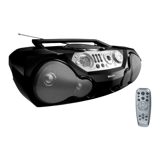
Philips AZ 2048 Service Manual
Cd sound machine
Hide thumbs
Also See for AZ 2048:
- Manual (14 pages) ,
- Specifications (2 pages) ,
- Specification sheet (2 pages)
Table of Contents
Advertisement
CD Sound Machine
TABLE OF CONTENTS
Technical Specification & Service tools...........................2 - 1
Service Measurement......................................................2 - 2
Connections and controls.......................................3 - 1..3 - 2
Instructions for use .................................................3 - 3..3 - 5
Disassembly Diagram......................................................4 - 1
CD Service Test program .....................................4 - 2 .. 4 - 3
Block Diagram .................................................................5 - 1
Wiring Diagram ................................................................5 - 2
Circuit diagram ........................................................6 - 1
Front part.................................................................6 - 2
Tuner part................................................................7 - 1
©
Copyright 2001 Philips Consumer Electronics B.V. Eindhoven, The Netherlands
All rights reserved. No part of this publication may be reproduced, stored in a retrieval
system or transmitted, in any form or by any means, electronic, mechanical, photocopying,
or otherwise without the prior permission of Philips.
Published by LX 0226 Service Audio
Printed in The Netherlands
Subject to modification
CD part 2 ................................................................8 - 2
AF part.....................................................................9 - 1
Layout diagram (copper side)................................10 - 1
Layout diagram (component side).........................10 - 2
MP3-CD2002 BAORD
Circuit diagram ......................................................11 - 1
Layout diagram......................................................11 - 2
Exploded view - cabinet.................................................12 - 1
Mechanical partslist .......................................................12 - 1
Electrical partslist .............................................13 - 1 .. 13 - 9
AZ 2048
all versions
CLASS 1
LASER PRODUCT
© 3140 785 32130
Advertisement
Table of Contents

Related Manuals for Philips AZ 2048


Summary of Contents for Philips AZ 2048
-
Page 1: Table Of Contents
LASER PRODUCT © Copyright 2001 Philips Consumer Electronics B.V. Eindhoven, The Netherlands All rights reserved. No part of this publication may be reproduced, stored in a retrieval system or transmitted, in any form or by any means, electronic, mechanical, photocopying, or otherwise without the prior permission of Philips. -
Page 2: Handling Chip Components
1 - 1 HANDLING CHIP COMPONENTS © ñ WARNING WAARSCHUWING All ICs and many other semiconductors are susceptible to Alle IC´s en vele andere halfgeleiders zijn gevoelig voor electrostatic discharges (ESD). Careless handling during electrostatische ontladingen (ESD). repair can reduce life drastically. Onzorgvuldig behandelen tijdens reparatie kan de levensduur When repairing, make sure that you are connected with the drastisch doen vermindern. -
Page 3: Technical Specifications
2 - 1 TECHNICAL SPECIFICATIONS GENERAL TUNER - AM SECTION Tuning range MW : 531 - 1602 kHz Mains voltage -/00 : 230 V LW : 153 - 279 kHz -/01 : 120 / 230 V IF frequency : 450 kHz – 1 kHz Mains freq. -
Page 4: Service Measurement
2 - 2 SERVICE MEASUREMENT Bandpass Tuner SW LF Voltmeter 250Hz-15kHz Aerial replacement e.g. PM2534 e.g. 7122 707 48001 RF Generator Capacitor e.g. PM5326 S/N and distortion meter e.g. Sound Technology ST1700B To avoid atmospheric interference all AM-measurements have to be carried out in a Faraday«s cage. Use a bandpass filter (or at least a high pass filter with 250Hz) to eliminate hum (50Hz, 100Hz). -
Page 5: Connections And Controls
3 - 1 CONNECTIONS AND CONTROLS... - Page 6 3 - 2 CONNECTIONS AND CONTROLS...
-
Page 7: Instructions For Use
3 - 3 INSTRUCTIONS FOR USE... - Page 8 3 - 4 INSTRUCTIONS FOR USE...
-
Page 9: Trouble Shooting
3 -5 TROUBLE SHOOTING If a fault occurs, first check the points listed below before taking the set for repair. Do not open the set as there is a risk of electric shock. If you are unable to remedy a problem by following these hints, consult your dealer or service centre. WARNING: Under no circumstances should you try to repair the set yourself, as this will invalidate the guarantee. - Page 10 3 - 6 TUNER ADJUSTMENT TABLE ( ECO6 FM/MW- and FM/MW/LW - versions with ferrite antenna) Waverange Input frequency Input Tuned to Adjust Output Scope/Voltmeter VARICAP ALIGNMENT 108MHz 5130 8V –0.2V 87.5 - 108MHz 87.5MHz 4.3V –0.5V (65.81 - 74, 87.5 - 108MHz) check (65.81MHz) (1.2V –0.5V)
-
Page 11: Disassembly Diagram
4 - 1 4 - 1 DISASSEMBLY DIAGRAM D. REMOVE DECK MECHANISM - REMOVE SCREWS D6 (2.5X10) 4 PCS. A. REMOVE FRONT CABINET ASSEMBLY - REMOVE CD DECK - REMOVE SCREWS A1 (3X20) 9 PCS. A1 (x9) - REMOVE SCREW A2 (3X10) 1 PC (INSIDE CD DOOR) C. -
Page 12: Cd Service Test Program
4 - 2 4 - 2 SERVICE TEST PROGRAM STOP button pressed in any step returns to begin of Service Testprogram. To leave Service Testprogram press POWER to switch off. Door switch is ignored → CD door can be opened. To enter Service * Volume up/down buttons function independentely Testprogramm hold... - Page 13 4 - 3 4 - 3 Abbreviations and Pin-description of CD ICs Abbreviations and Pin-description of CD ICs SERVO PROCESSOR SAA7325H SERVO PROCESSOR SAA7325H SYMBOL DESCRIPTION SYMBOL DESCRIPTION HFREF comparator common mode input microcontroller interface R/W and load control line input (4-wire bus mode) HFIN comparator signal input SILD...
-
Page 14: Block Diagram
5 - 1 5 - 1 BLOCK DIAGRAM Ripple Filter LCD DISPLAY ECO6 Sound Processor with Source Selector, LAYOUT 3 Bands EQ, DBB and ALC CELL 4.19MHz REMOTE A_on MP3CD2002TXT SENSOR TMP86CH21 LAYOUT Mute CELL Power Mute Speaker EEPROM Amp. Ctrl *Optional CD99 (MP3) -
Page 15: Wiring Diagram
5 - 2 5 - 2 WIRING DIAGRAM CD DOOR SWITCH 1403 9V BATTERY 1403 DIPMATE MECHANISM 8205 OE / OE OE / SMF 8202 HR / OE 8410 8201 OE / PH TRANSFORMER VOLTAGE SELECTOR 1010 110-127V 220-240V BATTERIES BLUE OE / OE ORANGE... -
Page 16: Key Board Circuit Diagram
6 - 1 6 - 1 KEY BOARD - CIRCUIT DIAGRAM 1257 A7 1702 E9 1706 E4 1710 D4 1714 D6 1718 D3 2700 E8 2704 E7 3703 E3 3707 D3 3711 C4 3715 E8 3719 D9 3723 B4 F702 C9 F706 C9 F710 A3 1258 A8... -
Page 17: Combi Board - Circuit Diagram Front Part
6 - 2 6 - 2 COMBI BOARD - CIRCUIT DIAGRAM (FRONT PART) e1 F14 2400 B9 2407 G4 2414 E4 2421 I10 2428 D12 2435 F13 2442 F14 3402 F2 3410 G7 3417 E10 3425 F9 3432 D4 3439 H9 3446 B11 3456 G13 3463 C12... -
Page 18: Tuner Part
7 - 1 7 - 1 COMBI BOARD - CIRCUIT DIAGRAM (TUNER PART) 1105 A2 4104 L7 1121 H20 4105 B12 1122 G20 4109 D5 2101 B5 4110 D5 TUNER BOARD ECO6 /PORTABLE AUDIO 2103 D9 5102 G4 AM-IF1 2104 A4 5103 H3 VERSION PROGRAMMING COMPONETS 5111... -
Page 19: Combi Board - Circuit Diagram Cd Part 1
8 - 1 8 - 1 COMBI BOARD - CIRCUIT DIAGRAM (CD PART 1) 1800 C1 2816 F10 2823 B11 2831 F12 2838 G4 2863 B7 2872 B8 2879 E6 3802 A7 3809 A8 3816 C7 3823 E5 3830 E7 3837 C14 3846 F11 3853 H5... -
Page 20: Cd Part 2
8 - 2 8 - 2 COMBI BOARD - CIRCUIT DIAGRAM (CD PART 2) 1820 C3 2844 A5 2848 C5 2853 E7 3838 D1 3867 A5 3871 A7 3876 B6 3881 E7 3911 C1 7810-B C6 MP807 D10 MP823 D3 MP865 E7 MP871 D10 MP881 D3... -
Page 21: Af Part
9 - 1 9 - 1 COMBI BOARD - CIRCUIT DIAGRAM (AF PART) a1 A13 b3 B14 f2 C2 a19 B13 b11 B14 1251 H3 2251 G4 2262 F14 2323 B14 2501 B5 2512 D6 2532 C7 2556 D3 3258 F8 3269 H10 3280 F15 3291 E14... -
Page 22: Combi Board - Layout Diagram
10 - 1 10 - 1 COMBI BOARD - LAYOUT DIAGRAM (COPPER SIDE) -
Page 23: Layout Diagram (Component Side)
10 - 2 10 - 2 COMBI BOARD - LAYOUT DIAGRAM (COMPONENT SIDE) -
Page 24: Circuit Diagram
11 - 1 11 - 1 CIRCUIT DIAGRAM - MP3CD2002 BOARD MP3-CD-2002 2451 B5 2452 B2 2453 B4 2454 B7 2455 C2 only for FLASH version 2456 C12 2457 D9 2450 3465 2458 C10 2459 D2 100n 100R +3.3V +core +3.3V 2460 E13 +3.3V... - Page 25 11 - 2 11 -2 LAYOUT DIAGRAM - MP3CD2002 BOARD 1460 A3 3449 C3 3460 C2 3482 B2 3492 A3 6450 C2 1451 B5 2457 A2 2469 B4 3469 C4 3479 A2 4450 A4 2456 A4 3452 B2 3461 B5 3483 B2 3493 B2 7450 B4...
-
Page 26: Mechanical Partslist
12 - 1 12 - 1 EXPLODED VIEW DIAGRAM - CABINET (9x) SCREW LIST : M2x6 T2 x 8 T2 x 10 T2.5 x 10 T3 x 8 T3 x 10 1011 (2x) T3 x 12 1006 T3 x 16 T3 x 20 1005 T3 x 32... -
Page 27: Electrical Partslist
13 - 1 ELECTRICAL PARTSLIST - MP3CD2002 BOARD - MISCELLANEOUS - - RESISTORS - 1451 2422 025 17303 FFC Connector 19P 3469 4822 051 30101 100R 5% 0,062W 1460 4822 242 10989 CSTCV16,93MXJ0C 3 3470 4822 117 12971 15R 5% 3471 4822 051 30339 33R 5% 0,062W... - Page 28 13 - 2 ELECTRICAL PARTSLIST - COMBI BOARD - MISCELLANEOUS - - CAPACITORS - 1002 3103 308 66770 PBAS 8 MP3CD2002 2101 4822 126 11785 47pF 5% NP0 50V 1004 2422 264 00448 LOUDSPEAKER 4R 6W 2103 5322 126 11578 1nF 10% X7R 50V 1005 2422 264 00448...
- Page 29 13 - 3 ELECTRICAL PARTSLIST - COMBI BOARD - CAPACITORS - - CAPACITORS - 2192 5322 126 11578 1nF 10% X7R 50V 2416 2238 586 59812 100nF +80-20% Y5V 50V 2193 5322 126 11578 1nF 10% X7R 50V 2418 5322 12611583 10nF 10% X7R 50V 2194 5322 126 11578...
- Page 30 13 - 4 ELECTRICAL PARTSLIST - COMBI BOARD - CAPACITORS - - CAPACITORS - 2533 2238 586 59812 100nF +80-20% Y5V 50V 2848 2020 552 94427 100pF 5% NP0 50V 2534 2238 586 59812 100nF +80-20% Y5V 50V 2849 4822 126 13883 220pF 5% 50V 2535 2238 586 59812...
- Page 31 13 - 5 ELECTRICAL PARTSLIST - COMBI BOARD - RESISTORS - - RESISTORS - 3125 4822 051 30103 10K 5% 0,062W 3269 4822 051 10102 1K 2% 0,25W 3128 4822 051 30222 2,2K 5% 0,062W 3270 4822 051 10102 1K 2% 0,25W 3132 4822 051 30479 47R 5% 0,062W...
- Page 32 13 - 6 ELECTRICAL PARTSLIST - COMBI BOARD - RESISTORS - - RESISTORS - 3713 4822 051 30102 1K 5% 0,062W 3846 4822 051 30472 4,7K 5% 0,062W 3714 4822 051 30222 2,2K 5% 0,062W 3847 4822 117 10834 47K 1% 0,1W 3715 4822 051 30101 100R 5% 0,062W...
- Page 33 13 - 7 ELECTRICAL PARTSLIST - COMBI BOARD - RESISTORS - - RESISTORS - 3713 4822 051 30102 1K 5% 0,062W 3846 4822 051 30472 4,7K 5% 0,062W 3714 4822 051 30222 2,2K 5% 0,062W 3847 4822 117 10834 47K 1% 0,1W 3715 4822 051 30101 100R 5% 0,062W...
- Page 34 13 - 8 ELECTRICAL PARTSLIST - COMBI BOARD - RESISTORS - - RESISTORS - 3905 4822 051 30471 470R 5% 0,062W 4523 4822 051 30008 0R JUMPER 3906 4822 051 30471 470R 5% 0,062W 4552 4822 051 20008 0R JUMPER 0805 3907 4822 051 30391 390R 5% 0,062W...
- Page 35 13 - 9 ELECTRICAL PARTSLIST - COMBI BOARD - COILS & FILTERS - - IC & TRANSISTORS - 5550 2422 549 44393 IND FXD 100MHz 2,7K 7182 5322 130 42755 BC847C 5551 4822 157 10686 CHOKE COIL 0,47µF 7183 5322 130 42755 BC847C 5553 2422 549 44919...
Need help?
Do you have a question about the AZ 2048 and is the answer not in the manual?
Questions and answers