Table of Contents
Advertisement
Quick Links
Advertisement
Table of Contents

Summary of Contents for SPI Supplies plasma prep III
- Page 1 SPI Supplies Plasma Prep III Plasma Cleaner Operation Manual SPI # 11055-AB 11055-AX Structure Probe, Inc. / SPI Supplies 206 Garfield Ave. West Chester, PA 19380 Toll-free from USA/Canada: 1-(800)-2424-SPI Phone: 1-(610)-436-5400 FAX: 1-(610)-436-5755 E-mail: spi3spi@2spi.com Version 1.0 9/11...
- Page 2 FAX: 1-(610)-436-5755 E-mail: spi3spi@2spi.com For further information regarding any of the other products designed and manufactured by SPI Supplies, contact your local representative or directly to SPI Supplies at the address above, or visit www.2spi.com • Carbon and Sputter Coaters •...
- Page 3 Warranty The SPI Supplies unit you have purchased is guaranteed to be free of defects in workmanship on the day of shipment. This warranty covers parts and labor for a period of one year, excluding shipping charges or consumables. Breakage of glassware is specifically excluded from this warranty.
-
Page 4: Section1 - Contents
Section 1 – Contents Section 2 - Health and Safety General section which applies to all SPI Supplies products detailing the very important issues of Health and Safety applicable when using sample preparation equipment. Section 3 - Introduction Introduces this manual. -
Page 5: Table Of Contents
Hazard Signals and Signs ................8 2.3.1 Hazard Signal Words – Definition ..............8 Good Working Practices .................. 9 Plasma Prep III Plasma Cleaner Specific Potential Safety Hazards ....9 Section 3 – Introduction ................... 11 Return of Goods .................... 11 Returns Procedure ..................11 Section 4 –... -
Page 6: Illustrations
Figure 9.2 – Plasma Prep III Plasma Cleaner Chassis Wiring Diagram ....27 Figure 9.3 – Plasma Prep III Plasma Cleaner Control Panel Schematic ....28 Figure 9.4 – Plasma Prep III Plasma Cleaner RF Control Board Schematic ..... 29 Version 1.0 9/11... -
Page 7: Section 2 - Health And Safety
As such it should be read, and understood, by all personnel using the instrument whether as an operator or in a service capacity. SPI Supplies is committed to providing a safe working environment for its employees and those that use its equipment. -
Page 8: Hazard Signals And Signs
Hazard Signals and Signs 2.3.1 Hazard Signal Words - Definitions WARNING Warnings are given where failure to observe the instruction could result in injury or death to people. CAUTION Cautions are given where failure to observe the instructions could result in damage to the equipment associated equipment and process. -
Page 9: Good Working Practices
Always make sure you understand a procedure well before attempting it for the first time. Plasma Prep III Plasma Cleaner Specific Potential Safety Hazards The following Safety Hazards are specific to the SPI Supplies Plasma Prep III Plasma Cleaner CAUTION Be sure to keep all vacuum parts, especially any O-rings or seals clean and free from excessive moisture, chips, dust etc. - Page 10 FLAME and NO SMOKING signs should be posted near the instrument. WARNING There are two micro-switch interlocks engineered into the Plasma Prep III Plasma Cleaner to prevent injury to operating personnel. They are: RF Shield Interlock – This switch cuts off AC power to the RF power supply. This ensures that the Plasma Prep III Plasma Cleaner will not function without the shield in place.
-
Page 11: Section 3 - Introduction
Return of Goods If goods are to be returned to SPI Supplies for repair or servicing the customer should contact SPI Supplies or their local distributor before shipment. A "Return Authorization Number" should be obtained in advance of any shipment. This number is to be clearly marked on the outside of the shipment. To... -
Page 12: Section 4 - Description
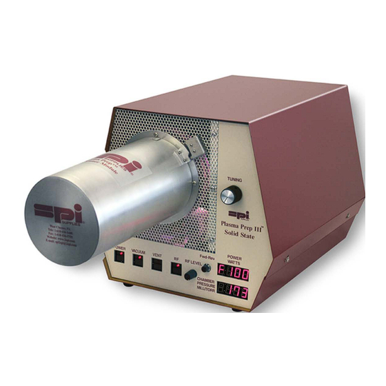
LED selectable push button switch. The Plasma Prep III Plasma Cleaner is a small reactor that weighs under 31 pounds fully assembled, less vacuum pump. With the exception of the external vacuum pump, it is a fully self-contained machine. -
Page 13: Technical Specifications
Technical Specifications Main Body Model No. Plasma Prep III Plasma Cleaner (SPI# 11055-AB or AX) 31 lbs / 14 kg Weight 10.5 inches / 26.7 cm Height Width 11.8 inches / 30.0 cm 14.8 inches / 37.6 cm Length RF Power... -
Page 14: Equipment Controls And Indicators
4.4.1 Front Panel Figure 4.4.1 – Front Panel 1 – Main Power Button – This button controls the main power to the Plasma Prep III Plasma Cleaner. When lit, main power is on. When unlit, main power is off. 2 – Vacuum Button – This button controls the vacuum interlock to the Plasma Prep III Plasma Cleaner. When lit, the chamber is under vacuum. -
Page 15: Rear Panel
10 – Vacuum Inlet – Flange for vacuum hose (NW16) connected to the Plasma Prep III Plasma Cleaner. 11 – Gas Inlet – Gas supply is connected to the Plasma Prep III Plasma Cleaner. This is a barbed fitting for a standard tubing. -
Page 16: Equipment Description
4.5.2 Vacuum System Vacuum System - The vacuum system includes the vacuum pump (not supplied as part of the Plasma Prep III Plasma Cleaner), the vacuum hose, the vacuum valves and the control circuitry. The vacuum valve switch is interlocked with the RF generator switch to prevent the RF power from coming on unless the vacuum valve is energized. -
Page 17: Assembly
not be obstructed. The machine's exhaust (the vacuum pump exhaust) should be vented away from operating personnel. The machine should be far enough away from high voltage equipment to prevent possible high voltage interference. Finally, please ensure the you have the following available: 1) Vacuum pump (See Sec 4.3)) 2) Gas supply –... -
Page 18: Engaging The Tem Specimen Stage Adapter
Figure 5.2.1 – Chamber Cross-section CAUTION Never use metallic screws in place of the nylon screws. Metal, even in small amounts, will short circuit the chamber’s electrodes. 5.2.2 Engaging The TEM Specimen Stage Adapter Close the door with the adapter and ensure that the door latch is secure. Ensuring that the chamber adapter seal is seated against the outer chamber at the O-ring, release the wires retaining the adapter chamber seal and allow the seal to align to the outer chamber. -
Page 19: Connecting The Process Gas
Connect the flexible metal vacuum pipe to the flange connection at the rear of the Plasma Prep III Plasma Cleaner and to the vacuum pump using the O-rings and clamps provided. -
Page 20: Section 6 - Operation
VENT valve switch must be energized. The main power can only be turned off after the vent switch is energized. The Plasma Prep III Plasma Cleaner comes with a BLANK and one or more adapters for your TEM Specimen Stages. These adapters are designed to work with the specific TEM Specimen Stage so that a vacuum good fit is obtained. -
Page 21: Shut Down Procedure
Most operations are on the order of 10 watts, though power as low as one watt can be achieved. NOTE 2: Before the Plasma Prep III Plasma Cleaner is run for the first time, allow the unit to run for one hour before use. This will eliminate any contamination which might be present in the chamber. Either room air or oxygen (O ) can be used for this purpose. -
Page 22: Connecting The Plasma Prep Iii Process Controller
This system provides for multiple gas inputs, either individually or mixed, as well as allowing a process timing of an operation. The Process Controller is placed on top of the Plasma Prep III Plasma Cleaner and is connected through the COMM port in the back of the system. For complete instruction for installation and operation of the Process Controller, please refer to the Plasma Prep III Process Controller manual. -
Page 23: Section 7 - Maintenance
SPI Supplies qualified technicians. O-ring Maintenance The Plasma Prep III Plasma Cleaner has a few o-rings that should be examined at regular intervals. While the low RF wattage that are typically run on this system, will mean longer time periods before the o-rings are degraded and in need of replacement, a careful monitoring of the o-rings will help to keep the system running at good pressures and conditions. -
Page 24: Vacuum System Adjustments
7.4 Vacuum System Adjustments The process gas flow is adjusted by the internal needle valve located at the rear top of the instrument, just after the connector for the gas line. The needle valve is pre-set so that the pressure in the chamber should read approximately 250 mTorr with the chamber empty and without any gas input. -
Page 25: Replacement Parts
REPLACEMENT PARTS Below are typical consumable or replacement parts used in the operation of the Plasma Prep III Plasma Cleaner. For other components not listed here, please contact SPI Supplies. SPI Part Number DESCRIPTION 11008-AB 4” ID Pyrex Inner Chamber 11009-AB 4”... -
Page 26: Section 9 - Technical Diagrams
TECHNICAL DIAGRAMS Figure 9.1 – Logic Flow Chart Version 1.0 9/11... -
Page 27: Figure 9.2 – Plasma Prep Iii Plasma Cleaner Chassis Wiring Diagram
Figure 9.2 – Plasma Prep III Plasma Cleaner Chassis Wiring Diagram Version 1.0 9/11... -
Page 28: Figure 9.3 – Plasma Prep Iii Plasma Cleaner Control Panel Schematic
Figure 9.3 – Plasma Prep III Plasma Cleaner Control Panel Schematic Version 1.0 9/11... -
Page 29: Figure 9.4 – Plasma Prep Iii Plasma Cleaner Rf Control Board Schematic
Figure 9.4 – Plasma Prep III Plasma Cleaner RF Control Board Schematic Version 1.0 9/11...
Need help?
Do you have a question about the plasma prep III and is the answer not in the manual?
Questions and answers