
Related Manuals for Flin Energy 3kVA-24V


Summary of Contents for Flin Energy 3kVA-24V
- Page 1 User Manual FlinSlim Edge Solar Hybrid Inverter With Inbuilt Stabilizer Version: 1.1...
-
Page 2: Table Of Contents
FlinSlim Edge Solar Hybrid Inverter with In-Built Stabilizer Table Of Contents ABOUT THIS MANUAL ........................1 Purpose ..............................1 Scope ..............................1 SAFETY INSTRUCTIONS ........................1 INTRODUCTION ..........................1 Features ............................... 2 Basic System Architecture ........................2 Product Overview ..........................3 INSTALLATION .......................... -
Page 3: About This Manual
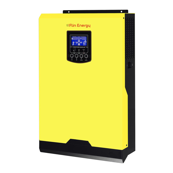
INTRODUCTION This is a multi-function inverter/charger, combining functions of inverter, AVR, solar charger and battery charger to offer uninterruptible power for office and home appliances. Its comprehensive LCD display offers FLIN ENERGY... -
Page 4: Features
Consult with your system integrator for other possible system architectures depending on your requirements. This inverter can power all kinds of appliances in home or office environment, including motor-type appliances such as tube light, fan, refrigerator and air conditioner. Figure 1 Hybrid Power System FLIN ENERGY... -
Page 5: Product Overview
8. Circuit breaker 9. Parallel connectors (only available for parallel models) INSTALLATION Unpacking and Inspection Before installation, please inspect the unit. Be sure that nothing inside the package is damaged. You should have received the following items inside of package: FLIN ENERGY... -
Page 6: Installation
For proper air circulation to dissipate heat, please keep the space around the inverter more than 20 cm. Desktop The inverter can be switched to desktop form factor by following the below steps: FLIN ENERGY... -
Page 7: Battery Connection
It may not be requested to have a disconnect device in some applications, however, it’s still requested to have over-current protection installed. Please refer to typical amperage in below table as required fuse or breaker size. Ring terminal: FLIN ENERGY... - Page 8 Nm . M ake sure polarity at both the batter y and the inverter/charge is correctly connected and ring terminals are tightly screwed to the battery terminals. WARNING: Shock Hazard Installation must be performed with care due to high battery voltage in series. FLIN ENERGY...
-
Page 9: Ac Input/Output Connection
2. Remove insulation sleeve 10mm for six conductors. 3. Insert AC input wires according to polarities indicated on terminal block and tighten the terminal screws. Be sure to connect PE protective conductor ( ) first. →Ground (yellow-green) L→LINE (brown or black) N→Neutral (blue) FLIN ENERGY... -
Page 10: Pv Connection
WARNING! All wiring must be performed by a qualified personnel. WARNING! It's very important for system safety and efficient operation to use appropriate cable for PV module connection. To reduce risk of injury, please use the proper recommended cable size as below. FLIN ENERGY... - Page 11 2. Check correct polarity of connection cable from PV modules and PV input connectors. Then, connect positive pole (+) of connection cable to positive pole (+) of PV input connector. Connect negative pole (-) of connection cable to negative pole (- ) of PV input connector. FLIN ENERGY...
-
Page 12: Communication Connection
SNMP card in the inverter, it will provide advanced communication and monitoring options. After communication cable is connected well, insert bundled CD into a computer and follow on-screen instruction to install the monitoring software. For the detailed software operation, please check user manual of software inside of CD. FLIN ENERGY... -
Page 13: Operation
Fault occurs in the inverter. Flashing Warning condition occurs in the inverter. Function Keys Function Key Description To exit setting mode SELECT To go to next page or next selection ENTER To confirm the selection in setting mode or enter setting mode FLIN ENERGY... -
Page 14: Lcd Display Icons
Three bars will be on and the leftmost bar will flash. Floating mode. Batteries are fully charged. 4 bars will be on. In battery mode, it will present battery capacity. Load Percentage Battery Voltage LCD Display < 1.717V/cell Load >50% 1.717V/cell ~ 1.8V/cell FLIN ENERGY... -
Page 15: Lcd Setting
After pressing and holding ENTER button for 3 seconds, the unit will enter setting mode. Press “SCROLL” button to select setting programs. And then, press “ENTER” button to confirm the selection or ESC button to exit. Setting Programs: Program Description Selectable option FLIN ENERGY... - Page 16 50A (default) chargers. (Max. charging current = utility charging current + solar charging current) Available options in 3KVA model With MPPT: Maximum charging current: To configure total charging current for solar and utility chargers. FLIN ENERGY...
- Page 17 DC cut-off voltage can be set up in program 26, 27 and 29. Restart enable Restart disable Auto restart when overload (default) occurs Restart enable Restart disable Auto restart when over (default) temperature occurs 50Hz (default) 60Hz FLIN ENERGY...
- Page 18 Available options in 48V models: “Solar first” in program 01. 46V (default) Available options in 24V models: Battery fully charged Setting voltage point back to battery mode when 24.5V selecting “SBU priority” or “Solar first” in program 01. 25.5V FLIN ENERGY...
- Page 19 If this inverter/charge r is working in Battery mode or Power priority saving mode, only sol ar energy can charge battery. Solar energy will charge ba ttery if it's available and sufficient. Alarm off Alarm on (default) Alarm control FLIN ENERGY...
- Page 20 If self-defined is selected in program 5, this program can be set up. Setting range is from 24.0V to 29.2V for 24V model, 48.0V to 58.4V for 48V model. Increment of each click is 0.1V. 24V model default setting: 21.0V Low DC cut-off voltage 48V model default setting: 42.0V FLIN ENERGY...
-
Page 21: Display Setting
CPU Version and second CPU Version. Selectable information LCD display Input Voltage=230V, output voltage=230V Input voltage/Output voltage (Default Display Screen) Input frequency=50Hz Input frequency FLIN ENERGY... - Page 22 PV voltage Total charging power=1600W Total charging power Solar charging power Solar charging power=1000W Battery voltage=28.0V, output frequency = 50.0Hz Battery voltage/ Output frequency Main CPU version 1.00 Main CPU version checking Secondary version 1.00 Secondary CPU version checking FLIN ENERGY...
-
Page 23: Operating Mode Description
3K model) Fault mode Note: *Fault mode: Errors are caused PV energy and utility can by inside circuit error or external charge batteries. reasons such over temperature, output short Charging circuited and so on. by PV energy. FLIN ENERGY... -
Page 24: Fault Reference Code
PV energy. The unit will provide output Battery Mode power from battery and PV power. Power from battery only. Fault Reference Code Fault Code Fault Event Icon on Fan is locked when inverter is off. Over temperature FLIN ENERGY... -
Page 25: Warning Indicator
Output power derating Beep twice every 3 seconds SPECIFICATIONS Table 1 Line Mode Specifications INVERTER MODEL 3KVA 5KVA Input Voltage Waveform Sinusoidal (utility or generator) Nominal Input Voltage 230Vac 170Vac± 7V (UPS) Low Loss Voltage 90Vac± 7V (Appliances) FLIN ENERGY... - Page 26 280V Input Voltage *Transfer time may be longer than specified figure when the unit is operated in parallel system. Table 2 Inverter Mode Specifications INVERTER MODEL 3KVA 5KVA Rated Output Power 3KVA/2.4KW 5KVA/4KW Output Voltage Waveform Pure Sine Wave FLIN ENERGY...
- Page 27 @ 20% ≤ load < 50% 20.4Vdc 40.8Vdc @ load ≥ 50% 19.2Vdc 38.4Vdc High DC Recovery Voltage 29Vdc 58Vdc High DC Cut-off Voltage 31Vdc 60Vdc No Load Power Consumption <25W <50W Saving Mode Power Consumption <10W <15W FLIN ENERGY...
- Page 28 FlinSlim Edge Solar Hybrid Inverter with In-Built Stabilizer Table 3 Charge Mode Specifications Table 4 General Specifications 3KVA 3KVA 5KVA 5KVA INVERTER MODEL W/O MPPT With MPPT W/O MPPT With MPPT Safety Certification Operating Temperature Range 0°C to 55°C Storage temperature -15°C~ 60°C FLIN ENERGY...
-
Page 29: Trouble Shooting
The battery voltage is too high. batteries are meet requirements. Fault code 01 Fan fault Replace the fan. Output abnormal (Inverter voltage Reduce the connected load. below than 190Vac or is higher Fault code 06/58 Return to repair than 260Vac) center FLIN ENERGY... -
Page 30: Appendix I: Parallel Function (Only For 5K Model)
Parallel communication cable Current sharing cable 3. Parallel board installation This installation steps are only applied to 5K model. Step 1: Take the dummy board out by unscrewing two screws. Step 2: Disconnect the cable and remove the dummy board. FLIN ENERGY... - Page 31 The cable size of each inverter is shown as below: Recommended battery cable and terminal size for each inverter: Ring terminal: Ring Terminal Torque Cable Dimensions Model Wire Size value D (mm) L (mm) 1*4AWG 33.2 5KVA 2~ 3 Nm FLIN ENERGY...
- Page 32 Note 2: In three-phase parallel system, you can use one 4-pole breaker. The accepted breaker rating is based on the phase current with the maximum units. Otherwise, please follow note 1 instruction. Recommended battery capacity Inverter parallel numbers Battery Capacity 400AH 600AH 800AH 1000AH 1200AH FLIN ENERGY...
- Page 33 WARNING! Be sure that all inverters will share the same battery bank. Otherwise, the inverters will transfer to fault mode. 5-1. Parallel Operation in Single phase Two inverters in parallel: Power Connection Load Communication Connection Three inverters in parallel: Power Connection Load Communication Connection FLIN ENERGY...
- Page 34 FlinSlim Edge Solar Hybrid Inverter with In-Built Stabilizer Four inverters in parallel: Power Connection Load Communication Connection Five inverters in parallel: FLIN ENERGY...
- Page 35 FlinSlim Edge Solar Hybrid Inverter with In-Built Stabilizer Power Connection Load Communication Connection Six inverters in parallel: Power Connection Load Communication Connection 5-2. Support 3-phase equipment Two inverters in each phase: Power Connection FLIN ENERGY...
- Page 36 Note: It’s up to customer’s demand to pick 4 inverters on any phase. P1: L1-phase, P2: L2-phase, P3: L3-phase. Communication Connection Three inverters in one phase, two inverters in second phase and one inverter for the third phase: Power Connection FLIN ENERGY...
- Page 37 FlinSlim Edge Solar Hybrid Inverter with In-Built Stabilizer Load Communication Connection Three inverters in one phase and only one inverter for the remaining two phases: Power Connection Load Communication Connection Two inverters in two phases and only one inverter for the remaining phase: Power Connection FLIN ENERGY...
- Page 38 FlinSlim Edge Solar Hybrid Inverter with In-Built Stabilizer Load Communication Connection Two inverters in one phase and only one inverter for the remaining phases: Power Connection Load Communication Connection One inverter in each phase: FLIN ENERGY...
- Page 39 WARNING: Do not connect the current sharing cable between the inverters which are in different phases. Otherwise, it may damage the inverters. 6. PV Connection Please refer to user manual of single unit for PV Connection. CAUTION: Each inverter should connect to PV modules separately. FLIN ENERGY...
- Page 40 30, it’s necessary to have all inverters connected to PV modules and PV input is normal to allow the system to provide power to loads from solar and battery power. Otherwise, the system will provide power to loads from utility. Fault code display: FLIN ENERGY...
- Page 41 If not, it will display fault 82 in following-order inverters. However, these inverters will automatically restart. If detecting AC connection, they will work normally. LCD display in Master unit LCD display in Slave unit Step 5: If there is no more fault alarm, the parallel system is completely installed. FLIN ENERGY...
- Page 42 For supporting three-phase system, make sure the sharing cables are the inverter is connected in the inverters in the same phase, and disconnected in the detected. inverters in different phases. If the problem remains, please contact your installer. FLIN ENERGY...
-
Page 43: Appendix Ii: Approximate Back-Up Time Table
For upporting three-phase system, make sure no “PAL” is set on #28. If the problem remains, please contact your installer. Appendix II: Approximate Back-up Time Table Model Load (VA) Backup Time @ 24Vdc 100Ah (min) Backup Time @ 24Vdc 200Ah (min) 1100 1200 3KVA 1500 1800 2100 FLIN ENERGY... - Page 44 Backup Time @ 48Vdc 200Ah (min) 1288 1000 1500 2000 2500 5KVA 3000 3500 4000 4500 5000 Note: Backup time depends on the quality of the battery, age of battery and type of battery. Specifications of batteries may vary depending on different manufacturers. FLIN ENERGY...
Need help?
Do you have a question about the 3kVA-24V and is the answer not in the manual?
Questions and answers