
Related Manuals for N-Tron 702-W


Summary of Contents for N-Tron 702-W
- Page 1 702-W and 702M12-W Industrial Ethernet Wireless Devices User Manual & Installation Guide Page 1 of 52 Revision 04062009...
-
Page 2: Table Of Contents
702-W & 702M12-W Industrial Ethernet Wireless Device Installation Guide ............3 Safety Warnings ................................5 Installation ..................................6 Connecting the Unit ..............................14 Web Management and Configuration ........................17 Configuration Guide..............................18 Navigation .................................. 18 System Info Page ..................................19 System Information ................................ -
Page 3: 702-W & 702M12-W Industrial Ethernet Wireless Device Installation Guide
702-W & 702M12-W Industrial Ethernet Wireless Device Installation Guide The N-TRON 702-W Industrial Ethernet Wireless Device offers outstanding performance and ease of use. It is ideally suited for connecting wireless devices to a wired network and connecting two wired networks together where wires are not possible or practical to be installed. - Page 4 In no event shall N-Tron Corp. be liable for any incidental, special, indirect or consequential damages whatsoever included but not limited to lost profits arising out of errors or omissions in this manual or the information contained herein.
-
Page 5: Safety Warnings
Safety Warnings GENERAL SAFETY WARNINGS WARNING: If the equipment is used in a manner not specified by N-Tron Corp., the protection provided by the equipment may be impaired. Contact Information N-Tron Corp. 820 South University Blvd. Suite 4E Mobile, AL 36609... -
Page 6: Installation
Please make sure the N-Tron Wireless Device package contains the following items: 1. 702-W or 702M12-W Wireless Device 2. Three Antennas 3. Product CD Contact your carrier if any items are damaged. Installation Read the following warning before beginning the installation: WARNING Never install or work on electrical equipment or cabling during periods of lightning activity. - Page 7 INGRESS PROTECTION IP67 The classification of degrees of protection provided by the enclosures is defined by IEC 60529. Each rating is defined by specific tests. The IP number is comprised of two numbers, the first referring to the protection against solid objects and the second against fluids.
- Page 8 702-W DIN RAIL MOUNTING Install the unit on a standard 35mm Din-Rail. Recess the 702-W unit to allow at least 3” of horizontal clearance for copper cable bend radius. 19” Universal Rack Mounting DIN-Rail Mounting Most N-Tron™ products are designed to be...
- Page 9 702M12-W BULKHEAD MOUNTING The following are the mechanical dimensions and drill hole placements to consider when mounting the 702M12-W Industrial Ethernet Switches: Page 9 of 52 Revision 04062009...
- Page 10 702M12-W POLE KIT MOUNTING The 702M12-W can be mounted to a pole with N-Tron’s 702M12 Pole Kit (P/N: 702M12-PK). Bracket orientation for small (1” [25mm] dia.) pipe 2x Tighten bolts using 7-8 ft-lb of torque [9.49-10.85 N-m] (all pipe installations) 2x Tighten nuts using 10-11 ft-lb of torque [13.56-14.91 N-m] (all installations)
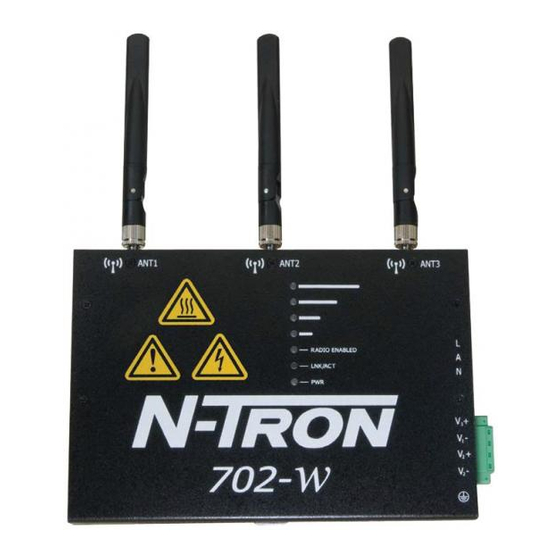
- Page 11 FRONT PANEL From Top to Bottom (M12 only): RJ45 Port Auto Sensing 10/100 Base-TX Connections with PoE Support Power Port PWR LED lights when Power is supplied to the unit LEDs: The table below describes the operating modes: Color Description GREEN Good Signal (user defined) ORANGE...
- Page 12 Use 16-28 gauge wire when connecting to the power supply. The LAN port supports Power over Ethernet and can be used redundantly with the power input mentioned above. Recommended 24V DC Power Supplies, similar to: N-Tron’s P/N NTPS-24-1.3: Input AC 115/230V Power 72W Output DC 24-28V 35 mm DIN-Rail Mountable Output Current 1.3A @ 24V...
- Page 13 Use 16-28 gauge wire when connecting to the power supply. The LAN port supports Power over Ethernet and can be used redundantly with the power input mentioned above. Recommended 24V DC Power Supplies, similar to: N-Tron’s P/N NTPS-24-1.3: Input AC 115/230V Power 72W Output DC 24-28V 35 mm DIN-Rail Mountable Output Current 1.3A @ 24V...
-
Page 14: Connecting The Unit
Use a standard Category 5E straight through or crossover cable with a minimum length of one meter and a maximum length of 100 meters. N-Tron recommends the use of pre- manufactured Cat5E cables to ensure the best performance. If this is not an option and users must terminate their own ends on the Cat5E cables;... - Page 15 Some N-Tron switches have metal din-rail brackets that can ground the switch if the din-rail is grounded. In some cases, N-Tron devices with metal brackets can be supplied with optional plastic brackets if isolation is required.
- Page 16 ~ 2X. Verify that Link LED is ON for the connected port. Verify cabling used between stations. Verify that cabling is Category 5E or greater for 100Mbit operation. SUPPORT Contact N-Tron Corp. at: TEL: 251-342-2164 FAX: 251-342-6353 E-MAIL: N-TRON_Support@n-tron.com WEB: www.n-tron.com...
-
Page 17: Web Management And Configuration
Web Management and Configuration Enter the device’s IP address in any web browser and login to the web management feature of the 702-W. Default: IP Address: 192.168.1.202 User Name: admin Password: admin Page 17 of 52 Revision 04062009... -
Page 18: Configuration Guide
Configuration Guide This guide presents the detailed description of the N-TRON 702-W operating system which is integrated into the N-TRON 702W. N-TRON 702-W Quick Setup Guide describes the configuration steps for the subscriber station (wireless client - bridge). All the configuration settings accessible via web management interface are described in this document. -
Page 19: System Info Page
System Info Page The System Info Page displays a summary of link status information, basic configuration settings of the device (operating mode, network settings), and traffic statistics of all the interfaces. Network administration and monitoring utilities such as antenna alignment, ping test, and speed test tools are accessible via System Info page also. -
Page 20: System Information
ACK Timeout: displays the current ACK Timeout value, which is set on the device manually or adjusted automatically. The ACK Timeout (Acknowledgment Timeout) specifies how long the N-TRON 702-W device should wait for an acknowledgment from a partner device confirming packet reception before concluding the packet must have been in error and requires resending. - Page 21 Host Name: displays the customizable name (ID) of the device as it will appear in popular Router Operating Systems registration screens. LAN MAC: displays the MAC address of the N-TRON 702-W device LAN (Ethernet) interface. LAN IP Address: displays the current IP address of the LAN (Ethernet) interface.
-
Page 22: Statistics Reporting
Statistics Reporting LAN Statistics: section displays the detailed receive and transmit statistics (Bytes, Packets, Errors) of the LAN (Ethernet) interface. These statistics represent the total amount of data and packets transferred between devices through the Ethernet interface from either direction. Both unicast IP traffic (conversations between two hosts using HTTP, SMTP, SSH and other protocols) and broadcast traffic (while addressing all hosts in a given network range with a single destination IP address) is accounted. -
Page 23: Extra Info
Bridge table shows to which bridge port the particular station is associated to - in other words from which interface (Ethernet or wireless ) the network device (defined by MAC address) is reachable to the N-TRON 702-W system while forwarding the packets to that port only (thus saving a lot of redundant copies and transmits). - Page 24 Active firewall entries in the FIREWALL chain of the standard iptables filter table are listed if the device is operating in Router mode. IP and MAC level access control and packet filtering in N-TRON 702-W is implemented using iptables (routing) and ebtables (bridging) firewall which protects the resources of a private network from outside threats by preventing unauthorized access and filtering specified types of network communication.
-
Page 25: Tools
The test is started using the Run Test button. Ping: This utility will ping other devices on the network directly from the N-TRON 702-W device. Ping utility should be used for the preliminary link quality and packet latency estimation between two network devices using the ICMP packets. - Page 26 TraceRoute: Allows tracing the hops from the N-TRON 702-W device to a selected outgoing IP address. It should be used for finding the route taken by ICMP packets across the network to the Destination host. Resolution of the IP addresses (symbolically rather than numerically) can be enabled by selecting the Resolve IP address option.
-
Page 27: Link Setup Page
Wireless Mode: specify the operating mode of the device. The mode depends on the network topology requirements. There are 4 operating modes supported in N-TRON 702-W software: 1. Station: This is a client mode, which can connect to an AP. - Page 28 WDS Peers: WDS Stations and/or WDS Access Points connected to the 702-W Access Point should be specified in this list in order to create a wireless network infrastructure - Wireless Distribution System (applicable for AP WDS mode only). Enter the MAC address of the paired WDS device in the WDS Peer entry field. One MAC address should be specified for Point-to-Point connections.
- Page 29 IEEE 802.11 Mode: This is the radio standard used for operation of your N-TRON 702-W powered device. 802.11b is an older 2.4GHz mode while the 802.11g (2.4GHz) and 802.11a (5GHz) are newer standards based on faster Orthogonal Frequency Division Multiplexing (OFDM) modulation.
-
Page 30: Wireless Security
Access Point in order to get access to the network and all the user data transferred between subscriber station and Access Point will be encrypted if the wireless security methods are used. Security: N-TRON 702-W supports all popular 802.11 security options such as WEP, WPA, and WPA2. Select the security mode of your wireless network: WPA –... - Page 31 EAP – WPA™ or WPA2™ with EAP (Extensible Authentication Protocol) IEEE 802.1x authentication method. This method is commonly used in Enterprise networks. WPA Pre-shared Key: the pass phrase for WPA™ or WPA2™ security method should be specified if the Pre-shared Key method is selected. The pre-shared key is an alpha-numeric password between 8 and 63 characters long.
-
Page 32: Network Page
3 packet filtering and access control in Router mode. Bridge Mode In bridge mode, the N-TRON 702-W will simply forward the network management and data packets to the client PC without any intelligent routing. For some applications, this can provide a more efficient and simple network solution. - Page 33 Bridge Protocol Data Units (BPDU). STP should be turned off (selected by default) when the N-TRON 702-W device is the only bridge on the LAN or when there are no loops in the topology as there is no sense for the bridge to participate in the Spanning Tree Protocol in this case. Note that STP is only supported with WEP encryption.
-
Page 34: Router Mode
Router Mode IP Address: This is the IP address to be represented by the wireless interface of the 702-W. Netmask: This is used to define the host and device classification for the chosen IP address range. 255.255.255.0 is a typical value. -
Page 35: Advanced Page
Advanced Page This page handles advanced routing and wireless settings. The Advanced options page allows you to manage advanced settings that influence the device performance and behavior. The advanced wireless settings are for more technically advanced users who have sufficient knowledge about wireless LAN technology. -
Page 36: Acknowledgment Timeout
Antenna Alignment LED Thresholds The LED's on the 702-W can turn on the LED when received signal levels reach the values defined in the following fields. This allows a technician to easily deploy an N-TRON 702-W CPE without logging into the unit. -
Page 37: Wireless Traffic Shaping
Wireless Traffic shaping feature is dedicated for upstream and downstream bandwidth control while looking from the client (connected on Ethernet interface) perspective. Traffic Shaping: The traffic can be limited by the N-TRON 702-W in the upload and download direction based on a user defined rate limit for each direction. -
Page 38: Service Page
NTP, Web Server, Telnet Server, SSH Server and System Log. Ping WatchDog The ping watchdog sets the N-TRON 702-W Device to continuously ping a user defined IP address (for example the Internet gateway). If it is unable to ping under the user defined constraints, the N-TRON 702- W device will automatically reboot. -
Page 39: Snmp Agent
Simple Network Monitor Protocol (SNMP) is used in network management systems to monitor network- attached devices for conditions that warrant administrative attention. The N-TRON 702-W contains an SNMP agent which allows it to communicate to SNMP managed applications for network provisioning. -
Page 40: Ntp Client, Web Server, Telnet Server
NTP Client, Web Server, Telnet Server NTP Client: The Network Time Protocol (NTP) is a protocol for synchronizing the clocks of computer systems over packet-switched, variable-latency data networks. It can be used to set the N-TRON 702-W internal clock. Web Server: the following N-TRON 702-W Device Web Server parameters can be set: Use Secure Connection (HTTPS): If checked Web server will use secure HTTPS mode. -
Page 41: System Config Page
System Config Page The System Config Page contains Administrative options. This page enables administrator to reboot the device, set it to factory defaults, upload new firmware, backup or update the configuration and establish administrator’s credentials. Firmware Use this section to find out current software version and update the device with new firmware. The device firmware update preserves all configuration settings. -
Page 42: Administrative Account
Administrative Account In this section you can modify the administrator password to protect your device from unauthorized configuration. The default administrator’s password should be changed on the very first setup: Administrator Username: displays name of the system user. Current Password: enter a current password value. Default administrator login credentials: User Name: admin Password: admin... -
Page 43: Common Topology Scenarios
STATION 192.168.1.8 192.168.1.7 PC B 192.168.1.241 PC A 192.168.1.240 Link Setup: Link Setup: Wireless Mode: Wireless Mode: Station SSID: N-Tron ESSID: N-Tron Country Code: United States Country Code: United States 802.11 Mode: 11Ng-20MHz 802.11 Mode: 11Ng-20MHz 10 – 2457MHz Channel:... -
Page 44: Scenario 2 - Encrypted Bridge
STATION 192.168.1.7 192.168.1.8 PC B 192.168.1.241 PC A 192.168.1.240 Link Setup: Link Setup: Wireless Mode: Wireless Mode: Station SSID: N-Tron ESSID: N-Tron Country Code: United States Country Code: United States 802.11 Mode: 11Ng-20MHz 802.11 Mode: 11Ng-20MHz 10 – 2457MHz Channel:... -
Page 45: Scenario 3 - Controls Network
IO Device - 007 192.168.1.43 192.168.1.40 192.168.1.41 Link Setup: Link Setup: Wireless Mode: AP WDS Wireless Mode: Station WDS SSID: N-Tron ESSID: N-Tron Country Code: United States Country Code: United States 802.11 Mode: 11Ng-40MHz 802.11 Mode: 11Ng-40MHz 10 – 2457MHz... -
Page 46: Scenario 4 - Wds Peering
MAC of 192.168.1.7 MAC of 192.168.1.9 Roaming Clients/Stations Link Setup: Link Setup: Wireless Mode: AP WDS Wireless Mode: AP WDS SSID: N-Tron SSID: N-Tron WDS PEERS: WLAN MAC AP2 WDS PEERS: WLAN MAC AP1 Country Code: United States WLAN MAC AP3 802.11 Mode:... -
Page 47: Scenario 5 - Broadband Modem Wireless Router (W/ Dhcp)
192.168.100.3 Interface: ETH0 DHCP Client: Enabled PC C Broadband Modem IP Address: DHCP CLIENT 192.168.100.4 Link Setup: Wireless Mode: SSID: N-Tron Country Code: United States 802.11 Mode: 11Ng-20MHz 10 – 2457MHz Channel: Extension Channel: Output Power: 12dBm Network: Mode: Router... - Page 48 Depth: (w/ DIN-Rail CLIP) Weight (max): 1.93 lbs / 0.88kg Din-Rail mount: 35mm Electrical Redundant Input Voltage: 20-49VDC (Regulated) 702-W Input Current (max): 200mA max. @ 24VDC 702-W Max Power: 4.8Watts Input Ripple: Less than 100 mV N-TRON Power Supply: NTPS-24-1.3 (1.3 Amp@24VDC)
- Page 49 Regulatory Approvals: FCC (EMI): ANSI C63.4-2003: Radio-Noise Emissions US CFR 47, Part 15, Subpart B, Unintentional Radiators Industry Canada ICES-003 Issue 3: Digital Apparatus CE (EMC): EN 61000-4-2 Ed. 1.2 (Electrostatic Discharge) EN 61000-4-3 3rd Ed. (Radio-frequency Electromagnetic Field Amplitude Modulated) EN 301 489-3 V1.4.1 (Radiated Emissions) Page 49 of 52 Revision 04062009...
- Page 50 Weight (max): 3.25 lbs / 1.48kg Din-Rail mount: 35mm (optional) Electrical Redundant Input Voltage: 20-49VDC (Regulated) 702-W Input Current (max): 200mA max. @ 24VDC 702-W Max Power: 4.8Watts Input Ripple: Less than 100 mV N-TRON Power Supply: NTPS-24-1.3 (1.3 Amp@24VDC)
- Page 51 Regulatory Approvals: FCC (EMI): ANSI C63.4-2003: Radio-Noise Emissions US CFR 47, Part 15, Subpart B, Unintentional Radiators Industry Canada ICES-003 Issue 3: Digital Apparatus CE (EMC): EN 61000-4-2 Ed. 1.2 (Electrostatic Discharge) EN 61000-4-3 3rd Ed. (Radio-frequency Electromagnetic Field Amplitude Modulated) EN 301 489-3 V1.4.1 (Radiated Emissions) Page 51 of 52 Revision 04062009...
-
Page 52: N-Tron Limited Warranty
N-TRON, Corp. warrants to the end user that this hardware product will be free from defects in workmanship and materials, under normal use and service, for the applicable warranty period from the date of purchase from N-TRON or its authorized reseller. If a product does not...
Need help?
Do you have a question about the 702-W and is the answer not in the manual?
Questions and answers