
Related Manuals for GARDTEC 872


Summary of Contents for GARDTEC 872
- Page 1 Installation Instructions...
-
Page 2: Table Of Contents
Using Point ID ..........88 New Log Events ..........89 Digi Functions Programming with Point ID ..90 Tone Security Option........90 GardTec 800 Series & DD243 : 2002 ...91 Other New Features ........96 Modem Quick Start (programming) ....97 Nova Active Wiring & Programming ....102 Extended RKP Wiring........107... -
Page 3: Gardtec 872
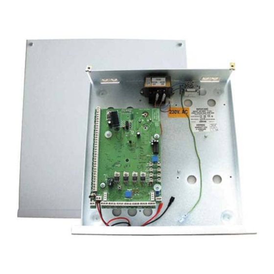
ANT! Input: AC230V +/-10% ~50Hz 125mA Max. 35W Max Nominal Temp Range: 0 - 50°C GardTec 872 Metal Versions For Indoor Use Only GardTec 872 Plastic Versions For Indoor Use Only This equipment is intended only for use as a Security Alarm Control Panel. Adequate ventilation away from heat and humidity must be provided. -
Page 4: Ntroduction
You will find that a little time spent now understanding the GardTec 872 will prove to be a great time saver for the future. It must be stressed that the GardTec 872 is one system that is capable of being split into seven areas. -
Page 5: Codes
A full list of options that are available for the code types are given in the user manual. As a general guide for this section the codes for the GardTec 872 are split into two groups, Global and Area codes. Codes allocated to these groups are as follows:- Global Codes (Controlling All Areas). - Page 6 System Overview GardTec 872 Area Codes (Controlling Specific Areas) Cleaner (Area 0) Area 2 Main 6 Area 3 Main 7 Main 1 Area 4 Main 2 Area 5 Main 3 Area 6 Main 4 Area 7 Main 5 Area 1 These area codes will only control their specific areas.
-
Page 7: Zones
System Overview GardTec 872 Duress If Duress is turned on adding 1 to the first digit of any user code will send a duress signal to central station (e.g. normal code = 5678 the duress code for this would be 6678). -
Page 8: User Names
4 x four wire zones, 8 x two wire zones or 8x two wire EOL zones. Up to sixteen expander boards may be fitted to a GardTec 872 giving a total of 144 zones when configured as 2 wire or 2 wire EOL zones. Each expander board and the control panel zones may use differing wiring configurations. -
Page 9: Keypads
LCD, LED and ACE keypads may be mixed on the same system allowing for total flexibility in control of the system. A maximum of eight keypads/ACE (inclusive of ACE) units may be fitted to the GardTec 872. A maximum of 4 stand alone ACE units may be fitted. -
Page 10: System Installation
YSTEM NSTALLATION Planning The System Time should be taken to plan the system. Because the master control panel may be a blank end station it may be looked upon as an engineer box requiring no attention from the end user. When choosing a location for the master control panel consideration should be given to the following:- The routing of cables, e.g detection, sounders, mains, telephone line, keypads etc. -
Page 11: Control Panel Mounting
The standard GardTec 800 Series keypad is available with a 32 character LCD display or with a twin seven segment LED display. All these keypads require the GardTec 800 Series RKP Housing Part No. 01-063 unless the keypad is to be mounted within the polycarbonate control panel (see Fig 1). - Page 12 System Installation GardTec 872 Fig 1 Polycarbonate Case with Onboard Keypad Mounting Details Page...
- Page 13 GardTec 872 System Installation Fig 2a. Flap to left Standard RKP with Housing Base Use one of the longer springs (supplied) on the tamper switch Fig 2b. Flap to right Standard RKP with Housing Base Use the shorter spring (supplied) on the tamper switch Fig 3.
- Page 14 GardTec 872 System Installation Fig 4 Contour RKP Lower Flap to reveal single cover fixing screw Page...
- Page 15 The new Contour range of stylish remote keypads are also available for the full GardTec 872 control panel. These keypads are designed to be fitted remote from the main control panel and both the LED and LCD versions are available with ACE as standard.
-
Page 16: Wiring
Never tap into lighting circuits that have fluorescent lighting units on them. Mains Supply Connection Mains Wiring only to be carried out by suitably qualified personnel. The mains connection for the GardTec 872 should be as shown in Fig 6. Mains (Twin & Earth) Fig 6. -
Page 17: Keypad Wiring
Wiring Connections GardTec 872 Keypad Wiring Keypads may be wired in 'Star' format (each keypad being wired back to the master control panel) see Fig 7a, or 'Daisy Chain' format (from the control panel to the first keypad then onto the second keypad etc) see Fig 7b. It is also possible to wire the keypads with a mix of 'Star' and 'Daisy Chain' formats see Fig 8. - Page 18 Keypad Terminal Connections Some keypads that are compatible with other Gardiner Technology control panels may have additional markings as well as the GardTec 872 legends. These additional markings are disregarded within this manual. The keypad port on the master control panel is situated on the bottom edge of the PCB towards the right hand side.
- Page 19 Wiring Connections GardTec 872 Fig 10. Multiple RKPs 'Daisy Chain' format. Control Panel DATA DATA SPKR RKP 1 RKP 2 NOTE: RKP terminal positions may differ (dependent on model) Control Panel Fig 11. Multiple RKPs 'Star' format. DATA DATA SPKR...
-
Page 20: Keypad Jumper Options
This information is written to the log as the system is set and unset. If greater than four RKPs are required on the 872 the Multi Keypad option should be programmed to On, two keypads may then share the same ident. - Page 21 GardTec 872 Wiring Connections Note: Instructions for how to program keyfobs to the ACE and using ACE are contained within the LED user manual Page...
-
Page 22: Ace Receiver Wiring & Jumper Options
ACE will be device number one. JP3 (PN) if fitted This jumper is used to select the panel type when ACE is used with the GardTec 350+ or GardTec 580 control panels. The jumper has no use when used with the GardTec 800 Series and should be left in position. -
Page 23: Output Connections
PCB in the master control panel. Warning:- It should be noted that the total output current available for the GardTec 872 is 1 Amp. Any attempt to draw a total current greater than this could result in serious damage to the control panel that is not covered by the manufacturers warranty. - Page 24 GardTec 872 Wiring Connections BATT + & - Factory fitted Sealed Lead Acid battery connections. The GardTec 872 is suitable for the installation of all the popular sizes of alarm batteries. Suggested sizes would be:- 12V 1.2Ah Suitable only for the smallest installations.
- Page 25 Area 3 User 99 Because the GardTec 872 reads the list of users from high to low the log will show for example Set MARY KEY A1 hh/mm/dd/mm. If User numbers are not reserved or allocated then the system will use the first code available (reading high to low) for that particular area set.
- Page 26 GardTec 872 Wiring Connections REMOTE RESET (Note This option may use the Linefault or KS terminal). The Line Fault or the K/S terminal (dependant on option 127 Remote Reset Source) also doubles as the Remote Reset input (normally found on Red-Care STUs sometimes termed as Remote Signal Path).
- Page 27 GardTec 872 Wiring Connections D1 & D2 These terminals are digicom outputs that are fully programmable by the engineer (see Programmable Options Description for more details). The outputs are open collector and have a maximum current sink of 50mA* . On systems only using two channels or systems using the ProDigi or Modem D1 &...
- Page 28 GardTec 872 control panel Modem Patch Lead If the GardTec Modem patch lead is to be used for direct connection to a PC or Lap- Top It should be connected to SK3. The factory fitted link between 12V & Line Fault must be removed.
- Page 29 Wiring Connections GardTec 872 SW+ LATCH New Feature this output is now fully programmable. This terminal is high (+12V) when the system is set and low (0V) when the system is unset. Typical use for this terminal would be the latch signal for PIRs and Shockgards etc.
- Page 30 Wiring Connections GardTec 872 RKP 12V This terminal provides the +12V supply for the keypads and ACE units (see Keypad Wiring for more detail). A maximum current draw of 0.5Amp* is available from this terminal. RKP 0V This terminal is the 0V supply for the keypads and ACE units (see Keypad Wiring for more detail).
- Page 31 Wiring Connections GardTec 872 Fig. 19 Typical output wiring AUX 12V Door locks, Additional Sounders etc. Keyswitch AUX 12V Digital Communicator Red-Care STU Latch signal for Gardscan MX+ PIRs, Shockgards etc. Programmable SW+ Output Strobe Light Module RKP 3 RKP /ACE 1...
- Page 32 Typical Novagard Note: Terminal positions may change dependent on model. The Gardtec 872 may be used with the Novagard Active range of external sounders.When used in Novagard Active mode additional programmable features and diagnostics are available even from a remote location using the Gardtec Remote Software package.
-
Page 33: Zone Connections (4 Wire)
Three wiring methods are possible for the zones located on the main PCB in the GardTec 872 control panel. The first is 4 wire or normal type wiring, if this default option is chosen 8 double pole zones are available (8 alarm zones and 8 tamper zones). - Page 34 Wiring Connections GardTec 872 Fig. 23 Typical 4 Wire Configuration + Supply DETECTOR SUPPLY - Supply ALARM ZONE 1 Normally Closed Alarm Pair + LOOP TAMPER ZONE 1 Normally Closed Tamper Pair - LOOP ALARM Normally Closed Alarm Pair ZONE 2...
-
Page 35: Zone Connections (2 Wire)
GardTec 872 Wiring Connections Zone Connections (control panel 2 Wire option) The second wiring method is Two Wire. This option will give sixteen zones available from the control panel PCB. To use the 2 wire option the control panel should be programmed for 16 (2 WIRE) in the programming section 'PROGRAM ZONE WIRING' (option No.50) - Page 36 Wiring Connections GardTec 872 Fig. 24 Typical 2 Wire Configuration + Supply DETECTOR SUPPLY - Supply Single Passive Infra-Red (Use TZ8 zone for tamper) ALARM ZONE 1 Normally Closed Alarm Pair + LOOP ALARM ZONE 9 Normally Closed Alarm Pair...
-
Page 37: Zone Connections (2 Wire Eol)
GardTec 872 Wiring Connections Zone Connections (control panel 2 Wire EOL option) The third wiring method is Two Wire EOL (End Of Line resistor). This option will give sixteen zones available from the control panel PCB. To use the 2 wire EOL option the control panel should be programmed for 16 (2 WIRE EOL) in the programming section 'PROGRAM ZONE WIRING' (option No.50) - Page 38 Wiring Connections GardTec 872 Fig. 25 Typical 2 Wire EOL Configuration + Supply DETECTOR SUPPLY - Supply Single Passive Infra-Red ALARM ZONE 1 Normally Closed Alarm Pair + LOOP ALARM ZONE 9 Normally Closed Alarm Pair Single Contact - LOOP...
- Page 39 GardTec 872 Wiring Connections Fig. 26 Fig. 27 Double Detector Single Detector Gardscan, Shockgard etc. Gardscan, Shockgard etc. Alarm Alarm Alarm Alarm 4K7 Resistor 4K7 Resistor 6K8 Resistor 6K8 Resistor Alarm Alarm Alarm Zone Wire Link 6K8 Resistor Alarm Zone Fig.
-
Page 40: Zone Expander Cards
GardTec 872 Zone Expander Cards Up to sixteen zone expander cards may be fitted to the GardTec 872. If required one of these expander cards may be plugged directly onto the the main PCB, the other expander cards then being wired to the plug-on card as shown in Fig. 30. Four cores are required for interconnection of the zone expanders. - Page 41 GardTec 872 Wiring Connections Fig. 31a GardTec 872 Zone Expanders (Group1) remote from panel (inc Cable Colours) for EXP1 to EXP8 872 Expander 872 Expander Card(1) Card(2) Expander Cable 1 Black Plug to EXP1 SAD1 SAD1 Yellow LH Molex Connector...
-
Page 42: Zone Expander Card Ident & Zone Allocation41
Wiring Connections GardTec 872 Zone Expander Card Ident & Zone Allocation The panel and each individual card may be programmed as four wire, two wire or two wire EOL wiring modes. All zones on ZEX 1 start at 21 and all zones on ZEX 2 start at 31 and so on. - Page 43 GardTec 872 Wiring Connections EXP5 JP5 On 4 Wire 2 Wire 2 Wire EOL AZ1 Zone AZ2 Zone AZ3 Zone AZ4 Zone TZ1 Zone 61 Tamper TZ2 Zone 62 Tamper TZ3 Zone 63 Tamper TZ4 Zone 64 Tamper EXP6 JP6 On...
- Page 44 Wiring Connections GardTec 872 Group 2 Expanders using SAD2 from panel to SAD1 terminal on Expander EXP9 JP1 On 4 Wire 2 Wire 2 Wire EOL AZ1 Zone AZ2 Zone AZ3 Zone AZ4 Zone TZ1 Zone 101 Tamper TZ2 Zone...
- Page 45 Wiring Connections GardTec 872 EXP13 JP5 On 4 Wire 2 Wire 2 Wire EOL AZ1 Zone AZ2 Zone AZ3 Zone AZ4 Zone TZ1 Zone 141 Tamper TZ2 Zone 142 Tamper TZ3 Zone 143 Tamper TZ4 Zone 144 Tamper EXP14 JP6 On...
- Page 46 'Normal (4 wire)', 'Two Wire' or 'Two Wire EOL. When used to full capacity this allows the GardTec 872 to have up to 16 control panel zones plus 60 ID zones. Radio Expanders cannot be used if ID Expansion has been chosen.
-
Page 47: Radio Expander Modules
Pin4 SCLK SCLK EXP2 Pin3 SAD2 SAD2 Once the Radio Expander Card has been connected to the GardTec 872 control panel it should be connected to the Radio Receiver as follows:- Radio Expander Card to Radio Receiver Wiring Black Black... -
Page 48: Output Expander Modules (Opx)
GardTec 872 Output Expander Modules (OPX) Up to four output expander modules may be fitted to the GardTec 872 control panel. These modules may, if required be wired in a chain of zone expanders or on a separate leg(s). The zone expanders only require four cores for interconnection, if Output Expanders are used on the same leg five cores will be required (see page 38). -
Page 49: Engineers Rkp Connection
ENG RKP. The connector is 'keyed' and will only fit in one orientation, the use of force should be avoided to prevent damage to the plug or socket. The GardTec 872 Control Panel must be programmed via an LCD Keypad. The keypad wiring colours for the Engineers RKP lead are as follows. -
Page 50: Printer Connection
Wiring Connections GardTec 872 Printer Connection The GardTec 872 has an RS232 port that may be connected to a standard serial printer, to facilitate this two printer leads are available from GardTec Ltd. Printer Cable No. 1 Part No 01-091 Connects from PCB direct to printer Printer Cable No. -
Page 51: Areas
Three Areas are shown in this example, the GardTec 872 has 7 areas available Page... -
Page 52: Zones
Areas, Zones & Output Types GardTec 872 Fig. 35 Typical Area Layout Zones situated in Area3:- Area 3 Zone 5 Stores Zone 6 Zones situated in Zones situated in Area1:- Area2:- Zone 1 Zone 3 Zone 2 Zone 4 Zones situated in... - Page 53 GardTec 872 Areas, Zones & Output Types The User codes that are allocated to the system shown in Fig. 35 are:- User No. User Type Functions Available Master Set/Area Sets/Part Set/Unset Remove Zones Test Zones View Log Change Chime Change User Codes...
-
Page 54: Zone Type Terminology
Areas, Zones & Output Types GardTec 872 Zone Type Terminology (Zone Types) Each zone has a default type that may be re-programmed. Below is an explanation of the terminology used for zone types. 12 Hour Zone active when Control Panel is Set. -
Page 55: Zone Type Terminology Areas/Attributes
GardTec 872 Areas, Zones & Output Types Zone Type Terminology (Areas & Attributes) When programming the zone types other zone attributes including area allocation may be programmed within the same screen. Please refer to the breakdown of the Zone programming screen below. - Page 56 Areas, Zones & Output Types GardTec 872 Rem -/Dk Zone cannot be removed (omitted) by end user and is also Double Knock. Zone is turned Off. Norm.Ky Zone is a Normal Type Keyswitch Zone. Bias.Ky Zone is a Bias Type Keyswitch Zone.
-
Page 57: Output Type Terminology
GardTec 872 Areas, Zones & Output Types Output Types Terminology There are two groups of outputs types available. General Outputs. These are available on the following terminals Detector Reset Terminal Latch Terminal On-Board Relay Terminals (com, N/O, N/C) PGM 3 Terminal (Strobe Terminal) - Page 58 Areas, Zones & Output Types GardTec 872 Will activate for the duration of the entry exit times Bell Will activate when the bell is triggered and will cut of with the bell time Alert Will activate when an alert zone is triggered...
- Page 59 GardTec 872 Areas, Zones & Output Types Latch Any Will activate when panel is set and will reset when entry timer starts Any Set Will activate when panel is set and will reset when panel is unset Power Fail Will activate when aux. power falls below 10.6 volts Power OK Output is active and changes over when the battery volts fall below 10.6 V...
- Page 60 Communications Outputs. These are available on the following terminals D3 (PA terminal) D4 (12Hr terminal) Digicom Channels (when used with GardTec ProDigi or Digi / Modem) Below is given a list of Output Types with a brief description of the option. Output not used...
- Page 61 GardTec 872 Areas, Zones & Output Types Alarm B Will activate when a second zone has alarmed (The activation of this output is dependent upon other system attributes) Please refer to the DD243 Section within this manual. Alarm Abort Will activate when the panel is in alarm and unset within the programmed abort time .
- Page 62 Areas, Zones & Output Types GardTec 872 Area 1-7 Fire Will activate when a selected area fire zone is triggered. Perimeter Will activate when a perimeter zone is triggered. Zone Exclude Will activate when the panel auto rearms with a zone in fault condition. It is a requirement of DD243 that a zone that is auto excluded is reported to central station.
- Page 63 ROGRAMMING GardTec 872 Programming To program the GardTec 872 the engineer must first enter the programming routine by entering the engineer code (factory default 1234), The LCD display will then show:- Do you want to . . Use ENGNR. Mode ? (LED displays will show Press YES to enter into the programming routine.
-
Page 64: Programming
Programming GardTec 872 Menu Shortcut Numbers Due to the vast range of features available on the GardTec 872 control panel an LCD keypad must be used for programming. For DD243:2002 options please refer to page 85. Menu No. Jumps to... - Page 65 GardTec 872 Programming Menu No. Jumps to No. of Keypads / Multi On Off / Keyswitch Zone Re-Arm / Double Knock Time Engineer Code Remote Reset / Line Fault Source Line Fault Sounders Line Fault Mode Line Fault Log Duress On Off...
- Page 66 Programming GardTec 872 Menu No. Jumps to Expander 1 O/P1 Mode Timer 2 On Time Timer 2 On Time Timer 2 Off Time Timer 2 Off Time Timer 3 On Time Timer 3 On Time Timer 3 On Time Timer 3 Off Time...
- Page 67 GardTec 872 Programming Menu No. Jumps to Part 1 Exit Time / Exit Mode Area 2 Part 2 Exit Time / Exit Mode Area 2 Part 3 Exit Time / Exit Mode Area 2 Full Set Exit Time / Exit Mode Area 3...
- Page 68 Programming GardTec 872 Menu No. Jumps to Confirm Start Delay ACE Battery Monitor On Off Strobe Timer Strobe Trigger Custom 1 OP Mode (zone / code) / No. / Period / Mode Custom 2 OP Mode (zone / code) / No. / Period / Mode Custom 3 OP Mode (zone / code) / No.
- Page 69 GardTec 872 Programming Menu No. Jumps to Bell Delay Time Area 7 Full Set Exit Time / Exit Mode Area 7 Part 1 Set Exit Time / Exit Mode Area 7 Part 2 Set Exit Time / Exit Mode Area 7...
-
Page 70: Zone Descriptor Programming Template
Programming GardTec 872 Zone Descriptor Programming Template When programming Zone Descriptors (or User Names) please use the template below for the allocation of keys to characters 1 = ABC 2 = DEF 3 = GHI 4 = JKL 5 = MNO... -
Page 71: Understanding Part/Test/Chime
GardTec 872 Programming Understanding Part/Test/Chime in Zone Attributes Section Part Sets Three Part Set modes are available on all models. These are Part1, Part 2 & Part3. Part Set 1 may consist of a suite of zones that have been programmed as Part1 by the engineer. -
Page 72: Program Orders
Programming GardTec 872 Program Orders As previously mentioned an alternative to entering option numbers with an LCD keypad is to scroll through the programmable options using the YES and NO keys. To do this enter the engineer code followed by YES, the display will show:- Program . - Page 73 GardTec 872 Programming Headers & Options Headers & Options Digicom Sounder Levels Type or Test Chime Level Start Delay Entry/Exit Level Channels Key Beep Level Digicom Functions (Digigard / ProDigi /Modem) Sens./ Xp/Custom Line Fault Modes Sensor Output (Det Reset)
- Page 74 Programming GardTec 872 Headers & Options Headers & Options Engineer Code Alarm Confirm Engineer Code Engineer Code Locked/Unlocked Window Time On Entry Sounder Mode Service Reset Mode Secondary Time Service Timer On/Off ET Mode Time To Next Service Bell Mode Service Tel No.
- Page 75 & R PECIFICATION ECORDS GardTec 872 Control Panel Specification Power Input 230V a.c +/- 10% @ 50Hz Max Loop Resistance 2K (not with E.O.L) Loop Delay Time 600 milliseconds FUSES Bell 1A Quick Blow R.K.P 500mA Quick Blow 1A Anti-surge...
-
Page 76: Gardtec 840 S
Specification & Records GardTec 872 Number Of Keypads 4 Normal 8 using Multi Option ACE compatible Onboard Relay Rating 24V 1A S.P.C.O Zone Descriptors 16 Characters (last 3 omitted with tamper) Max No of Users 99 + Engineer Default Codes... -
Page 77: System Settings Record
Specification & Records GardTec 872 System Settings Record Zone No. Descriptor Area(s) Loop Ohm V @ Sensor Part Info Example Living Room 1&2 14 AZ 4 TZ 13.2V A1 P1 Page... - Page 78 Specification & Records GardTec 872 Zone No. Descriptor Area(s) Loop Ohm V @ Sensor Part Info Page...
- Page 79 Specification & Records GardTec 872 Zone No. Descriptor Area(s) Loop Ohm V @ Sensor Part Info Page...
- Page 80 Specification & Records GardTec 872 Zone No. Descriptor Area(s) Loop Ohm V @ Sensor Part Info Page...
- Page 81 Specification & Records GardTec 872 Aux Current (mA) Bell Current (mA) RKP Current (mA) Customer Name:- Contact Name:- Tel No:- Fax No:- Modem No:- Customer Address:- Other:- Service Due Dates Completed Date Signature Page...
-
Page 82: Miscellaneous
ISCELLANEOUS Resetting to Factory Defaults When resetting the GardTec 800 Series to factory defaults several levels of resetting are available, these are:- Pressing 1, 9, YES, NO during initial power up will revert the Master Code and Engineer Code (not locked engineer code) back to factory defaults. -
Page 83: Engineer Reset After An Alarm
GardTec 872 Miscellaneous Engineer Reset After An Alarm If a system is programmed for engineer reset it will be necessary for the engineer to attend the system. After the engineer has confirmed the integrity system the system should be reset as follows:- The system must be unset Unset, Do you want to . -
Page 84: Diagnostics
GardTec 872 Miscellaneous Diagnostics The GardTec 872 control panel has several engineering diagnostic features available via an LCD keypad. To access these diagnostics follow the steps below With the display showing:- < < < < UN-SET > > > >... - Page 85 GardTec 872 Miscellaneous Change / List Press NO. The display will show:- Diagnostics ? Press YES. The display will show for example:- Battery Test = 01 Hrs Aux. Volts Press YES. The display will show for example:- 13.6 Battery Volts Press YES.
- Page 86 GardTec 872 Miscellaneous Press YES. The display will show for example:- On-Charge (V) (for Novagard Active battery) Press YES. The display will show for example:- On-Charge (V) (for Novagard Active battery) Press YES. The display will show for example:- Hold-Off (V) (for Novagard Active hold-off volts) 13.6...
-
Page 87: Zone Programming Tutorial
GardTec 872 Miscellaneous Zone Programming Tutorial Below is a Zone Programming Tutorial that shows how a single zone is programmed. This should be repeated for all zones that require programming. With the display showing:- < < < < UN-SET > > > >... - Page 88 GardTec 872 Miscellaneous Press Yes. The Zone Type you have chosen will be accepted and the chevron will move along to the last character on the top line:- 001 = Ent/Ex A > = Remove - We are now programming what Area(s) the Zone will be allocated to.
-
Page 89: Using Point Id
Using Point ID The ProDigi Communicator or GardTec Modem from GardTec may, if required be used to allow Point ID communication with the GardTec 872. When used in this mode the ProDigi/Modem will use the Ademco Point ID Protocol. Point ID allows for the transmission of zone and detector types to be transmitted along with the alarm information. -
Page 90: New Log Events
Appendix 1 GardTec 872 New Log Events Two new log events have been added with the implementation of Point ID these are:- Alarm Abort The LCD display will show "Alarm Abort" along with the time and date whilst the LED will show "... -
Page 91: Digi Functions Programming With Point Id
GardTec 872 Series Appendix 1 Engineer Code Entered New Log Event of Engineer Code Entered has been added. Digi Functions Programming With Point ID All normal Digi functions should be programmed as usual with the exception of the following items that have no function with Point ID protocol. -
Page 92: Gardtec 800 Series & Dd243 : 2002
Northern Ireland replacing the 1999 policy. All communications systems that require a Police URN will need to conform to DD243:2002. This document is intended to help installers of the GardTec 872 control panels understand the new features that have been incorporated into the panels and use them to ensure that the system complies to the new DD243:2002 requirements. - Page 93 Appendix 1 GardTec 872 Confirm Secondary Time Window (default = 60 minutes) This time window may be programmed between 1 and 120 minutes we would suggest a time between 30 and 60 minutes but should typically be the same time as the confirm time window.
- Page 94 Appendix 1 GardTec 872 Keypad Opening Options available are:- Always On Keypad is always active. Off in Entry Keypad will not operate during Entry Times 1 & 2. Once Entry Time has expired the keypad may be used. Off in Ent/Alm...
- Page 95 Other DD243:2002 Notes to Consider When a system auto re-arms with a zone in fault condition The GardTec control panel will omit the zone concerned. A signal should be sent to the central station indicating that a detector(s) has (have) been isolated.
- Page 96 Appendix 1 GardTec 872 Scenario Unlocking the initial entry door disables all means of conformation 6.4.3 DD243:2002. Event 1 System Set Event 2 Entry Door Unlocked Confirmed Alarms Disabled Event 3 Open Entry Door (entry time starts) Event 4 Entry Time Expires (inc Entry Time 2)
-
Page 97: Other New Features
Fuse / Bat Fault will be generated. This option may be turned off by setting the PSU test time to 0 in the diagnostic section. Zone Expansion Zone Expansion for the GardTec 872 starts at zone 21 for the first expansion zone for all types of expansion options. Page... -
Page 98: Modem Quick Start (Programming)
Appendix 1 GardTec 872 Modem Quick Start The Gardtec 872 control panel may be programmed on site via the keypad or via Gardtec Remote Software. In order to program the panel via Gardtec Remote the communications needs to be initialised. - Page 99 Appendix 1 GardTec 872 Enter 34 followed by YES display will show. Digicom Type ..= Mod + F / F Press YES Display will show. Test Digicom Channels ? Press NO four times. Display will show.
- Page 100 Appendix 1 GardTec 872 Press YES. Display will show. Site ID Code is Un-Programmed (Site ID Code is issued by central station. If you are given a six digit code only use the last four digits) Press NO. Display will show.
- Page 101 Appendix 1 GardTec 872 Press YES or NO as required Line Monitor Display will show. = Tone + Volts For Dedicated line use Tone + Volts. For Shared line use Line Volts. Press NO until the required setting is shown.
- Page 102 Appendix 1 GardTec 872 Press YES. Display will show. Channel 1 2 3 4 5 6 7 8 R/Rep 0 0 0 1 0 0 0 0 This is channel Restore Report i.e when system is reset channel is reported clear to Central Station Channel 1 2 3 4 5 6 7 8 Press NO.
-
Page 103: Nova Active Wiring & Programming
Gardtec 872 control panel. As you would expect a variety of formats and sounder out- puts are available that may be wired in standard format to all makes of control panels or in a serial format to the Gardtec 872 control panel. When wired in serial format the Novagard Active offers the following features. - Page 104 Appendix 1 GardTec 872 Novagard Active Diagnostic screen shots (from Gardtec Remote). Wiring Connections & Jumper Positions. Serial Connection to Gardtec 872 control panel Novagard Active Terminals BELL TMPR BELL UNIT 1 BELL - BELL + Connection HOLD - BELL...
- Page 105 Appendix 1 GardTec 872 Programming < < < < UN-SET > > > > 1) With the display showing:- 01 Jan 00: 00: 01 2) Enter the Engineer code (1234 default) Do you want to . . The display will show:- Use ENGNR.
- Page 106 Appendix 1 GardTec 872 Press NO to change the LED pattern, choose from Alternating LEDs Single Static LED Twin Flashing LEDs When finished press YES NovA1 = Off LEDS = 0 11) The chevron will now move to the Confirm option:- Confirm >...
- Page 107 Appendix 1 GardTec 872 17) The chevron will now move to the Alarm NovA1 A1 = 1 PA = 0 sounder pattern option:- Alarm > 0 Tamper = 0 18) Press NO to select the sounder pattern required as shown in step 16. When finished press YES.
-
Page 108: Extended Rkp Wiring
Appendix 1 GardTec 872 Extending RKP Wiring to 500mtrs Page... -
Page 109: Extended Expander Wiring
Appendix 1 GardTec 872 Extending Expander Wiring to 500mtrs Page... -
Page 110: Secure Redcare Stu Wiring
Appendix 1 GardTec 872 Typical Secure Wiring to RedCare STU from Output Card. The preferred method for secure Comms Channel Wiring is shown below for a single channel. The security in this format is greater than using Latch / On-board Relay / Det Reset Terminal(s) and is therefore recommended. - Page 111 Appendix 1 GardTec 872 Page...
- Page 112 GardTec Ltd Tel: 0161 655 5500 Fax: 0161 655 5501 Internet: www.gardtec.ltd.uk e-mail: sales@gardtec.ltd.uk Technical Support: 0161 655 5600 Technical Support Fax: 0161 655 5610 PR5406 Rev1.0...
Need help?
Do you have a question about the 872 and is the answer not in the manual?
Questions and answers