Table of Contents
Advertisement
Installation - USE AND MAINTENANCE MANUAL
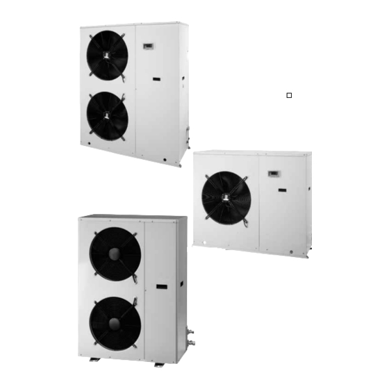
Cooling only air cooled condensing
units and heat pumps with axial fans.
HCAT TE
0011÷0121
HCAN TE
0071÷0121
Advertisement
Table of Contents

Related Manuals for Eco HCAT TE 0011

Summary of Contents for Eco HCAT TE 0011
- Page 1 INSTALLATION - USE AND MAINTENANCE MANUAL Cooling only air cooled condensing units and heat pumps with axial fans. HCAT TE 0011÷0121 HCAN TE 0071÷0121...
- Page 3 INDEX General warnings Cooling performance HCAN TE Fundamental safety rules Heating performance HCAN TE Identification Operating limits Receiving and handling the product Checking and starting up the unit Description of standard unit Activating and deactivating the unit Dimensional drawings Setting and displaying service parameters Installation Alarm display Refrigerant connections...
- Page 4 GENERAL WARNINGS These appliances have been designed for cool- The documentation supplied with the unit ing and/or heating and must be used for this pur- must be consigned to the owner who should keep pose in applications compatible with their perfor- it carefully for future consultation in the event of mance characteristics.
- Page 5 IDENTIFICATION HCAT TE and HCAN TE condenser units can be identi- Tampering with or De' Longhi S.p.a. - 31100 Treviso / Italia Via L.Seitz, 47 - tel. 04224131 fax 0422413659 fied by the: removal MODEL: VOLTAGE: absence of rating plates or CODE: Packaging label other means enabling the...
- Page 6 EC directive 89/392. They are with external equaliser, 4-way reversal valve and liquid factory tested and on site installation is limited to the receiver (HCAN TE and HCAT TE 0011÷0061). Safety pres- water and electrical connections. sure switches to control delivery and intake pressure.
-
Page 7: Dimensional Drawings
DIMENSIONAL DRAWINGS MODELS 0011÷0061 compressor condensing/evaporating coil electrical panel axial-flow fans liquid line connection gas line connection power line input (0071÷0121) lifting holes Models 0071-0091 are fitted with the top fan only. SOLLEVAMENTO LIFTING MODELS 0071÷0121 Ø35 UNITÁ 101-121 UNIT 101-121 Dimension 0011 0021... -
Page 8: Refrigerant Connections
REFRIGERANT CIRCUIT HCAT TE Flared connection Compressor Heat exchanger 3-way valve (liquid side) Oil sump heater Liquid receiver (HCAT TE 0011÷0061) Filter High pressure switch 3-way valve (gas side) Low pressure switch Flared connection Pressure tap... - Page 9 REFRIGERANT CIRCUIT HCAN TE Gas line valve Cycle reverse valve Low pressure switch Liquid line valve Thermostatic valve Gauge connections Compressor Liquid indicator Oil sump heater Filter Finned coil Nonreturn valve Liquid receiver High pressure switch The units are pre-filled with a sufficient quantity of refrig- 4.
- Page 10 MODELS 0071÷0121 Fig. 3 Fig. 1 Fig. 2 SIZING OF REFRIGERANT PIPES SIZING CONNECTION PIPING IN RELATION TO EQUIVALENT DISTANCE Model 0011 0021 0025 0031 0041 0051 0061 0071 0091 0101 0121 Type of pipe 0-10 m eq. Intake / Discharge Ø...
- Page 11 EQUIVALENT CORRESPONDING LENGTH, 90° CURVE AND COMPLETE SIPHON Pipe diameter Øi / Øe 8/10 10/12 14/16 16/18 20/22 26/28 33/35 39/42 90° curve m eq. 0,40 0,42 0,48 0,50 0,60 0,80 1,00 1,20 Siphon m eq. 1,60 1,68 1,92 2,00 2,40 3,20 4,00...
- Page 12 models 0011-0091 models 0101-0121 LIQUID VALVE GAS VALVE CHECKING FOR LEAKS 4. Connect the nitrogen cylinder to the valves and bring 1. Check that the valves on the external unit are the circuit up to a pressure of 1,200 kPa; completely closed;...
- Page 13 This should have a delayed characteristic curve, contacts opening by at least 3 mm and an adequate interruption and differential protection capacity. ELECTRICAL DATA HCAT TE 0011÷0121 / HCAN TE 0071÷0121 Rated values (1) Size Electrical power Compressors...
- Page 14 ELECTRICAL PANEL The electrical panel is located inside the unit at the top of the technical compartment where the various components of the refrigerant circuit are also to be found.To access the electrical panel, remove the front panel of the unit by undoing the self- tapping screws.To access the components in the electrical pan- el and the terminal boards, undo the four screws on the panel itself.
- Page 15 LAYOUT ELECTRICAL PANEL HCAT TE-HCAN TE 0071÷0121 THREE-PHASE Radio interference suppresser Electronic controller Fan/s control electronic board Interference suppresser capacitor C2-3 Fan start capacitor/s FU1 Transformer protection fuse FU2 Auxiliary circuit protection fuse FU3 Fan/s fuse KA1 High pressure switch relay mode KA3 Defrosting relay KA4 Winter control relay...
- Page 16 0011-0025 SINGLE-PHASE WIRING DIAGRAM Outline wiring diagram, refer to the diagram on the electrical panel of the unit. English 04/03 HCAT TE - HCAN TE...
- Page 17 0011-0025 THREE-PHASE WIRING DIAGRAM Outline wiring diagram, refer to the diagram on the electrical panel of the unit. HCAT TE - HCAN TE English 04/03...
- Page 18 0031 SINGLE-PHASE WIRING DIAGRAM Outline wiring diagram, refer to the diagram on the electrical panel of the unit. English 04/03 HCAT TE - HCAN TE...
- Page 19 0031÷0061 THREE-PHASE WIRING DIAGRAM Outline wiring diagram, refer to the diagram on the electrical panel of the unit. HCAT TE - HCAN TE English 04/03...
- Page 20 0041÷0061 THREE-PHASE WIRING DIAGRAM Outline wiring diagram, refer to the diagram on the electrical panel of the unit. English 04/03 HCAT TE - HCAN TE...
- Page 21 0071÷0121 THREE-PHASE WIRING DIAGRAM Outline wiring diagram, refer to the diagram on the electrical panel of the unit. HCAT TE - HCAN TE English 04/03...
- Page 22 0071÷0121 230V THREE-PHASE WIRING DIAGRAM Outline wiring diagram, refer to the diagram on the electrical panel of the unit. English 04/03 HCAT TE - HCAN TE...
- Page 23 TECHNICAL DATA Size HCAT TE 0011 0021 0025 0031 0041 0051 0061 0071 0091 0101 0121 Cooling capacity (1) 11,9 14,4 17,5 20,5 25,7 29,8 36,7 Compressor absorbed power (1) 10,9 No. of fans N° Min. rotation speed Max. rotation speed Max.
- Page 24 COOLING PERFORMANCE HCAT TE Size HCAT 0011 TE Size HCAT 0021 TE Size HCAT 0025 TE Size HCAT 0031 TE Size HCAT 0041 TE Size HCAT 0051 TE 10,3 10,8 11,4 11,4 12,0 12,7 13,4 14,1 13,9 14,7 15,5 16,3 17,8 10,4 11,0 11,1 11,6 12,3 12,9 13,6...
- Page 25 Size HCAT 0101 TE Size HCAT 0121 TE 28,0 30,0 32,0 34,1 36,2 36,5 39,0 41,7 44,4 47,1 26,6 28,5 30,4 32,4 34,4 34,6 37,0 39,6 42,1 44,8 26,0 27,8 29,7 31,7 33,7 33,8 36,2 38,7 41,2 43,8 25,1 26,9 28,7 30,6 32,6 32,6 35,0 37,4 39,8 42,4 10,0...
-
Page 26: Operating Limits
HEATING PERFORMANCE HCAN TE Size HCAN 0071 TE Size HCAN 0091 TE Size HCAN 0101 TE 16,7 16,6 16,6 21,4 21,2 21,1 24,4 24,3 24,3 19,3 19,2 19,1 18,9 24,6 24,4 24,2 24,0 28,2 27,9 27,7 27,4 21,5 21,6 21,7 21,4 21,0 29,6 28,6 27,6 27,1 26,6... -
Page 27: Checking And Starting Up The Unit
CALIBRATION OF PROTECTION DEVICES Opens Closes RESET (bar) (bar) High pressure switch HCAT TE 28,0 23,0 manual Low pressure switch HCAT TE automatic High pressure switch HCAN TE 28,0 18,0 manual Low pressure switch HCAN TE automatic SOUND PRESSURE LEVEL Octave band (Hz) Metres Size... - Page 28 STARTING UP FOR THE FIRST TIME (after two hours) - Replace the inspection panel Before activating the condenser unit: - Make sure the remote mains switch QF1 is in the OFF position; - Remove the inspection panel; - Place the main switch of the unit QF (outside of the unit) in the “ON”...
- Page 29 Heating LED Cooling LED mode MODE-UP key Compressor LED Defrosting LED ON/OFF-DOWN key ALARM RESET Heater LED HSA3 Power LED Values display Activating: Deactivating: - Press the ON/OFF button on the keyboard in the figure. - Press the ON/OFF button on the keyboard in the figure. mode mode HSA3...
- Page 30 ACTIVATING AND DEACTIVATING THE UNIT Heating and cooling functions are enabled and disabled via To activate and deactivate the unit, see page 23. the control panel. SETTING AND DISPLAYING SERVICE PARAMETERS DISPLAYING SERVICE PARAMETERS To display service parameters, proceed as follows: Use the keys to set a new value;...
- Page 31 If the parameters set on the microprocessor require verifi- - press the ON/OFF and MODE keys together for one cation or modification, a password must be used to enter a second; higher level, accessible to authorised service centres only. mode Follow the instructions below: C0 1 - press the ON-OFF key;...
- Page 32 LIST OF ACCESSIBLE - DISPLAYABLE PARAMETERS Parameter Description Unit of measurement Appliance configuration parameters Value Compressor parameters Value Fan parameters Value Alarm parameters Value Note: while the parameters are being set, the COMPRESSOR and ELECTRIC RESISTOR LEDs flash, alternating with the DEFROSTING LED.
-
Page 33: Shutting Down For Long Periods
OPERATING CHARACTERISTICS START UP AND SHUT DOWN DEFROSTING To start up and shut down the unit, use the QS1 discon- In heating mode during extremely cold conditions or with nector switch. This turns on power to the compressor oil high relative humidity, frost or ice may form on the exter- sump heater and places the electronic board in stand-by. - Page 34 EXTRAORDINARY MAINTENANCE CHEMICAL WASHING In the event of partial leaks, the circuit must be You are recommended to chemically flush the plate heat completely emptied before being refilled. The units must be filled during the liquid exchanger after every 3 years of operation. For instruc- tions on how to carry out this operation, contact the man- phase only.
-
Page 35: Troubleshooting
TROUBLESHOOTING MALFUNCTION CAUSE REMEDY Check for presence of voltage The condenser unit does No voltage Check safety systems not start upstream of the appliance Check power line Supply voltage too low Main unit switch in OFF position Position in ON Automatic switch in the OFF position Check No demand from internal unit... - Page 36 MALFUNCTION CAUSE REMEDY High external air temperature High internal air temperature High discharge pressure Check Excessive refrigerant content External condenser clogged Check fan operation Insufficient air flow to condenser Check pump operation Faulty fan control Check Insufficient gas content Check Low discharge pressure Low external condenser air temperature Check...
- Page 40 G R O U P Dé Longhi Group - Via L. Seitz, 47 - 31100 Treviso (Italia)
Need help?
Do you have a question about the HCAT TE 0011 and is the answer not in the manual?
Questions and answers