Table of Contents
Advertisement
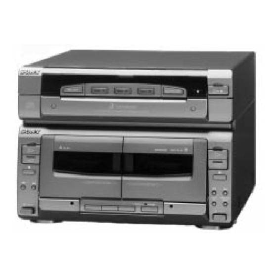
SERVICE MANUAL
HCD-W55 is the deck, CD section
r
in MHC-W55/W77AV.
Dolby noise reduction manufactured under license from
Dolby Laboratories Licensing Corporation.
"DOLBY" and the double-D symbol a are trademarks of
Dolby Laboratories Licensing Corporation.
CD player section
System
Compact disc digital
audio system
Laser
Semiconductor laser
(λ =780nm)
Emission
duration : continuous
Laser output
Max 44.6µW*
*This output is the value measured at a distance
of 200 mm from the objective lens surface on
the Optical Pick-up Block with 7 mm aperture.
Wavelength
780–790 nm
Frequency response
2Hz–20kHz (±0.5 dB)
Signal-to-noise ratio
More than 80 dB
Dynamic range
More than 90 dB
CD OPTICAL DIGITAL OUT
(Square optical connector jack, rear panel)
Wavelength
Output Level
MICROFILM
CD
Section
Tape deck
Section
SPECIFICATIONS
Tape player section
Recording system
Frequency response
Wow and flutter
Design and specifications are subject to change without notice.
600 nm
–18 dBm
HCD-W55
Model Name Using Similar Mechanism
CD Mechanism Type
Base Unit Name
Model Name Using Similar Mechanism
Tape Transport Mechanism Type
4-track 2-channel stereo
(DOLBY NR OFF)
40–13,000 Hz (±3 dB),
using Sony TYPE I cassette
40–14,000 Hz (±3 dB),
using Sony TYPE II cassette
40–15,000 Hz (±3 dB),
using Sony TYPE IV cassette
0.1% WRMS ±0.3% (DIN)
MINI Hi-Fi COMPONENT SYSTEM
AEP Model
UK Model
NEW
CDM38-5BD19
BU-5BD19
HCD-H901AV
TCM-220WR2
Advertisement
Table of Contents

Related Manuals for Sony HCD-W55


Summary of Contents for Sony HCD-W55
- Page 1 HCD-W55 SERVICE MANUAL AEP Model UK Model HCD-W55 is the deck, CD section in MHC-W55/W77AV. Dolby noise reduction manufactured under license from Model Name Using Similar Mechanism Dolby Laboratories Licensing Corporation. CD Mechanism Type CDM38-5BD19 “DOLBY” and the double-D symbol a are trademarks of Section Dolby Laboratories Licensing Corporation.
-
Page 2: Table Of Contents
TABLE OF CONTENTS Section Title Page Section Title Page 6. EXPLODED VIEWS Specifications ................... 1 6-1. Chassis Section ..............38 6-2. Front Panel Section ............39 1. GENERAL ................3 6-3. TC Mechanism Section-1 (TCM-220WR2) ....40 6-4. TC Mechanism Section-2 (TCM-220WR2) ....41 2. -
Page 3: General
SECTION 1 This section is extracted from GENERAL instruction manual. – 3 –... -
Page 4: Disassembly
SECTION 2 DISASSEMBLY Note : Follow the disassembly procedure in the numerical order given. CASE Unscrew the five case attachment in the screws (case) (M3X8) X4, (+BV 3X8) X 1 and remove the case. 2-1. FRONT PANEL SECTION REMOVAL Screws CN103 (11 pin) +BVTP 3X 10 Flat wire (15 core) -
Page 5: Cassette Lid (A)/(B) Assy, Mechanism Deck Removal
2-3. CASSETTE LID (A) / (B) ASSY, MECHANISM DECK REMOVAL 1 Press the EJECT button and open the cassette lid. Mechanism Deck (TCM-220WR2) Front panel assy Screws +BVTP 3X 8 Cassette lid (B) assy Cassette lid (A) assy Tray (Slide) getting out procedure on the power supply is OFF Rotate the BU CAM assembly in the direction of the arrow and pull out the slide. -
Page 6: Adjustments
SECTION 3 ADJUSTMENTS 3-1. MECHANICAL ADJUSTMENTS 3-2. ELECTRICAL ADJUSTMENTS DECK SECTION PRECAUTION 1. The adjustment should be performed in the publication. 1. Clean the following parts with a denatured-alcohol-moistened (Be sure to make playback adjustment at first.) swab : 2. The adjustment and measurement should be performed for both record/playback head pinch roller L-CH and R-CH. - Page 7 Tape Speed Adjustment DECK A DECK B 2. Turn the adjustment screw for the maximum output levels. If these levels do not match,turn the adjustment screw until both of Procedure : output levels match together within 1dB. Perform high speed adjustment before normal speed adjustment. Mode : Playback test tape WS-48B...
- Page 8 Record Bias Adjustment DECK B Adjustment Level : OUTPUT level : – 28dB ± 1.0dB (27.5 to 34.6mV) Procedure : 1. Record mode Adjustment Location : MAIN board 1) 315Hz AF OSC 69.0mV (–21dB) : STR-W55/W77AV 38.8mV (–26dB) : jig (PFJ-1) 2) 10kHz blank tape Adjustment Location :...
- Page 9 5. Check the oscilloscope waveform (S-curve) is symmetrical be- CD SECTION tween A and B. And confirm peak to peak level within Note : 2.4±0.7Vp-p. 1. CD Block basically constructed to operate without adjustment. S-curve waveform Therefore, check each item in order given. symmetry 2.
- Page 10 Traverse waveform level : 300 ± 100mVp-p A–B X100 = less than ±7% specified value : 2 (A+B) A+B = 300 ±100mVp-p 6. Remove the lead wire connected in step 1. Focus/Tracking Gain Adjustment (RV102, RV103) This gain has a margin, so even if it is slightly off. There is no problem. Therefore, do not perform, this adjustment.
-
Page 11: Explanation Of Ic Terminals
SECTION 4 EXPLANATION OF IC TERMINALS IC101 TMP87CP64YF TTX-983 (SYSTEM CONTROL) Pin No. Pin name Description – Power supply. (Ground) XOUT – Oscillator connection terminal. (10MHz) – Oscillator connection terminal. (10MHz) RESET – Reset signal input terminal. XTOUT Not used. (Ground) XTIN Not used. -
Page 12: Power Sw
Pin No. Pin name Description – Power supply. (+5V) SPEC Terminal for mechanism selection. (Ground connection) DESTINATION Terminal for model selection. (OPEN) DISC SENS Disc sensor input terminal. RELAY REC/PB head selector signal output. A SHUT Deck A reel detect. B SHUT Deck B reel detect. -
Page 22: Exploded Views
SECTION 6 EXPLODED VIEWS NOTE : The components identified by mark The mechanical parts with no reference num- -XX, -X mean standardized parts, so they may ! or dotted line with mark ! are criti- ber in the exploded views are not supplied. have some difference from the original one. -
Page 23: Front Panel Section
TC (B) SWITCH BOARD * 60 1-659-382-11 LED BOARD 4-978-061-01 BUTTON (E) * 61 1-658-768-11 TC (A) SWITCH BOARD 4-962-708-01 EMBLEM (4-A), SONY * 62 1-658-771-11 TC (P) SWITCH BOARD 4-959-229-11 DETENT, CASSETTE X-4947-154-1 HOLDER (L) ASSY, CASSETTE – 39 –... -
Page 24: Tc Mechanism Section-1 (Tcm-220Wr2)
6-3. TC MECHANISM SECTION - 1 (TCM-220WR2) Ref. No. Part No. Description Remark Ref. No. Part No. Description Remark ––––––– ––––––– –––––––––– ––––––– ––––––– ––––––– –––––––––– –––––– 3-908-560-01 SPRING, AZIMUTH ADJUSTMENT 3-908-613-01 GEAR (S), REEL 3-919-684-01 SCREW, AZIMUTH ADJUSTMENT 3-917-141-01 SPRING, COMPRESSION * 103 X-3367-584-2 SLIDER (HEAD) ASSY... -
Page 25: Tc Mechanism Section-2 (Tcm-220Wr2)
6-4. TC MECHANISM SECTION - 2 (TCM-220WR2) pF MOTOR board Ref. No. Part No. Description Remark Ref. No. Part No. Description Remark ––––––– ––––––– –––––––––– ––––––– ––––––– ––––––– –––––––––– –––––– 3-908-597-01 CAM (A) 3-908-600-01 LEVER (REV-B) 3-908-608-11 SCREW, STEP * 166 1-650-669-11 LEAF SWITCH BOARD X-3367-590-2 ARM (A) ASSY, FR... -
Page 26: Cd Mechanism Section (Cdm38-5Bd19)
6-5. CD MECHANISM SECTION (CDM38-5BD19) Ref. No. Part No. Description Remark Ref. No. Part No. Description Remark ––––––– ––––––– –––––––––– ––––––– ––––––– ––––––– –––––––––– –––––– 4-917-583-21 BRACKET, YOKE 4-977-944-01 TRAY (SLIDE) 4-977-945-01 TRAY (TURN) * 208 1-660-024-11 SENSOR BOARD X-4946-295-2 SHAFT ASSY, WORM 4-977-941-01 BEARING (WORM) 4-977-943-01... -
Page 27: Chassis Section (Cdm38-5Bd19)
6-6. CHASSIS SECTION (CDM38-5BD19) Ref. No. Part No. Description Remark Ref. No. Part No. Description Remark ––––––– ––––––– –––––––––– ––––––– ––––––– ––––––– –––––––––– –––––– 4-917-583-21 BRACKET, YOKE * 260 X-4946-498-1 CHASSIS (CDM) ASSY 4-977-954-01 PULLEY (SL) 4-933-134-01 SCREW (+PTPWH M2.6X6) 4-977-953-01 GEAR (SL-A) * 262... -
Page 28: Base Unit Section (Bu-5Bd19)
6-7. BASE UNIT SECTION (BU-5BD19) The components identified by mark ! or dotted line with mark ! are criti- cal for safety. Replace only with part number speci- fied. Ref. No. Part No. Description Remark Ref. No. Part No. Description Remark –––––––... -
Page 29: Electrical Parts List
SECTION 7 AUDIO MOTOR ELECTRICAL PARTS LIST NOTE : SEMICONDUCTORS Due to standardization, replacements in the In each case, u : µ , for example : The components identified by mark parts list may be different from the parts speci- uA.. - Page 30 AUDIO MOTOR Ref. No. Part No. Description Remark Ref. No. Part No. Description Remark ––––––– ––––––– –––––––––– ––––––– ––––––– ––––––– –––––––––– –––––– R412 1-247-807-31 CARBON 1/4W C117 1-164-005-11 CERAMIC CHIP 0.47uF R414 1-247-882-11 CARBON 130K 1/4W C118 1-107-823-11 CERAMIC CHIP 0.47uF 10% 16V R415...
- Page 31 CD SWITCH Ref. No. Part No. Description Remark Ref. No. Part No. Description Remark ––––––– ––––––– –––––––––– ––––––– ––––––– ––––––– –––––––––– –––––– R105 1-216-093-00 METAL CHIP 1/10W < VARIABLE RESISTOR > R106 1-216-093-00 METAL CHIP 1/10W RV101 1-241-396-11 RES, ADJ, METAL GLAZE 22K (FOCUS BIAS) R107 1-216-093-00 METAL CHIP...
- Page 32 CONNECTION CONNECTOR LEAF SWITCH LIGHT OUT CD SWITCH Ref. No. Part No. Description Remark Ref. No. Part No. Description Remark ––––––– ––––––– –––––––––– ––––––– ––––––– ––––––– –––––––––– –––––– R284 1-249-429-11 CARBON 1/4W R285 1-249-429-11 CARBON 1/4W 1-650-669-11 LEAF SWITCH BOARD ****************** R286 1-247-807-31...
- Page 33 MAIN Ref. No. Part No. Description Remark Ref. No. Part No. Description Remark ––––––– ––––––– –––––––––– ––––––– ––––––– ––––––– –––––––––– –––––– A-4389-342-A MAIN BOARD, COMPLETE (EXCEPT UK) C461 1-124-907-11 ELECT 10uF 20% 50V A-4389-350-A MAIN BOARD, COMPLETE (UK) C702 1-124-907-11 ELECT 10uF 20% 50V...
- Page 34 MAIN Ref. No. Part No. Description Remark Ref. No. Part No. Description Remark ––––––– ––––––– –––––––––– ––––––– ––––––– ––––––– –––––––––– –––––– D901 8-719-200-82 DIODE 11ES2 R131 1-247-807-31 CARBON 1/4W R132 1-247-807-31 CARBON 1/4W D902 8-719-200-82 DIODE 11ES2 R133 1-247-807-31 CARBON 1/4W D903 8-719-200-82...
- Page 35 MOTOR (SLIDE) MOTOR (TURN) MAIN Ref. No. Part No. Description Remark Ref. No. Part No. Description Remark ––––––– ––––––– –––––––––– ––––––– ––––––– ––––––– –––––––––– –––––– R223 1-249-429-11 CARBON 1/4W R481 1-249-409-11 CARBON 1/4W R224 1-249-429-11 CARBON 1/4W R225 1-249-429-11 CARBON 1/4W R482 1-249-421-11...
- Page 36 TC (P) SWITCH TC (A) SWITCH MOTOR (TURN) SENSOR TC (B) SWITCH Ref. No. Part No. Description Remark Ref. No. Part No. Description Remark ––––––– ––––––– –––––––––– ––––––– ––––––– ––––––– –––––––––– –––––– C1702 1-126-964-11 ELECT 10uF 20% 50V S263 1-554-303-21 SWITCH, TACTILE ()) C1705 1-162-306-11...
- Page 37 TC (P) SWITCH Ref. No. Part No. Description Remark Ref. No. Part No. Description Remark ––––––– ––––––– –––––––––– ––––––– ––––––– ––––––– –––––––––– –––––– < SWITCH > 7-621-775-10 SCREW +B 2.6X4 7-621-775-00 SCREW +B 2.6X3 S265 1-554-303-21 SWITCH, TACTILE (CD SYNCHRO) 7-623-921-01 RING, RETAINING, CAPSTAN S266...
- Page 38 HCD-W55 English Sony Corporation 96B027558-1 Printed in Germany Consumer A&V Products Company © 1996.2 9-960-412-31 Home A&V Products Div. Published by Home A&V Products Div. Quality Engineering Dept. – 54 –...
Need help?
Do you have a question about the HCD-W55 and is the answer not in the manual?
Questions and answers
Здравствуйте, не выдвигается лоток для CD SONY W55. Подскажите пожалуйста, можно ли извлечь не разбирая блок?
The provided information does not mention a method to eject the CD tray of the Sony HCD-W55 without disassembling the unit. The manual includes disassembly procedures, but there is no indication of an external eject mechanism or manual release for the CD tray.
This answer is automatically generated