Table of Contents
Advertisement
SERVICE
YEPP
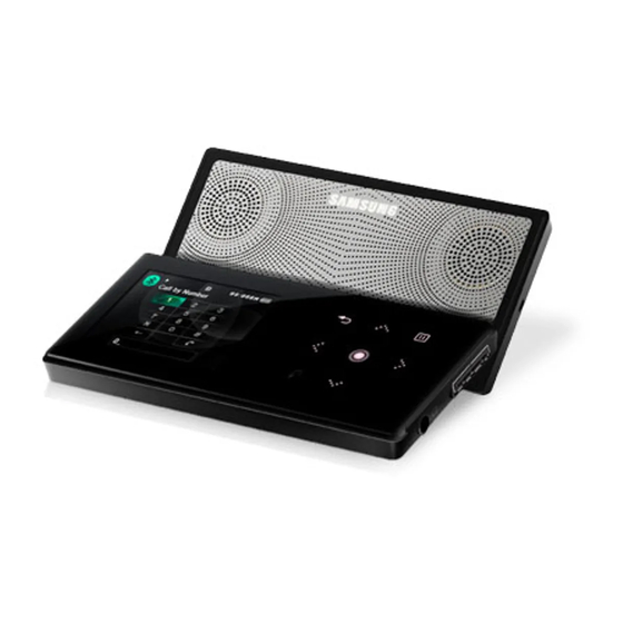
YP-S5
Refer to the service manual in the GSPN (see the rear cover) for the more information.
YEPP
Model Name : YP-S5
Model Code : YP-S5JQW/XET
Manual
1. Precaution
2. Product Specification
3. Disassembly & Reassembly
4. Troubleshooting
5. Exploded View & Part List
6. PCB Diagram
7. Schematic Diagram
CONTENTS
Advertisement
Table of Contents

Related Manuals for Samsung YP-S5


Summary of Contents for Samsung YP-S5
- Page 1 YEPP Model Name : YP-S5 Model Code : YP-S5JQW/XET SERVICE Manual YEPP CONTENTS 1. Precaution 2. Product Specification 3. Disassembly & Reassembly 4. Troubleshooting 5. Exploded View & Part List 6. PCB Diagram 7. Schematic Diagram YP-S5 Refer to the service manual in the GSPN (see the rear cover) for the more information.
- Page 2 Asia asia.samsungportal.com Mideast & Africa mea.samsungportal.com © Samsung Electronics Co.,Ltd. Nov. 2007 This Service Manual is a property of Samsung Electronics Printed in Korea Co.,Ltd. Any unauthorized use of Manual can be punished under applicable International and/or domestic law.
-
Page 3: Table Of Contents
Contents 1. Precaution 1-1 Safety Precautions ................... 1-1 1-2 Static Electricity Precautions ................1-2 2. Product Specification 2-1 Product Feature ....................2-1 2-2 Specifications ....................2-2 2-3 Specifications Analysis ..................2-3 2-4 Accessories ......................2-5 3. Disassembly & Reassembly 3-1 Disassembly Method ..................3-1 3-2 Reassembly Method ..................3-6 4. - Page 4 Contents 7. Schematic Diagram 7-1 Overall Block Diagram ..................7-2 7-2 S5L8700A02 ....................7-3 7-3 MEMORY ......................7-4 7-4 LCD/KEY/LED ....................7-5 7-5 USB/MODE/DET ....................7-6 7-6 AUDIO (EAR JACK) ..................7-7 7-7 POWER......................7-8 7-8 FM/RTC ......................7-9 7-9 CODEC ......................7-10 7-10 JTAG & Boot ....................7-11...
-
Page 5: Precaution
5. You should not put any object or liquid into product. Otherwise, it may cause failure or mal-operation. 6. If replacement material is required, service engineer should use materials with the same standard. The use of non-standardized materials may cause failure of product. Samsung Electronics... -
Page 6: Static Electricity Precautions
4. Minimize physical operation when handling with the ESD device for replacement without packing (Otherwise, namely friction between cloth fibers or lifting of the foot from the carpet floor may cause static electricity enough to damage the ESD device). Samsung Electronics... -
Page 7: Product Specification
- Hands Free (Wireless) + Conference Call - Call Recording feature External Speaker feature - Use as an external speaker for you PC → Useful for businessmen when giving presentations - Use as an external speaker for a common music device Samsung Electronics... -
Page 8: Specifications
Product Specification 2-2 Specifications Basic Specification YP-S5 Model Name Capacity Color Black White Voltage 600 mAh / DC 3.7V Dimensions (WxDxH) / Weight 47.5 x 98 x 18.1 mm / 106g Case Magnesium Noise Ratio 90dB with 20KHz LPF (based on 1KHz 0dB) Earphone Output 20mW (16Ω) -
Page 9: Specifications Analysis
Product Specification 2-3 Specifications Analysis Model Name YP-S5 YP-K5 Photo Storage TYPE Flash memory (MLC) Flash memory (MLC) SIZE : 1.8” 262K QCIF TFT LCD Display Color : 262K LCD (Real color 65K color) 1.71” Full Color OLED Resolution : 176(H) X 220(V) - Page 10 Product Specification Quality Bitrate Value Data 44 kbps 64 kbps 80 kbps 96 kbps 112 kbps 128 kbps 160 kbps 192 kbps 224 kbps 256 kbps 320 kbps 500 kbps Samsung Electronics...
-
Page 11: Accessories
Product Specification 2-4 Accessories 2-4-1 Supplied Accessories Accessories Item Item code Remark White AH59-01885A Earphones AH39-00899A USB Cable Samsung Service center AH39-00900A Audio in Cable AH46-00051A Program Installation CD Samsung Electronics... - Page 12 MEMO Samsung Electronics...
-
Page 13: Disassembly & Reassembly
Be careful not to scratch the WINDOW-LCD as you remove it. FPC-TOUCH 1) Remove the FPC-TOUCH from the connector of the TOUCH-PAD. When removing the FPC-TOUCH, be sure to use a pair of tweezers to avoid a tear. Samsung Electronics... - Page 14 : CH(0.5),*,-,M1.7,L4,ZPC(BLK),S 2) Use a pair of tweezers to push the FRAME-A from lower to up to remove 3) Remove the FRAME-A. MAIN 1) Remove the Connectors connected BOARD to the MAIN BOARD. 2) Remove the MAIN BOARD. Samsung Electronics...
- Page 15 ASSY 1) Use a pair of tweezers to remove CABINET-B the two (2) Cover-Screws from the CABINET-B. : YP-S5,ABS,T1.0,-,-,-,-,BLK,- 2) Use a pair of tweezers to lift and remove the COVER-SPEAKER. 3) Remove the four (4) ASS’Y-HINGE screws. : PH,+,M1.7,L3.0,ZPC(BLK)
- Page 16 2) Use a pair of tweezers to push the CABINET-C from left to right to remove it. FPC- 1) Remove the ASS’Y FPC-BATTERY BATTERY from the CABINET-C. Do not remove the BATTERY and the FPCB. Do not remove the BATTERY and the SPEAKER. Samsung Electronics...
- Page 17 Disassembly & Reassembly Part Name Description Description Photo ASSY 1) Remove the four (4) retention screws CABINET-B on the CABINET-B. : PH,+,M1.7,L3.0,ZPC(BLK) 2) Appearance following the completion of SET disassembly Samsung Electronics...
-
Page 18: Reassembly Method
Disassembly & Reassembly 3-2 Reassembly Method Part Name Description Description Photo WINDOW 1) Remove the pasted paper of window and attach window to FRAME-A. COVER-SPK 1) Remove the pasted paper of window and insert COVER-SPK to CABINET-C. Samsung Electronics... -
Page 19: Troubleshooting
Troubleshooting 4. Troubleshooting 4-1 Checkpoints by Error Mode ..............4-2 4-2 Upgrade Methods .................4-17 Samsung Electronics... -
Page 20: Checkpoints By Error Mode
Refer to wave pattern and Table 4-1-2. image of Table 4-1-1 and Table 4-1-2. Check BATTERY power. Does the CLOCK occur? (TP602, TP603) Defective Check power at the BATTERY (single part). Completion Recheck power after replacing the BATTERY. Samsung Electronics... - Page 21 Troubleshooting Test Point CLOCK CHECK [X-TAL101 32.768KHz], S/W100 RESET Result Check for HIGH input - DC/DC CON ENABLE S5L8700A02 Page, 7-3 S5L8700A02 Page, 7-3 POWER Page, 7-8 L602 L603 <Table 4-1-1> Samsung Electronics...
- Page 22 Troubleshooting IC601 IC702 IC103 IC700 IC800 CON400 IC501 PCB Bottom Page, 6-4 PCB Top Page, 6-2 <Table 4-1-2> Samsung Electronics...
- Page 23 Are there skips and image of Table 4-2. noises? Are the skips and noises even when playing another file? Does the same symptom persist even after upgrading the firmware to the latest version? Replace the BOARD (needs thorough examination). Completion Samsung Electronics...
- Page 24 Troubleshooting Test Point Check the LDO power. Result Check if 1.8V is output. AUDIO(EAR JACK) Page, 7-7 IC601 IC400 IC501 PCB Top Page, 6-2 <Table 4-2> Samsung Electronics...
- Page 25 Retry after upgrading to the Does Recording time latest firmware. progress normally? Do Recording files Did IC802 become Enable? play normally? Refer to wave pattern image of Table 4-3. Completion Recheck after replacing the MIC. Recheck after reordering Samsung Electronics...
- Page 26 Troubleshooting Test Point IC802, X-TAL800 Result Check for HIGH input - IC802 ENABLE IC201 IC200 IC601 CODEC Page, 7-10 IC400 IC501 IC702 IC103 IC700 IC800 PCB Bottom Page, 6-4 PCB Top Page, 6-2 <Table 4-3> Samsung Electronics CON400...
- Page 27 Do touch keys respond? If the TOUCH is poor, replace the TOUCH PAD. Replace the BOARD Is the TOUCH PAD malfunctioning? (needs thorough examination). Disassemble the unit and check if the TOUCH PAD has come off the framework. Samsung Electronics...
- Page 28 Does IC700 RTC work? Is there 32.768 KHz CLOCK? Refer to wave pattern image of Table 4-4. Replace the IC. Recheck after reordering. Does I2C work properly? Refer to wave pattern image of Table 4-4. Completion 4-10 Samsung Electronics...
- Page 29 IC201 IC200 Troubleshooting Test Point FM CLOCK CHECK Result Check if 32.768 KHz is being inputted. FM/RTC Page, 7-9 IC702 IC103 IC700 IC800 CON400 PCB Bottom Page, 6-4 <Table 4-4> Samsung Electronics 4-11...
- Page 30 MP3 Completion the latest firmware? files be played? Does it work after Did IC300 2PIN replacing the LCD? become Enable? Refer to wave pattern image of Table 4-5. Completion Replace the BOARD (needs thorough examination). 4-12 Samsung Electronics...
- Page 31 Troubleshooting Test Point IC300 2PIN LED ENABLE CHECK Result Check for HIGH input - LED ON LCD/KEY/LED Page, 7-5 IC300 IC201 IC200 PCB Bottom Page, 6-4 <Table 4-5> Samsung Electronics 4-13...
- Page 32 Refer to wave pattern image of Table 4-6. Recheck after replacing the Check power at the BATTERY BATTERY. (single part). Refer to wave pattern image of Table 4-6. Replace the BOARD Completion (needs thorough examination). 4-14 Samsung Electronics...
- Page 33 Troubleshooting Test Point IC601 12PIN Result Check for HIGH input - DC/DC CON ENABL POWER Page, 7-8 IC601 IC400 PCB Top Page, 6-2 <Table 4-6> IC501 Samsung Electronics 4-15...
- Page 34 Does the unit show in “Unknown Device” show and BOOT Update be “My Computer” as a in Device Manager? performed with DFU? removable storage? Recheck after installing the driver. Can formatting be Is it accessible? Defective done in Explorer? Completion 4-16 Samsung Electronics...
-
Page 35: Upgrade Methods
2. Check the contents of the folder that was decompressed. 3. Connect the YP-S5 to the PC. 4. Open the Removable Disk folder of the YP-S5. 5. Select the installation file in the folder that was decompressed, and then copy the upgrade files to the Removable Disk folder of the YP-S5. - Page 36 2. You need to make a USB connection, and then install the device. - After the initial installation, it will be connected automatically next time you connect. Specify the folder in which DFU is stored. [Bluesdfu_vid419_pid0145.inf Once the device is recognized, it will be connected to USB DFU DEVICE. 4-18 Samsung Electronics...
- Page 37 3. Execute the Bluesdfu.exe file in the DFU folder to launch the DFU program. 1 Select UpdateNAND.bin 2 Select Bootloader_V0.51 3 Run Download If the Browse button is not active, the DFU connection has not been made. You need to disconnect the USB cable and retry. Samsung Electronics 4-19...
- Page 38 When do you perform this procedure?: When NAND data is corrupted and after the DFU Update How to download a MAC address 1. Disassemble the YP-S5 case and check the MAC Address sticker inside. 2. Enter the following MAC Address in a blank text file and save it with the name shown below.
-
Page 39: Exploded View & Part List
Exploded View & Part List 5. Exploded View & Part List 5-1 Exploded View ..................5-2 5-2 Electrical Part List ................5-4 Samsung Electronics This Document can not be used without Samsung’s authorization. -
Page 40: Exploded View
Exploded View & Part List 5-1 Exploded View AG085 AK290 AA002 AC300 AA135 AF001 AA003 AC357 AL197 AA250 AS079 AW120 AC401 AC003 AC304 AC004 AC402 AA004 This Document can not be used without Samsung’s authorization. Samsung Electronics... - Page 41 AH97-02356A ASSY SUB MATERIAL;MOLEX,YP-S5 KEY FPCB AH07-00211A LCD;TS-180T-008A,YP-S5,-,34x47.8,2 PCB MAIN AH92-02780A ASSY PCB;YP-S5BQ_MAIN,MLC 2GB,RDS,Bluet SPEAKER 3001-002193 SPEAKER;1W,8ohm,74dB,-,11x5 TOUCH PAD AH97-01706B ASSY-TOUCH PAD ASSY;TOUCH PAD ASSY,YP-K3 6001-001292 SCREW-MACHINE;PH,+,M1.7,L3.0,ZPC(BLK),SW 6001-001691 SCREW-MACHINE;CH,+,M1.7,L4,ZPC(BLK),SWRC Samsung Electronics This Document can not be used without Samsung’s authorization.
-
Page 42: Electrical Part List
2203-000233 C-CER,CHIP;0.1nF,5%,50V,C0G,1005 C309 2203-005015 C-CER,CHIP;150nF,+80-20%,16V,Y5V,16 C714 2203-005383 C-CER,CHIP;0.0070nF,0.1pF,50V,-,100 C310 2203-005015 C-CER,CHIP;150nF,+80-20%,16V,Y5V,16 C715 2203-005383 C-CER,CHIP;0.0070nF,0.1pF,50V,-,100 C311 2203-005015 C-CER,CHIP;150nF,+80-20%,16V,Y5V,16 C312 2203-006093 C-CER,CHIP;1000nF,+80-20%,6.3V,Y5V, C716 2203-000233 C-CER,CHIP;0.1nF,5%,50V,C0G,1005 C800 2203-005900 C-CER,CHIP;1000NF,+80-20%,10V,Y5V,1 C313 2203-002709 C-CER,CHIP;100nF,+80-20%,16V,Y5V,10 This Document can not be used without Samsung’s authorization. Samsung Electronics... - Page 43 1105-001672 IC-DRAM;EM48AM1684,16Mx16Bit,TFBGA, R104 2007-000170 R-CHIP;1Mohm,5%,1/16W,TP,1005 IC201 1107-001663 IC-FLASH MEMORY;K9LAG08U0M,16Gbit,2 R117 2007-007100 R-CHIP;10Mohm,5%,1/16W,TP,1005 IC300 1203-003708 IC-DC/DC CONVERTER;AAT3151,DFN,12P, R118 2007-000157 R-CHIP;47Kohm,5%,1/16W,TP,1005 IC400 0801-002800 IC-CMOS LOGIC;7SV08,AND GATE,SC-70, R119 2007-000140 R-CHIP;1Kohm,5%,1/16W,TP,1005 IC401 1009-001018 IC-HALL EFFECT S/W;HED52XXU11,-,3P, R120 2007-000140 R-CHIP;1Kohm,5%,1/16W,TP,1005 Samsung Electronics This Document can not be used without Samsung’s authorization.
- Page 44 2007-000139 R-CHIP;220ohm,5%,1/16W,TP,1005 VAR408 1405-001093 VARISTOR;14V,20A,1x0.5x0.6mm,TP R518 2007-000139 R-CHIP;220ohm,5%,1/16W,TP,1005 VAR500 1405-001093 VARISTOR;14V,20A,1x0.5x0.6mm,TP R519 2007-000143 R-CHIP;4.7Kohm,5%,1/16W,TP,1005 VAR501 1405-001093 VARISTOR;14V,20A,1x0.5x0.6mm,TP XTAL100 2801-000102 CRYSTAL-SMD;12MHz,30ppm,-,12pF,100o R520 2007-000143 R-CHIP;4.7Kohm,5%,1/16W,TP,1005 XTAL101 2801-004339 CRYSTAL-SMD;0.032768MHZ,20PPM,SMD,9 R521 2007-000162 R-CHIP;100Kohm,5%,1/16W,TP,1005 This Document can not be used without Samsung’s authorization. Samsung Electronics...
- Page 45 AH68-02027C MANUAL-QG;YP-S5,XEF/XET,ENG/I/S/F/G AH68-40042D MARK RECYCLE;ALL,GER,-,-,ART,-,W145 AH68-40042F CARD WARRANTY;ALL,SPN,-,-,ART,-,W14 AH68-40042G CARD WARRANTY;ALL,NL,-,-,ART,-,W145 AH68-40042H CARD WARRANTY;ALL,ITA,ART,-,L210,-, AH68-40042J CARD WARRANTY;ALL,POR,ART,-,L210,-, AH69-02072A PACKING CASE-BOTTOM;YP-P2,PC,CLEAR, AH69-02074A PACKING CASE-TOP;YP-P2,PC,CLEAR,T1. AH97-02495A ASSY-PACKING MIDDLE;ASSY,YP-S5,- AH68-00508U LABEL SERIAL;COMMON,ELS,-,-,90,-,-, 0.1 SNA AH68-00701J LABEL SERIAL;YP-W3,-,-,-,-,-,-,-,-, 1.05 SNA AH68-01453A LABEL-LISTENING;YEPP EU ELS1,-,PASC AH68-50119B LABEL-EAN(B);ART-PAPER,T0.05,L29,W4 1.05 SNA AH69-02091A MASTER CARTON;YP-P2/T10,OTHER,T6,W1 0.1 SA Samsung Electronics This Document can not be used without Samsung’s authorization.
- Page 46 MEMO Samsung Electronics...
-
Page 47: Pcb Diagram
PCB Diagram 6. PCB Diagram 6-1 PCB Top ......................6-2 6-2 PCB Bottom ...................... 6-4 Samsung Electronics... -
Page 48: Pcb Top
PCB Diagram 6-1 PCB Top TP10 IC601 IC400 IC501 LCD sticking face BLUETOOTH ANTENA FM Tuner USB Connector KEY FPCB Connector BATTERY Connector Samsung Electronics... - Page 49 VCC [IO 2.8V] ADAPTOR INPUT T_ACK ADAPTOR INPUT T_DATA T_CLOCK 2.8VDD 2.8VDD LINE OUT MUTE GROUND UART RX UART TX USB D+ USB POWER LINE OUT R LINE OUT L GROUND BATTERY INPUT BATTERY INPUT EXTERNAL BATTERY DETECT PBA_CE TP10 Samsung Electronics...
-
Page 50: Pcb Bottom
PCB Diagram 6-2 PCB Bottom IC300 IC201 IC200 LCD Connector [31 PIN] IC702 IC103 SDRAM 32MB IC700 MAIN DSP IC800 24MHz USB Clock EARPHONE JACK [3 PIN] CODEC CON400 32.768KHz System Clock BLUETOOTH Module NAND Samsung Electronics... - Page 51 LCD DATA [6] LCD DATA [7] GROUND LCD DATA [8] LCD DATA [9] LCD DATA [10] LCD DATA [11] LCD DATA [12] LCD DATA [13] LCD DATA [14] LCD DATA [15] LCD RESET GROUND VCC [2.8V] VCC [2.8V] GROUND Samsung Electronics...
- Page 52 MEMO Samsung Electronics...
-
Page 53: Schematic Diagram
7-2 S5L8700A02 ...................... 7-3 7-3 MEMORY ......................7-4 7-4 LCD/KEY/LED ....................7-5 7-5 USB/MODE/DET ....................7-6 7-6 AUDIO (EAR JACK) ..................7-7 7-7 POWER ......................7-8 7-8 FM/RTC ......................7-9 7-9 CODEC ......................7-10 7-10 JTAG & Boot ..................... 7-11 Samsung Electronics This Document can not be used without Samsung’s authorization. -
Page 54: Overall Block Diagram
- 256kb SRAM Line-Out Earphone CODEC HALL IC Speaker (WM1800G) (HED52XXU11) VCC_2.8 Line In Line Out Reset Power On 32.768KHz FM Tuner ECHO /12Mhz S-35392A (Si4702) (FM2010) USB 5V This Document can not be used without Samsung’s authorization. Samsung Electronics... -
Page 55: S5L8700A02
Schematic Diagram 7-2 S5L8700A02 POWER AUDIO Samsung Electronics This Document can not be used without Samsung’s authorization. -
Page 56: Memory
Schematic Diagram 7-3 MEMORY POWER This Document can not be used without Samsung’s authorization. Samsung Electronics... -
Page 57: Lcd/Key/Led
Schematic Diagram 7-4 LCD/KEY/LED POWER AUDIO Samsung Electronics This Document can not be used without Samsung’s authorization. -
Page 58: Usb/Mode/Det
Schematic Diagram 7-5 USB/MODE/DET POWER This Document can not be used without Samsung’s authorization. Samsung Electronics... -
Page 59: Audio (Ear Jack)
Schematic Diagram 7-6 AUDIO (EAR JACK) POWER AUDIO Samsung Electronics This Document can not be used without Samsung’s authorization. -
Page 60: Power
Schematic Diagram 7-7 POWER POWER TP10 TP10 This Document can not be used without Samsung’s authorization. Samsung Electronics... -
Page 61: Fm/Rtc
Schematic Diagram 7-8 FM/RTC POWER Samsung Electronics This Document can not be used without Samsung’s authorization. -
Page 62: Codec
Schematic Diagram 7-9 CODEC POWER AUDIO 7-10 This Document can not be used without Samsung’s authorization. Samsung Electronics... -
Page 63: Jtag & Boot
Schematic Diagram 7-10 JTAG & Boot POWER Samsung Electronics This Document can not be used without Samsung’s authorization. 7-11... - Page 64 MEMO 7-12 Samsung Electronics...
Need help?
Do you have a question about the YP-S5 and is the answer not in the manual?
Questions and answers