Table of Contents
Advertisement
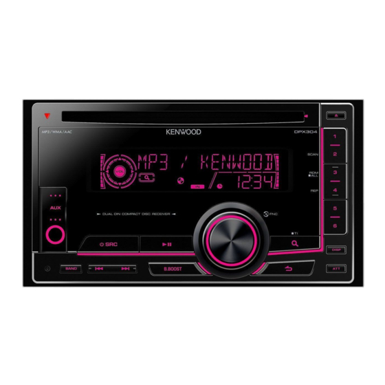
2DIN CD RECEIVER
DPX304/308U/404U
DPX-MP3120/U5120/U5120S
SERVICE MANUAL
Illustrations is DPX308U
DPX304
DC cord
DPX404U
(E30-6940-05)
DPX308U
Escutcheon
(B07-3172-12)
DPX-MP3120
Escutcheon
(B07-3025-02)
DPX-U5120
DPX-U5120S
Installation caution
X34- R44 (RS14KB3DR22J)
Compact disc (Manual)
(W01-1794-05)
Adhesive double-
coated tape
(H30-0595-04)
DC cord
(E30-6939-05)
3.5mm PRE CUT
© 2011-5 PRINTED IN JA PAN
B53-0860-00 ( N ) 303
Escutcheon
(B07-3165-02)
Mounting hardware assy
(J22-0429-13)
Remote controller assy
(A70-2104-05)
RC-405
This product uses Lead Free solder.
RoHS
This product complies with the
Lever
(D10-7012-04) x2
Screw set
(N99-1779-15)
PbF
directive for the European market.
Advertisement
Table of Contents


Need help?
Do you have a question about the DPX304 and is the answer not in the manual?
Questions and answers