
Subscribe to Our Youtube Channel
Related Manuals for Toro 33513


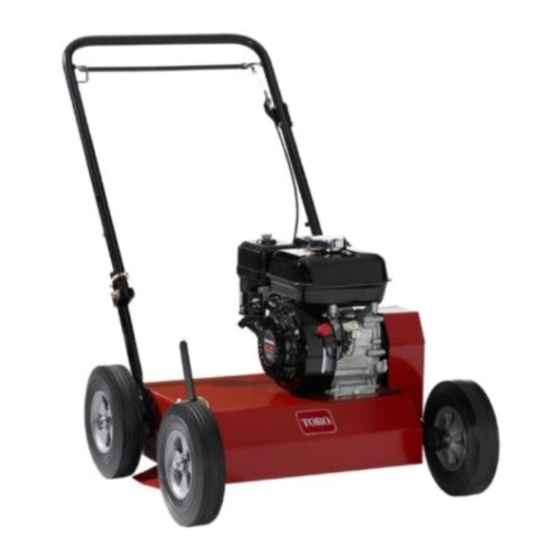
Summary of Contents for Toro 33513
- Page 1 Form No. 3398-105 Rev A 18in Dethatcher Model No. 33513—Serial No. 315000001 and Up g025335 *3398-105* A Register at www.Toro.com. Original Instructions (EN)
- Page 2 You are responsible for operating the Figure 2 product properly and safely. 1. Safety alert symbol You may contact Toro directly at www.Toro.com for product and accessory information, help finding a dealer, or to register your product. This manual uses 2 words to highlight information.
-
Page 3: Table Of Contents
Contents Safety Improper use or maintenance by the operator or Safety ................3 owner can result in injury. To reduce the potential Safe Operating Practices........... 3 for injury, comply with these safety instructions and Slope Indicator ............5 always pay attention to the safety alert symbol, which Safety and Instructional Decals ......... -
Page 4: Maintenance And Storage
Use extreme care when loading or unloading the machine tightened. Replace all worn or damaged decals. into a trailer or truck. • Use only Toro-approved attachments. The warranty • Use care when approaching blind corners, shrubs, trees, may be voided if the machine is used with unapproved or other objects that may obscure vision. -
Page 5: Slope Indicator
Slope Indicator G011841 Figure 3 This page may be copied for personal use. 1. The maximum slope you can safely operate the machine on is 20 degrees. Use the slope chart to determine the degree of slope of hills before operating. Do not operate this machine on a slope greater than 20 degrees. Fold along the appropriate line to match the recommended slope. -
Page 6: Safety And Instructional Decals
Safety and Instructional Decals Safety decals and instructions are easily visible to the operator and are located near any area of potential danger. Replace any decal that is damaged or lost. 117-4979 93-7321 1. Warning—stay away from moving parts; keep all guards in 1. - Page 7 127-4061 1. Cutting blades 4. Hold the handle to start the engine. 2. Fast 5. Release the handle to stop the engine. 3. Slow...
-
Page 8: Setup
Setup Product Overview Unfolding the Handle 1. Raise the handle to the operating position (Figure g025337 Figure 5 1. Operator-presence bail 4. Fuel tank 2. Handle 5. Depth-control lever 3. Throttle-control lever 6. Recoil-starter handle g025336 Figure 4 Controls 2. Slide the oval locking rings down each side of the upper handle over the lower handle, locking the handle sections together (Figure... -
Page 9: Recoil Starter
Recoil Starter Pull the recoil-starter handle to start the engine (Figure Fuel Shutoff Valve Close the fuel-shutoff valve when transporting or storing the machine (Figure Choke Lever Before starting a cold engine, move the choke lever forward. After the engine starts, regulate the choke to keep the engine running smoothly. -
Page 10: Specifications
Approved attachments and accessories are available for use bends the lever. with the machine to enhance and expand its capabilities. Contact an Authorized Service Dealer or Distributor or go to www.Toro.com for a list of all approved attachments and accessories. -
Page 11: Operation
Operation Note: Determine the left and right sides of the machine from the normal operating position. Checking the Engine-Oil Level Service Interval: Before each use or daily 1. Stop the engine, disengage the flail blades, and wait for all moving parts to stop. 2. - Page 12 • Do not use gasoline containing methanol. DANGER • Do not store fuel either in the fuel tank or fuel containers In certain conditions during fueling, static over the winter unless a fuel stabilizer is used. electricity can be released, causing a spark which •...
-
Page 13: Starting And Stopping The Engine
Operating the Machine 5. Install the fuel-tank cap securely. 6. Wipe up any spilled gasoline. 1. Move the depth-control lever to the desired setting. 2. Start the engine. Starting and Stopping the 3. Push down on the handle to raise the front wheels off Engine the ground. -
Page 14: Maintenance
Maintenance Recommended Maintenance Schedule(s) Maintenance Service Maintenance Procedure Interval • Change the engine oil. After the first 25 hours • Check the engine-oil level. • Clean debris from the machine. • Inspect the air-cleaner elements. • Check the belt tension. If the engine is working but the flails seem underpowered, Before each use or daily check the belt tension •... -
Page 15: Engine Maintenance
Engine Maintenance 10. Clean the foam element in warm, soapy water or in a nonflammable solvent. 11. Rinse and dry the foam element thoroughly. Servicing the Air Cleaner 12. Dip the foam element in clean engine oil, then squeeze Service Interval: Before each use or daily—Inspect the out the excess oil. -
Page 16: Cleaning The Sediment Cup
4. Remove the drain plug (Figure 16). 3. Move the fuel-shutoff valve to the O position. 4. Remove the sediment cup and O-ring (Figure 17). G019428 Figure 16 1. Drain plug g020282 Figure 17 5. When the oil has drained completely, lower the front wheels to the ground, replace the drain plug, and 1. -
Page 17: Belt Maintenance
Belt Maintenance Checking the Belt Tension Service Interval: Before each use or daily—Check the belt tension. If the engine is working but the flails seem underpowered, check the belt tension 1. Stop the machine on a level surface, shut off the Figure 18 engine, disconnect the spark-plug wire, and raise the 1. -
Page 18: Adjusting The Belt Tension
Adjusting the Belt Tension Maintaining the Flail 1. Stop the machine on a level surface and shut off the Blades engine by releasing the operator-presence bail. 2. To tighten the belt, loosen the 4 mounting nuts Inspecting the Flail Blades securing the engine to the frame. - Page 19 Figure 21 1. Rod 3. Spacer 2. Flail 4. Cotter pin 8. Carefully add flails and spacers to rod in the same order as they were removed. Important: Align the rod with the formed head toward the center of the machine. 9.
-
Page 20: Storage
Removing the Machine from Storage Storage 1. Raise the flail blades, stop the machine, shut off the 1. Check and tighten all fasteners. engine, and disconnect the spark-plug wire. 2. Inspect the spark plug and replace it if it is dirty, worn, 2. - Page 21 Notes:...
- Page 22 Notes:...
- Page 23 Notes:...
- Page 24 Toro importer. If all other remedies fail, you may contact us at Toro Warranty Company. Australian Consumer Law: Australian customers will find details relating to the Australian Consumer Law either inside the box or at your local Toro Dealer.
Need help?
Do you have a question about the 33513 and is the answer not in the manual?
Questions and answers