Advertisement
Quick Links
Assembly Manual
=ZAGI-400=
=ELECTRIC=
Visit: www.Zagi.com Email: Zod@Zagi.com V oice: (310) 301-1614 Fax : (310) 822-7695
TRICK R/C Products LLC 938 Victoria Avenue Venice, California 90291
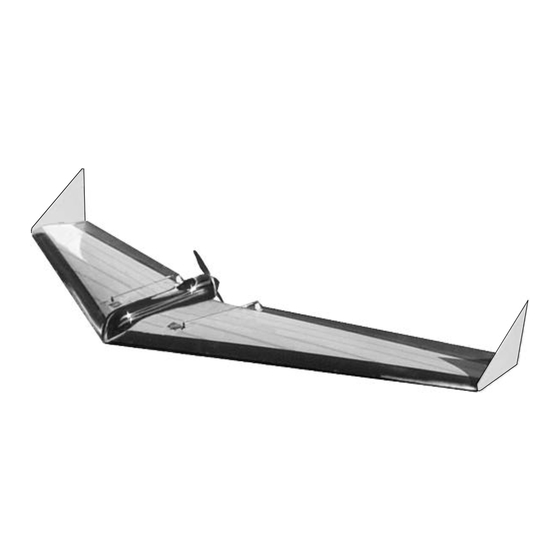
Wing Span
Wing Area
Airfoil
Weight
Loading
Radio
48"
2..833 sq. ft.
Zagi 999
19 oz.
5.7 oz/sq. ft.
3 channels w/mixer
Advertisement

Subscribe to Our Youtube Channel
Related Manuals for ZAGI 400 ELECTRIC


Summary of Contents for ZAGI 400 ELECTRIC
- Page 1 Wing Area 2..833 sq. ft. Airfoil Zagi 999 Weight 19 oz. Loading 5.7 oz/sq. ft. Radio 3 channels w/mixer Visit: www.Zagi.com Email: Zod@Zagi.com V oice: (310) 301-1614 Fax : (310) 822-7695 TRICK R/C Products LLC 938 Victoria Avenue Venice, California 90291...
- Page 2 Read the entire manual before beginning construction! The target weight for the Zagi-400 is 19 oz. The airplane is designed to balance at 8” measured back from the nose. In order to achieve these two objectives, a speed 400 motor, micro servos, and a 500 mAh 7 or 8 cell battery pack must be used.
- Page 3 Molded motor mount and battery tray Molded canopy Speed 400 motor and prop Zagi 20 Electronic Speed Control (ESC) with Battery Eliminator Circuit (BEC) 7 or 8 cell 500 mAh battery with Deans Ultra plug Tie wraps to secure motor...
- Page 4 The fiber tape schedule described in Figure 3 is intended for aerobatics and thermal applications. If the tasks for the Zagi-400 will include high-speed dives, the fiber tape must be increased to three side-by-side strips instead of only one or use 2” fiber tape. The two-inch tape I used increased the flying weight by ½...
- Page 5 4” Figure 3 (See Figure 4) Lay the wing in the top bed bottom-side up. Start the tape covering at the trailing edge (TE) of the wing by wrapping a strip of color tape around the TE being careful to follow the shape. Working from the TE forward, lay strips of tape from tip to at least 4 inches past center.
- Page 6 (See Figure 5) Hold the elevons together and sand them until they are identical. Trim the outboard end to match the angle of the wing tip. Trim the inboard end of the elevon to match the angle of the motor cut-out. Make the elevons about 1/16” shorter than the wing tip to make sure the elevons don’t rub against the winglets after they are installed.
- Page 7 (See Figure 7) The control rods may not fit in the servo control arm. The end of the control rod can be filed to fit in the servo control arm or the top hole in the servo control arms can be reamed by spinning an X-acto #11 blade in the hole or drilling with a #48 drill (.076”).
- Page 8 (See Figure 8) Position the servos on the pre-marked servo positions. Outline the exact shape. Cut or router the foam to provide a snug flush fit. Wood shims can be used to assure a tight fit. Position the receiver 6 1/4” back from the nose. Position the receiver so that the input slots align with the centerline of the wing.
- Page 9 Figure 9 (See Figure 10) The Zagi-20 ESC (Electronic Speed Control) is provided in the kit. The red and black pair of wires with the red male Deans Ultra connector plugs into the battery. The red and blue pair of wires with the separate spade connectors plug into the motor.
- Page 10 RECEIVER RED DEANS ULTRA PLUG RIBBON WIRE FROM ESC TO RECEIVER RED WIRE WIRE TIE Figure 11 (See Figure 11) Attach the motor to the tray with a tie wrap. Locate the dimples on the rails on either side of the motor mount. Spin an X-acto blade in the dimples to make a hole.
- Page 11 (See Figure 12) Align the motor tray with the nose. Make sure that the motor tray is centered over the center line at the trailing edge. Attach the motor tray with a strip of fiber tape on each side. Cover the servos with strips of color tape. (See Figure 12) Peel the protective paper off of the hook side of two 1”...
- Page 12 (See Figure 13) Punch-out and separate the two nested clear winglets. Punch-out the 1 1/4" x 1/4" slot in the winglet. (See Figure 14) Put a piece of fiber filament tape through the slot to the top of the wing and wrap it around to the bottom of the wing.
- Page 13 (See Figure 15) Lay wing bottom-side-up. Using a square, mark the CG by making a line perpendicular to the center line 8" back from the nose on both panels. Tape a 1/4” dowel directly over the CG line. A round pencil or ball-point pen can be used.
- Page 14 First time motor power-up The following steps are provided for a safe first time power-up of the motor. Do not press the prop onto the motor shaft yet. Test the motor hook-up before the prop is in- stalled. Make sure that the battery is charged. The batteries are not shipped with a charge.
-
Page 15: First Flight
Zagi-400 securely by the nose. Move the throttle stick to the half throttle position momen- tarily. The first glide test should be done on flat land in a light breeze. The Zagi-400 should be held by the nose with your palm up over your head and your thumb wrapped around to the top. - Page 16 Throwing the Zagi-400 Figure 17 Hold the Zagi-400 by the nose with your palm up over your head and your thumb wrapped around to the top. The secret to this launch is the energy you exert with your fingers in the follow through.
- Page 17 Zagi is a registerd trademark of Trick R/C Products LLC...
Need help?
Do you have a question about the 400 ELECTRIC and is the answer not in the manual?
Questions and answers