Table of Contents
Advertisement
Quick Links
Advertisement
Table of Contents

Related Manuals for Toro 03708N


Summary of Contents for Toro 03708N
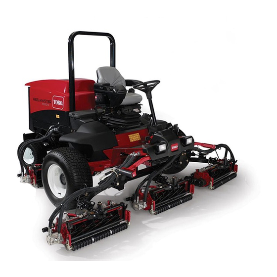
- Page 1 Form No. 3374-295 Rev C Reelmaster ® 7000-D 4-Wheel Drive Traction Unit Model No. 03708N—Serial No. 313000001 and Up To register your product or download an Operator's Manual or Parts Catalog at no charge, go to www.Toro.com. Original Instructions (EN)
-
Page 2: Introduction
Genuine Toro spark arresters are approved by the USDA Forestry Service. Important: This engine is equipped with a spark arrester muffler. -
Page 3: Table Of Contents
Fuel Pick up Tube Screen........40 Safe Operating Practices ........4 Bleeding Air from the Injectors......41 Toro Riding Mower Safety ........6 Electrical System Maintenance........ 41 Safety and Instructional Decals ......7 Charging and Connecting the Battery ....41 Setup ................. -
Page 4: Safety
Preparation Safety • While mowing, always wear substantial footwear, This machine meets or exceeds ANSI B71.4-2004 long trousers, hard hat, safety glasses, and ear specifications in effect at the time of production. protection. Long hair, loose clothing, or jewelry may get tangled in moving parts. -
Page 5: Maintenance And Storage
– Do not turn sharply. Use care when reversing. • Do not operate the mower under the influence of alcohol or drugs. – Use counterweight(s) or wheel weights when suggested in the operator's manual. • Lightning can cause severe injury or death. If lightning is seen or thunder is heard in the area, do •... -
Page 6: Toro Riding Mower Safety
The following list contains safety information specific Cutting units must be lowered when going down to Toro products or other safety information that you slopes to maintain steering control must know that is not included in the CEN, ISO, or •... -
Page 7: Safety And Instructional Decals
• If major repairs are ever needed or if assistance is desired, contact an Authorized Toro Distributor. • Use only Toro-approved attachments and replacement parts. The warranty may be voided if used with unapproved attachments. Safety and Instructional Decals Safety decals and instructions are easily visible to the operator and are located near any area of potential danger. - Page 8 98-4387 1. Warning—wear hearing protection. 119-3905 1. Reel speed 93-6688 1. Warning—read the 2. Cutting hazard of hand or instructions before foot—stop the engine and servicing or performing wait for moving parts to maintenance. stop. 117-4765 1. Read the Operator's Manual. 2.
- Page 9 120-1683 1. Warning—read the Operator's Manual, do not operate this 4. Warning—do not park the machine on slopes; engage the machine unless you are trained. parking brake, lower the cutting units, stop the engine and remove the ignition key before leaving the machine. 2.
- Page 10 Battery Symbols Some or all of these symbols are on your battery 1. Explosion hazard 6. Keep bystanders a safe distance from the battery. 2. No fire, open flame, or 7. Wear eye protection; smoking. explosive gases can cause blindness and other injuries 3.
-
Page 11: Setup
Setup Loose Parts Use the chart below to verify that all parts have been shipped. Procedure Description Qty. – No parts required Adjust the support rollers Front hose guide-R.H. Install the cutting units Front hose guide-L.H. – No parts required Adjust the turf compensation spring. -
Page 12: Adjusting The Support Rollers
2. Remove the shipping brackets and discard. 3. Remove the cutting units from the cartons. Assemble and adjust as described in the cutting unit Operator's Manual. Adjusting the Support Rollers 4. Make sure the counter weight (Figure 4) is installed to the proper end of the cutting unit as described in No Parts Required the cutting unit Operator's Manual. - Page 13 nut. The bolt head is to be positioned to the outer side of the tab as shown in Figure 6. Figure 7 Figure 6 1. Opposite carrier frame tab 2. Rod bracket D. Mount the rod bracket to the cutting unit tabs with the carriage bolts and nuts (Figure 6).
- Page 14 Note: 32 inch cutting units are not equipped with pivot spacers. G015978 Figure 10 1. Hex socket screw 3. Carrier frame 2. Pivot spacer 4. Flange lock nut G015976 7. Lower all the lift arms completely. Figure 11 8. Coat the carrier frame shaft with clean grease 1.
-
Page 15: Adjusting The Turf Compensation Spring
A. Remove the lynch pin and washer securing the lift arm pivot shaft to the lift arm and slide the lift arm pivot shaft out of the lift arm (Figure 13). Figure 13 1. Lift arm pivot shaft lynch pin and washer B. -
Page 16: Using The Cutting Unit Kickstand
Figure 16 1. Turf compensation spring 3. Spring rod 2. Hair pin cotter 4. Hex nuts Figure 17 1. Cutting unit kickstand 2. Tighten the hex nuts on the front end of the spring rod until the compressed length of the spring is 6.25 inches (15.9 cm) (Figure 16). -
Page 17: Greasing The Machine
Product Overview Controls Greasing the Machine Brake Pedals Two foot pedals (Figure 19) operate individual wheel No Parts Required brakes for turning assistance and to aid in obtaining better side hill traction. Procedure Pedal Locking Latch Before the machine is operated, it must be greased to ensure proper lubrication. -
Page 18: Key Switch
Charge Indicator toward you to the most comfortable position and then release the pedal. The charge indicator (Figure 21) illuminates when the system charging circuit malfunctions. Mow Speed Limiter Key Switch When the mow speed limiter (Figure 20) is flipped up it will control the mow speed and allow the cutting units The key switch (Figure 21) has three positions: Off, to be engaged. -
Page 19: Throttle Control
the machine, with the cutting units in the down position, has two positions R (manual reverse) and Auto (normal). press the lift switch down to allow the cutting units to Refer to Engine Cooling Fan Operation in the Operation float and mow. Section of manual. -
Page 20: Fuel Gauge
Weight gauge Indicates when the seat is adjusted to the weight of the operator (Figure 26). Height adjustment is made by positioning the suspension within the range of the green region. Figure 24 1. Reel speed controls Fuel Gauge Figure 26 1. -
Page 21: Specifications
A selection of Toro approved attachments and accessories is available for use with the machine to enhance and expand its capabilities. Contact your Authorized Service Dealer or Distributor or go to www.Toro.com for a list of all approved attachments and accessories. -
Page 22: Operation
• Preferred oil: SAE 15W-40 (above 0°F) • Alternate oil: SAE 10W-30 or 5W-30 (all temperatures) Figure 28 Note: Toro Premium Engine oil is available from your distributor in either 15W-40 or 10W-30 1. Dipstick viscosity. See the parts catalog for part numbers. -
Page 23: Checking The Cooling System
Figure 29 1. Oil fill cap Note: When using different oil, drain all old oil from the crankcase before adding new oil. Figure 30 5. Install the oil fill cap and dipstick. 1. Expansion tank 6. Close the hood and secure it with the latches. 2. - Page 24 WARNING DANGER Fuel is harmful or fatal if swallowed. Long-term In certain conditions, fuel is extremely flammable exposure to vapors can cause serious injury and and highly explosive. A fire or explosion from fuel illness. can burn you and others and can damage property. •...
-
Page 25: Checking The Hydraulic Fluid Level
(Available in 5 gallon pails or 55 gallon drums. See parts catalog or Toro distributor for part numbers.) Alternate fluids: If the Toro fluid is not available, other fluids may be used provided they meet all the following material properties and industry specifications. We do not recommend the use of synthetic fluid. -
Page 26: Checking The Tire Pressure
3. Remove the dipstick from the filler neck and wipe When the temperature is less than 20°F (-7°C), the it with a clean rag. Insert the dipstick into the filler starter motor can be run for 30 seconds on then 60 neck;... -
Page 27: Setting The Reel Speed
pedal is released, it is strongly recommended that the neutral position. The engine should kill. If the engine be stopped before rising from the seat. engine does not kill, there is a malfunction in the interlock system that should be corrected before To check the operation of the interlock switches, beginning operation. -
Page 28: Adjusting The Lift Arm Counterbalance
Figure 35 1. Spring 2. Spring actuator 4. Move the spring actuator to the desired hole Figure 34 location and secure with locknut. 1. Reel speed control knob 5. Repeat the procedure on the remaining spring. Adjusting the Lift Arm Turn Adjusting the Lift Arm Around Position Counterbalance... -
Page 29: Pushing Or Towing The Machine
Jacking Points turn around height or move the switch down to decrease the lift arm turn around height. Tighten • On the front of the machine on the frame on the the mounting screws. inside of each drive tire • On the rear of the machine at the center of the axle Pushing or Towing the Machine Tie Downs... -
Page 30: Diagnostic Ace Display
Verifying the Interlock Switch Function If the diagnostic light is not illuminated when the key switch is in the On position, this indicates that the 1. Park the machine on a level surface, lower the electronic controller is not operating. Possible causes cutting units, stop the engine, and engage the are as follows: parking brake. -
Page 31: Operating Characteristics
ECM problem. If the switch and/or check the switches with an ohm this occurs, contact your Toro Distributor for assistance. meter. Replace any defective switches and repair Important: The Diagnostic ACE display must any defective wiring. -
Page 32: Engine Cooling Fan Operation
Warning System brakes can be used to assist in turning the machine. However, use them carefully, especially on soft or If a warning light comes on during operation, stop the wet grass because the turf may be torn accidentally. machine immediately and correct the problem before Another benefit of the brakes is to maintain traction. -
Page 33: Maintenance
Maintenance Note: Determine the left and right sides of the machine from the normal operating position. Recommended Maintenance Schedule(s) Maintenance Service Maintenance Procedure Interval • Torque the wheel nuts. After the first 8 hours • Change the engine oil and filter. After the first 50 hours •... -
Page 34: Daily Maintenance Checklist
Daily Maintenance Checklist Duplicate this page for routine use. Maintenance For the week of: Check Item Mon. Tues. Wed. Thurs. Fri. Sat. Sun. Check the safety interlock operation Check the brake operation Check the engine oil and fuel level Check the cooling system fluid level Drain the water/fuel... -
Page 35: Service Interval Chart
Service Interval Chart Figure 41 CAUTION If you leave the key in the ignition switch, someone could accidently start the engine and seriously injure you or other bystanders. Remove the key from the ignition before you do any maintenance. -
Page 36: Premaintenance Procedures
Premaintenance Lubrication Procedures Greasing the Bearings and Bushings Removing the Hood Service Interval: Every 50 hours 1. Release hood latches (Figure 42) and pivot open the hood. The machine has grease fittings that must be lubricated regularly with No. 2 General Purpose Lithium Base Grease. - Page 37 • Steering cylinder ball joints (2) (Figure 45) • Cutting unit carrier frame (2 per cutting unit) (Figure 47) • Cutting unit lift arm pivot (1 per cutting unit) (Figure 47) Figure 47 Figure 45 1. Top fitting on king pin •...
-
Page 38: Engine Maintenance
Engine Maintenance which could force dirt through the filter into the intake tract. This cleaning process prevents debris from migrating Servicing the Air Cleaner into the intake when the primary filter is removed. Service Interval: Every 400 hours 3. Remove and replace the primary filter (Figure 50). Check the air cleaner body for damage which could Cleaning of the used element is not recommended cause an air leak. -
Page 39: Servicing The Engine Oil And Filter
Servicing the Engine Oil and Adjusting the Throttle Filter Adjust the throttle cable (Figure 54) so that the governor lever on the engine contacts the high speed set bolt at Service Interval: After the first 50 hours the same point that the throttle cable contacts the end of Every 400 hours the slot in the control arm. -
Page 40: Fuel System Maintenance
Servicing the Water Separator Fuel System Maintenance Service Interval: Before each use or daily—Drain water or other contaminants from fuel filter/water separator. DANGER Every 400 hours—Replace the fuel Under certain conditions, diesel fuel and fuel filter canister. vapors are highly flammable and explosive. A fire or explosion from fuel can burn you and others and Drain water or other contaminants from water separator can cause property damage. -
Page 41: Bleeding Air From The Injectors
Bleeding Air from the Injectors Electrical System Maintenance Note: This procedure should be used only if the fuel system has been purged of air through normal priming procedures and the engine will not start. Charging and Connecting the 1. Loosen the pipe connection to the No. 1 injector Battery nozzle and holder assembly at the injection pump (Figure 56). -
Page 42: Battery Care
Battery posts, terminals, and related cable connectors with Grafo 112X (skin-over) grease accessories contain lead and lead compounds, (Toro Part No. 505-47) or petroleum jelly to prevent chemicals known to the State of California corrosion. to cause cancer and reproductive harm. -
Page 43: Fuses
Fuses The fuses are located under the operators control panel. TEC-5002 7.5A 7.5A 7.5A 120-1672 Figure 59 Figure 61 1. Fuses Unhook the latch and raise the operator's console panel (Figure 60) to expose the fuses (Figure 61). Figure 60 2. -
Page 44: Drive System Maintenance
Drive System 3. If the oil level is low, remove the plug at the 12 o’clock position and add oil until it begins to flow Maintenance out of the hole at the 3 o’clock position. 4. Re-install both plugs. Checking the Torque of the 5. -
Page 45: Checking The Rear Axle Lubricant
Figure 65 1. Check plug 2. Fill plug g019743 Figure 64 1. Brake housing 2. Drain plug Changing the Rear Axle Lubricant 4. When all of the oil has drained from both locations, re-install the plug in the brake housing. Service Interval: After the first 200 hours 5. -
Page 46: Adjusting The Traction Drive For Neutral
Adjusting the Traction Drive for Neutral The machine must not creep when traction pedal is released. If it does creep, an adjustment is required. 1. Park machine on a level surface, shut engine off, position speed control into LOW range and lower cutting units to the floor. -
Page 47: Cooling System Maintenance
Cooling System Maintenance Servicing the Engine Cooling System Service Interval: Before each use or daily Remove debris from the engine area, oil cooler and radiator daily. Clean them more frequently in dirty conditions. 1. Unlatch and swing open rear screen (Figure 70). Clean the screen thoroughly of all debris. -
Page 48: Brake Maintenance
Brake Maintenance Belt Maintenance Adjusting the Service Brakes Servicing the Alternator Belt Adjust the service brakes when there is more than 1 in. Service Interval: Every 100 hours (25 mm) of “free travel" of the brake pedal, or when the Check the condition and tension of the belts (Figure 74) brakes do not work effectively. -
Page 49: Hydraulic System Maintenance
Figure 76 every 800 operating hours, in normal conditions. 1. Hydraulic filter Use Toro replacement filters Part No. 94-2621 for the rear (cutting unit) of the machine and 75-1310 for the 4. Ensure that the filter mounting area is clean. Screw front (charge) of the machine. -
Page 50: Checking The Hydraulic Lines And Hoses
Checking the Hydraulic Lines Cutting Unit Maintenance and Hoses Backlapping the Cutting Units Service Interval: Before each use or daily Inspect the hydraulic lines and hoses daily for WARNING leaks, kinked lines, loose mounting supports, wear, Contact with the reels or other moving parts can loose fittings, weather deterioration, and chemical result in personal injury. -
Page 51: Cleaning
Cleaning Servicing the Spark Arrestor Muffler Service Interval: Every 200 hours Every 200 hours operation, clear the muffler of carbon buildup. 1. Remove the pipe plug from the clean-out port at the lower side of the muffler. CAUTION The muffler may be hot and could cause injury. Be careful while working around the muffler. -
Page 52: Storage
B. Clean the battery, terminals, and posts with a wire brush and baking soda solution. C. Coat the cable terminals and battery posts with Grafo 112X skin-over grease (Toro Part No. 505-47) or petroleum jelly to prevent corrosion. D. Slowly recharge the battery every 60 days for 24... -
Page 53: Schematics
Schematics Hydraulic Schematic (Rev. A) - Page 54 Electrical Schematic-Sheet 1 (Rev. C)
- Page 55 Electrical Schematic-Sheet 2 (Rev. C)
-
Page 56: The Toro Total Coverage Guarantee
Countries Other than the United States or Canada Customers who have purchased Toro products exported from the United States or Canada should contact their Toro Distributor (Dealer) to obtain guarantee policies for your country, province, or state. If for any reason you are dissatisfied with your Distributor's service or have difficulty obtaining guarantee information, contact the Toro importer.
Need help?
Do you have a question about the 03708N and is the answer not in the manual?
Questions and answers