Table of Contents
Advertisement
Advertisement
Table of Contents

Related Manuals for Toro 03670


Summary of Contents for Toro 03670
- Page 1 Form No. 3381-780 Rev A Reelmaster ® 5010 Series Traction Unit Model No. 03670—Serial No. 314000001 and Up Model No. 03680—Serial No. 314000001 and Up Model No. 03690—Serial No. 314000001 and Up *3381-780* A Register at www.Toro.com. Original Instructions (EN)
-
Page 2: Introduction
You are responsible for operating the product properly and safely. You may contact Toro directly at www.Toro.com for product and accessory information, help finding a dealer, or to register your product. -
Page 3: Table Of Contents
Safety ................4 Fuel Pick-up Tube Screen ........46 Safe Operating Practices........... 4 Bleeding Air from the Fuel Injectors......46 Toro Riding Mower Safety ........6 Electrical System Maintenance ........47 Sound Power Level ..........7 Servicing the Battery..........47 Sound Power Level ..........7 Fuses ..............47... -
Page 4: Safety
Preparation Safety • While mowing, always wear substantial footwear, long trousers, hard hat, safety glasses, and ear protection. Long This machine meets or exceeds CEN standard EN hair, loose clothing, or jewelry may get tangled in moving 836:1997, ISO standard 5395:1990, and ANSI B71.4-2004 parts. -
Page 5: Maintenance And Storage
• • Before attempting to start the engine, disengage all blade Keep hands and feet away from the cutting units. attachment clutches, shift into neutral, and engage the • Look behind and down before backing up to be sure of parking brake. -
Page 6: Toro Riding Mower Safety
Toro Riding Mower Safety guards can lead to thrown object injuries. Do not resume mowing until the area is cleared. The following list contains safety information specific to Toro products or other safety information that you must know that Maintenance and Storage is not included in the CEN, ISO, or ANSI standard. -
Page 7: Sound Power Level
Sound Power Level Vibration Level Model 03670 and 03680 Model 03680 This unit has a guaranteed sound power level of 103 dBA, Hand-Arm which includes an Uncertainty Value (K) of 1 dBA. Measured vibration level for right hand = .37 m/s... -
Page 8: Safety And Instructional Decals
Safety and Instructional Decals Safety decals and instructions are easily visible to the operator and are located near any area of potential danger. Replace any decal that is damaged or lost. 108-5278 1. Read the Operator's Manual. 106-6754 1. Warning—do not touch the hot surface. 2. - Page 9 110-8921 110-8924 1. Traction unit speed 1. Warning—read the Operator's Manual and receive training. 2. Slow 2. Thrown object hazard—keep bystanders a safe distance from the machine. 3. Fast 3. Warning—do not park the machine on slopes; engage the parking brake, lower the cutting units, stop the engine and remove the ignition key before leaving the machine.
- Page 10 114–8891 (Use for Models 5510 & 5610 with 7 inch reel cutting units) 1. Front reels circuit controls 3. Mow and backlap 5. Height-of-cut 2. Rear reels circuit controls 4. Read the Operator's Manual. 6. Traction unit speed 114–8890 (Use for Model 5410 with 5 inch reel cutting units) 1.
- Page 11 117-0168 1. Read the Operator's Manual. Battery Symbols Some or all of these symbols are on your battery 1. Explosion hazard 6. Keep bystanders a safe distance from the battery. 7. Wear eye protection; 2. No fire, open flame, or smoking.
-
Page 12: Setup
No parts required Adjust the turf compensation spring. Rear weights (size varies with Install rear weights (order from your Varies configuration). Toro Distributor). Hood latch assembly Install the CE Hood Latch Washer Cutting unit kickstand Install the Cutting Unit Kickstand. -
Page 13: Adjusting The Step Height
Adjusting the Tire Pressure Adjusting the Control Arm Position No Parts Required No Parts Required Procedure Procedure The tires are over-inflated for shipping. Therefore, release some of the air to reduce the pressure. Correct air pressure in The control arm position can be adjusted for the operators the front and rear tires is 83 to 103 kPa (12 to 15 psi). - Page 14 2. Remove the shipping brackets and discard. 3. Remove the cutting units from the cartons. Assemble and adjust as described in the cutting unit Operator's Manual. 4. Make sure the counter weight (Figure 4) is installed to the proper end of the cutting unit as described in the cutting unit Operator's Manual.
- Page 15 g019284 Figure 9 1. Hose guides (each must lean toward the center cutting unit) Note: When installing or removing the cutting units, make sure the hairpin cotter is installed in the spring rod hole next to the rod bracket. Otherwise, the hairpin cotter must be installed in the hole in the end of the rod.
-
Page 16: Adjusting The Turf Compensation Spring
B. Insert the lift arm yoke onto the carrier frame shaft (Figure 11). C. Insert the lift arm shaft into the lift arm and secure it with the washer and lynch pin (Figure 12). 10. Insert the cap over the carrier frame shaft and lift arm yoke. - Page 17 Figure 15 1. Turf compensation spring 3. Spring rod 2. Hair pin cotter 4. Hex nuts 2. Tighten the hex nuts on the front end of the spring rod until the compressed length of the spring is 12.7 cm (5 inches) on Reelmaster 5410, 5 inch cutting units or 15.9 cm (6.25 inches) on Reelmaster 5510 &...
-
Page 18: Installing Rear Weights
ANSI B71.4-2004 Standards when equipped with rear weights and/or 90 lb of calcium chloride ballast is added to rear wheels. Use the following charts to determine the combinations of weights required for your configuration. Order parts from your local Authorized Toro Distributor. Weight P/N 110-8985-03... - Page 19 Use the following chart to determine the rear weight requirements when a 4 Post ROPS Conversion Kit is added. Weight P/N 110-8985-03 Number of Number of 2* or 4 Groomers, roller Fasteners (2 weights to weights to meet Tractor Wheel brushes, and/or each required) Weight Location...
- Page 20 Use the following chart to determine the rear weight requirements when the traction unit is also equipped with a Sunshade Canopy on a 2 Post ROPS. Weight P/N 110-8985-03 Number of Number of 2* or 4 Groomers, roller Fasteners (2 weights to weights to meet Tractor...
- Page 21 Figure 16 1. Weight 3. Nut 2. Carriage bolt On four wheel drive models, use the following procedure to mount the appropriate amount of weight (see weight charts) to the top or bottom of the rear bumper as shown in Figure 17. Figure 17 1.
-
Page 22: Installing The Ce Hood Latch
5. Inside the hood, insert the metal washer onto the latch and secure with the nut. Make sure the latch engages the frame catch when it is locked. Use the enclosed hood latch key to operate the hood latch. Installing the CE Hood Latch Parts needed for this procedure: Hood latch assembly Using the Cutting Unit... -
Page 23: Using The Gauge Bar
Figure 22 1. Gauge bar 4. Holes used for setting Groomer HOG Figure 21 2. Height adjusting screw 5. Hole not used 1. Chain bracket 3. Cutting unit kickstand 3. Nut 2. Snapper pin Using the Gauge Bar Parts needed for this procedure: Gauge bar Procedure Use the gauge bar to adjust the cutting unit. -
Page 24: Product Overview
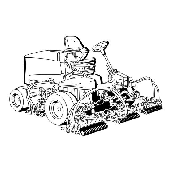
Product Overview speed, fully press the pedal while the throttle is in the Fast position. To stop, reduce foot pressure on the traction pedal and allow it to return to the center position. Figure 23 1. Engine hood 5. Seat 2. -
Page 25: Key Switch
Glow Plug Indicator Light This light (Figure 26) illuminates when the glow plugs are preheating. Engine Oil Pressure Warning Light This light (Figure 26) indicates dangerously low engine oil pressure. Charge Indicator The charge indicator (Figure 26) illuminates when the system charging circuit malfunctions. -
Page 26: Headlight Switch
Figure 28 1. Hour meter Figure 30 1. Fuel tank cap Hydraulic Filter Restriction Indicator 2. Fuel gauge With the engine running at normal operating temperature, view the indicator (Figure 29), it should be in the Green zone. When the indicator is in the Red zone, change the hydraulic Headlight Switch filters. -
Page 27: Specifications
A selection of Toro approved attachments and accessories is available for use with the machine to enhance and expand its capabilities. Contact your Authorized Service Dealer or Distributor or go to www.Toro.com for a list of all approved attachments and accessories. -
Page 28: Operation
Preferred oil: SAE 15W-40 (above 0 degrees F) • Alternate oil: SAE 10W-30 or 5W-30 (all temperatures) Toro Premium Engine oil is available from your distributor in either 15W-40 or 10W-30 viscosity. 1. Park the machine on a level surface, stop the engine, set the parking brake and remove the key from the ignition switch. -
Page 29: Checking The Cooling System
Checking the Cooling System Adding Fuel Clean debris off of the screen, oil cooler, and front of the Use only clean, fresh diesel fuel or biodiesel fuels with low radiator daily and more often if conditions are extremely dusty (<500 ppm) or ultra low (<15 ppm) sulfur content. The minimum cetane rating should be 40. -
Page 30: Checking The Hydraulic Fluid
Toro Premium All Season Hydraulic Fluid (Available in 5 gallon pails or 55 gallon drums. See parts catalog or Toro • If this is not possible, then refuel such distributor for part numbers.) - Page 31 EnviroSyn 46H Important: Mobil EAL EnviroSyn 46H is the only synthetic biodegradable fluid approved by Toro. This fluid is compatible with the elastomers used in Toro hydraulic systems and is suitable for a wide-range of temperature conditions. This fluid is compatible...
-
Page 32: Checking The Reel To Bedknife Contact
Bleeding the Fuel System You must bleed the fuel system before starting the engine if any of the following situations have occurred: • Initial start up of a new machine. • Engine has ceased running due to lack of fuel. •... -
Page 33: Starting And Stopping The Engine
preheating is required, turn key to the Off position and then to the On/Preheat position. Repeat this process as required. 4. Run the engine at low idle speed until it warms up. Stopping the Engine 1. Move all controls to Neutral, set the parking brake, move the throttle to the low idle position and allow the engine to reach low idle speed. -
Page 34: Adjusting The Lift Arm Counterbalance
Figure 41 1. Front reels circuit controls 3. Reel—mow and backlap 5. Reel—height of cut 2. Rear reels circuit controls 4. Read the Operator's Manual. 6. Machine speed Figure 42 1. Front reels circuit controls 3. Reel—mow and backlap 5. Reel—height of cut 2. -
Page 35: Adjusting The Lift Arm Turn Around Position
Adjusting the Lift Arm Turn CAUTION Around Position The springs are under tension. 1. Position the machine on a level surface, lower the Use caution when adjusting them. cutting units, stop the engine, engage the parking brakes, and remove the key from ignition switch. 2. -
Page 36: Jacking Points
Tie Downs • Front—the hole in the rectangular pad, under the axle tube, inside each front tire (Figure 47). Figure 45 1. Bypass valve 2. Close the bypass valve before starting the engine. However, do not exceed 7-11 N-m. (5-8 ft-lb) torque to close the valve. -
Page 37: Diagnostic Ace Display
Diagnostic Ace Display correctly and the key switch is moved to the On position, the controller diagnostic light will turn ON for 3 seconds The machine is equipped with an electronic controller which and turn OFF to indicate the light is working properly. If controls most machine functions. - Page 38 LEDs are not correctly to closed (i.e., sit on seat, engage traction pedal, etc.), illuminated, this indicates an ECM problem. If this occurs, and note that the appropriate LED on Diagnostic ACE contact your Toro Distributor for assistance.
-
Page 39: Hydraulic Valve Solenoid Functions
Transport Important: The Diagnostic ACE display must not be left connected to the machine. It is not designed to Move the Enable/Disable switch to the Disable position and withstand the environment of the machine's every day raise the cutting units to the transport position. Move the use. -
Page 40: Maintenance
Maintenance Note: Determine the left and right sides of the machine from the normal operating position. Recommended Maintenance Schedule(s) Maintenance Service Maintenance Procedure Interval • Torque the wheel lug nuts to 94 to 122 N⋅m (70 to 90 ft-lb ). After the first hour •... -
Page 41: Daily Maintenance Checklist
Daily Maintenance Checklist Duplicate this page for routine use. Maintenance Check Item For the week of: Mon. Tues. Wed. Thurs. Fri. Sat. Sun. Check the safety interlock operation. Check the brake operation. Check the engine oil and fuel level. Drain the water/fuel separator. Check the air filter restriction indicator. -
Page 42: Service Interval Chart
Note: Looking for an Electrical Schematic or Hydraulic Schematic for your machine? Download a free copy of the schematic by visiting www.Toro.com and searching for your machine from the Manuals link on the home page. Service Interval Chart Figure 52... - Page 43 • • Lift arm pivots (1 each) (Figure 54) Axle steering pivot (1) (Figure 58) • Cutting unit carrier frame and pivot (2 each) (Figure 55) Figure 58 • Steering cylinder ball joints (2) (Figure 59) Figure 55 • Lift arm pivot shaft (1 each) (Figure 56) Figure 59 Figure 56 •...
-
Page 44: Engine Maintenance
Engine Maintenance Servicing the Air Cleaner Check the air cleaner body for damage which could cause an air leak. Replace if damaged. Check the whole intake system for leaks, damage or loose hose clamps. Service the air cleaner filter only when the service indicator (Figure 61) requires it. -
Page 45: Adjusting The Throttle
4. While pulling the throttle cable, to remove any slack, tighten the throttle cable connector. Note: When tightened, the cable pivot must be free to swivel on the injection pump lever arm. 5. If the throttle does not stay in position during operation, increase the torque on the locknut, used to set the friction device on the throttle lever. -
Page 46: Fuel System Maintenance
Fuel System Maintenance DANGER Under certain conditions, diesel fuel and fuel vapors are highly flammable and explosive. A fire or explosion from fuel can burn you and others and can cause property damage. • Use a funnel and fill the fuel tank outdoors, in Figure 66 an open area, when the engine is off and is cold. -
Page 47: Electrical System Maintenance
Electrical System Maintenance Important: Before welding on the machine, disconnect both cables from the battery, both wire harness plugs from the electronic control module, and the terminal connector from the alternator to prevent damage to the electrical system. Servicing the Battery WARNING Figure 67 1. -
Page 48: Drive System Maintenance
Drive System Maintenance Adjusting the Traction Drive for Neutral The machine must not creep when the traction pedal is released. If it does creep, adjust as follows: 1. Park the machine on a level surface, stop the engine, and lower the cutting units to the floor. 2. -
Page 49: Adjusting The Rear Wheel Toe-In
Cooling System 6. Stop the engine. Remove the jack stands and lower the machine to the shop floor. Maintenance 7. Test drive the machine to make sure it does not creep. Adjusting the Rear Wheel Removing Debris from the Toe-in Cooling System 1. -
Page 50: Brake Maintenance
Brake Maintenance Adjusting the Service Brakes Adjust the service brakes when there is more than 25 mm (1 inch) of free travel of the brake pedal, or when the brakes do not work effectively. Free travel is the distance the brake pedal moves before you feel braking resistance. -
Page 51: Belt Maintenance
Belt Maintenance Check the condition and tension of the alternator belt after the first day of operation and every 100 operating hours thereafter. Tensioning the Alternator Belt 1. Open the hood. 2. Check the tension of the alternator belt by depressing it (Figure 77) midway between the alternator and the crankshaft pulleys with 10 kg (22 lb) of force. -
Page 52: Hydraulic System Maintenance
Changing the Hydraulic Fluid Change hydraulic fluid after every 800 operating hours, in normal conditions. If fluid becomes contaminated, contact your local Toro distributor because the system must be flushed. Contaminated fluid looks milky or black when compared to clean oil. -
Page 53: Checking The Hydraulic Lines And Hoses
5. Ensure that the filter mounting area is clean. Use the hydraulic system test ports to test the pressure in the hydraulic circuits. Contact your local Toro distributor for 6. Install the filter by hand until the gasket contacts the assistance. -
Page 54: Cutting Unit System Maintenance
Cutting Unit System Maintenance Backlapping the Cutting Units WARNING Contact with the reels or other moving parts can result in personal injury. • Keep fingers, hands, and clothing away from the reels or other moving parts. Figure 83 • Never attempt to turn the reels by hand or foot while the engine is running. -
Page 55: Storage
11. Repeat the procedure for all cutting units you want to C. Coat the cable terminals and battery posts with backlap. Grafo 112X skin-over grease (Toro Part No. 505-47) or petroleum jelly to prevent corrosion. 12. When finished, return the backlap levers to the Mow position, lower the seat, and wash all lapping D. -
Page 56: The Toro Total Coverage Guarantee
Countries Other than the United States or Canada Customers who have purchased Toro products exported from the United States or Canada should contact their Toro Distributor (Dealer) to obtain guarantee policies for your country, province, or state. If for any reason you are dissatisfied with your Distributor's service or have difficulty obtaining guarantee information, contact the Toro importer.
Need help?
Do you have a question about the 03670 and is the answer not in the manual?
Questions and answers