Table of Contents
Advertisement
Quick Links
Advertisement
Table of Contents

Related Manuals for RedWing RC 30cc MXS-Bach - Red - FUSION CONCEPT


Summary of Contents for RedWing RC 30cc MXS-Bach - Red - FUSION CONCEPT
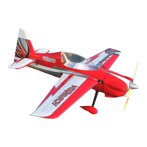
- Page 1 30cc MXS-Bach - Red - FUSION CONCEPT INSTRUCTION MANUAL...
- Page 2 30cc MXS-Bach, if not assembled and operated correctly, could possibly cause injury to yourself or spectators and damage property. It is highly recommend that before your maiden flight of your RedWing RC 30cc MXS-Bach you have an experienced, knowledgeable modeler do an extensive “pre-flight” inspection of your RedWing RC 30cc MXS-Bach for an added safety percussion.
-
Page 3: Contents Of Kit
Contents of Kit • All Our planes come with carbon fiber parts ( Spinners, Gear, Arms, Tubes). They are high quality with most features done for you already. • Pre glued cowling ring with blind nuts mounted to the fuselage •... - Page 4 • laser etched engine mounting template for the DLE30, DLE 35RA, or the PTE36 • Pre installed Pull Pull wire with ball links on rudder • Pre Cut Control horn slots • Floor and dashboard for cockpit pre installed...
-
Page 5: Main Landing Gear Installation
Main Landing Gear and Tail Wheel Main Landing Gear Installation • All parts for the Main landing gear • Install the landing gear in the pre drilled holes with the supplied “Phillips” head screws (with built in washer) and locking nuts. •... -
Page 6: Optional Steps
• Locate the blind nut and 2.5 Alan bolts. • Press the blind nut into the wheel pants as shown and install into the pre drilled holes on landing gear with Blue Loctite. Optional steps • use a Dremel tool with a cutting head to cut down the bolt that holds on the wheel pants for clearance of the wheel. -
Page 7: Tail Wheel Assembly
Tail Wheel Assembly All parts for the tail wheel • Locate the hard block on the bottom of the rudder and drill a 1/8 inch pilot hole and enlarge to 7/32 inch for the steering tube ◦ DO NOT glue at this time until tail wheel is installed and completed •... - Page 8 • Use the tail wheel screws to open the pre drilled holes in step above. ◦ Wick Thin CA into the holes • Once CA is dry attach the Tail Wheel mount and tail wheel to fuselage. Install the steering arm into the rudder steering tube and Epoxy the steering tube into place in the earlier drilled 7/32 inch hole.
-
Page 9: Main Wing Assembly
Main Wing Assembly All parts for the tail wheel • locate the pre cut control horn slots and the control horns with the pre installed ball link • use course, 60 grit sand paper or block and sand the lower unpainted portion of the control horn to ensure a good bond between the glue and surface of the control horn ( remove the shiny look) •... - Page 10 • prepare your servo buy centering it and adding your control horns along with a 6” Twisted Wire servo extension and a servo safety clip (sold separately at RedWing RC) • install the servo into the wing and drill holes in for the mounting screws and harden with thin CA.
- Page 11 • gather the Robart style hinges, masking tape, hole punch and choice of glue (again Gorilla Glue works very well here) ◦ Note: Highly recommended that you roughen the hinge with course 60 grit sand paper to allow for better adhesion with the glue and wood blocks inside wing •...
- Page 12 • Prepare the Turn buckle rods by installing the ball link and install on servo arm ◦ the turn buckle wrench from RedWing RC makes this and other field adjustments a breeze • Locate the SFG (Side Force Generators) location in the ends of the wings on the second rib.
-
Page 13: Rudder Installation
Rudder Installation All parts for the Rudder • Find and open the slots for the rudder control horn. Test fit the control horns on both sides and measure the correct length and trim the longer part on the non painted side of the control horn. - Page 14 • locate the re installed Pull Pull wire at the rear of the fuselage. Remove tape and thread the brass wire screws into the ball links attached to the control horn on both sides. • Just like in the wing installation drill and tap the servo screws and then wick thin CA into the holes to harden wood, then re-install servo •...
-
Page 15: Stabilizer Installation
Stabilizer Installation All parts needed • Find pre cut slots for the rudder control horn, Test fit the control horns on both sides. Prepare the control horns and slots as you did in the wing and Rudder installation. Once your comfortable with the way everything fits glue in the control horns, hinges and Elevators to the stabilizer fins •... -
Page 16: Engine Installation
• insert the carbon fiber stabilizer tube into the pre drilled hole • Locate the four (4) 5/64” screws and use Blue Loctite on the threads and attach the Stabilizers to the side of the fuselage • Connect the control horns to the centered servo using the provided ball link Engine Installation •... - Page 17 • Locate the laser etched motor mount standoff drill points. Use a smaller bit and increase size as you get to the correct diameter for the screws in your standoffs • Install the Standoff's with provided bolts. Install the bolt into a flat washer then insert into the firewall, then drop Blue Loctite on the threads and tighten standoff.
-
Page 18: Fuel Tank
• Locate the Engine access hatch and use self-ta screws to tightly secure to the engine mount mount box. Fuel Tank • Your RedWing RC MSX-Sbach comes with a pre plumbed fuel tank per-installed for you. If you chose to use this or an upgraded fuel tank the process is the same to installation... - Page 19 • Locate the carburetor supply nipple on the tank and run your line through the firewall to the carburetor • Run the vent and fuel supply line to the bottom and side of the fuselage place a vent line end on the vent line and attach to the fuselage. Use a fuel dot on the fuel fill line. Ensure that on the fuel fill line that you install a Gas safe fuel filter inline.
- Page 20 • If your not going to install a canister locate the canister bay cover and install with self-tapping screws to seal off the motor compartment from inside the fuselage • Canister • Remove the covering from the pre cut canister air exit opening and ensure the edge has been sealed.
-
Page 21: Center Of Gravity
• Locate the hole on the fuselage for the wing bolts and open them with a heated soldering iron. Use scrap cardboard of stiff paper to mark the location of the cowl mounting plate and transfer that to the cowl, drill a 1/8inc hole for the cowl screw to go though. Place the top cowl screws into the pre drilled hole and tighten. -
Page 22: Find The Center Of Gravity
Recommended CG: 5.25" to 5.5" from the LE at the root of the wing) Find the Center of Gravity Mean Aerodynamic Chord (MAC) One theory is that all aircraft should balance at a point defined as 25% of the Mean Aerodynamic Chord, with no consideration given to tail area or moment arm.
Need help?
Do you have a question about the 30cc MXS-Bach - Red - FUSION CONCEPT and is the answer not in the manual?
Questions and answers