Table of Contents
Advertisement
Quick Links
Installation and operation manual
Introduction
Thank you for purchasing this SynerTech product.
This Video door phone System is an easy-to-use and DIY installed video interphone system.
To obtain the best performance from this product, please read through this manual carefully. It
will guide you to operate a full set of HD-2192 and how to connect with out door camera and
the electronic door lock.
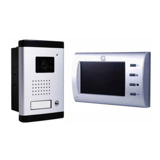
A. Name of parts, accessories and indicators for full set of VDP (HD-2192)
Indoor Unit (Fig.1)
1. Monitor screen
2. "TALK"button
3. "Monitor off"button
4. Integral microphone
5. "Door Open" button
6. "Monitor on " button
7. Wire terminal
8. DC socket
9. Wall mounting hole
10. Integral speaker
11. Label
12.Volume adjust hole;
Video door phone
(Model: HD-2192 )
Outdoor Unit (Fig.2)
a. Aluminum camera
case;
b. Integral speaker
c. Camera fixing screw
and cover
d. Integral microphone
e. "Call" button
Accessories (Included)
I. Phone set wall
mounting hole DIM
II. Camera set wall
mounting housing
(See fig.3)
III.
Communicating
cables (10 meter)
IV. Adaptor (See fig.5)
V.
Screws
1
Advertisement
Table of Contents

Related Manuals for SynerTech HD-2192

Summary of Contents for SynerTech HD-2192
- Page 1 This Video door phone System is an easy-to-use and DIY installed video interphone system. To obtain the best performance from this product, please read through this manual carefully. It will guide you to operate a full set of HD-2192 and how to connect with out door camera and the electronic door lock.
- Page 2 Indoor unit 15Volts DC 2 3 4 5 6 Fig.1 Outdoor unit Fig.2 Fig.3...
- Page 3 Preparation For Installation Recommended installation height (Fig.4) 30cm 30cm Fig. 4 The above diagram shows the position of the camera set and the phone unit. Recommended installation height is approximately 165cm* from the ground level for both unit.( In Asian countries, the recommended height should be 150cm.
- Page 4 Following the wiring diagram, connect the provided cable between the camera and the phone unit. Then connect the wires to the corresponding position between camera and main unit. i.e. Red wire =>1R; White wire => 2W; Brown Wire=>3B;Yellow wire=>4Y. If the Electronic Door Release is to be used, connect the “Door Open” key to the terminals as shown 5K1 &...
- Page 5 Locate and mark screwing positions on the wall. Drill the screws in but leave 5mm exposed. Hang the indoor unit on the screw and let it leveled against the wall. Ensuring the connecting cable runs tidily from indoor to outdoor unit. Installation precautions Before installing this product, please bear in mind of the following: DO NOT position the units where they will be subjected to extreme moisture,...
- Page 6 Monitor speaker volume adjustment The indoor unit speaker volume adjustment hole on the back of the monitor, The end user can use the small flat type or plus type screw driver adjust the semi-fixed resistor change the output sound like them desire level. If the output too loud will generate some feed back noise.
Need help?
Do you have a question about the HD-2192 and is the answer not in the manual?
Questions and answers